EP1333555A2 - Circuit and method for avoiding standby discharge of a battery fed signal evaluation circuit for a sensor - Google Patents
Circuit and method for avoiding standby discharge of a battery fed signal evaluation circuit for a sensor Download PDFInfo
- Publication number
- EP1333555A2 EP1333555A2 EP02027108A EP02027108A EP1333555A2 EP 1333555 A2 EP1333555 A2 EP 1333555A2 EP 02027108 A EP02027108 A EP 02027108A EP 02027108 A EP02027108 A EP 02027108A EP 1333555 A2 EP1333555 A2 EP 1333555A2
- Authority
- EP
- European Patent Office
- Prior art keywords
- circuit
- power supply
- charge
- signal evaluation
- sensor
- Prior art date
- Legal status (The legal status is an assumption and is not a legal conclusion. Google has not performed a legal analysis and makes no representation as to the accuracy of the status listed.)
- Withdrawn
Links
Images
Classifications
-
- A—HUMAN NECESSITIES
- A47—FURNITURE; DOMESTIC ARTICLES OR APPLIANCES; COFFEE MILLS; SPICE MILLS; SUCTION CLEANERS IN GENERAL
- A47L—DOMESTIC WASHING OR CLEANING; SUCTION CLEANERS IN GENERAL
- A47L9/00—Details or accessories of suction cleaners, e.g. mechanical means for controlling the suction or for effecting pulsating action; Storing devices specially adapted to suction cleaners or parts thereof; Carrying-vehicles specially adapted for suction cleaners
- A47L9/28—Installation of the electric equipment, e.g. adaptation or attachment to the suction cleaner; Controlling suction cleaners by electric means
- A47L9/2868—Arrangements for power supply of vacuum cleaners or the accessories thereof
- A47L9/2884—Details of arrangements of batteries or their installation
-
- A—HUMAN NECESSITIES
- A47—FURNITURE; DOMESTIC ARTICLES OR APPLIANCES; COFFEE MILLS; SPICE MILLS; SUCTION CLEANERS IN GENERAL
- A47L—DOMESTIC WASHING OR CLEANING; SUCTION CLEANERS IN GENERAL
- A47L9/00—Details or accessories of suction cleaners, e.g. mechanical means for controlling the suction or for effecting pulsating action; Storing devices specially adapted to suction cleaners or parts thereof; Carrying-vehicles specially adapted for suction cleaners
- A47L9/28—Installation of the electric equipment, e.g. adaptation or attachment to the suction cleaner; Controlling suction cleaners by electric means
- A47L9/2805—Parameters or conditions being sensed
- A47L9/281—Parameters or conditions being sensed the amount or condition of incoming dirt or dust
-
- H—ELECTRICITY
- H01—ELECTRIC ELEMENTS
- H01M—PROCESSES OR MEANS, e.g. BATTERIES, FOR THE DIRECT CONVERSION OF CHEMICAL ENERGY INTO ELECTRICAL ENERGY
- H01M10/00—Secondary cells; Manufacture thereof
- H01M10/42—Methods or arrangements for servicing or maintenance of secondary cells or secondary half-cells
- H01M10/425—Structural combination with electronic components, e.g. electronic circuits integrated to the outside of the casing
-
- H—ELECTRICITY
- H01—ELECTRIC ELEMENTS
- H01M—PROCESSES OR MEANS, e.g. BATTERIES, FOR THE DIRECT CONVERSION OF CHEMICAL ENERGY INTO ELECTRICAL ENERGY
- H01M50/00—Constructional details or processes of manufacture of the non-active parts of electrochemical cells other than fuel cells, e.g. hybrid cells
- H01M50/50—Current conducting connections for cells or batteries
- H01M50/572—Means for preventing undesired use or discharge
- H01M50/574—Devices or arrangements for the interruption of current
-
- H—ELECTRICITY
- H02—GENERATION; CONVERSION OR DISTRIBUTION OF ELECTRIC POWER
- H02J—CIRCUIT ARRANGEMENTS OR SYSTEMS FOR SUPPLYING OR DISTRIBUTING ELECTRIC POWER; SYSTEMS FOR STORING ELECTRIC ENERGY
- H02J9/00—Circuit arrangements for emergency or stand-by power supply, e.g. for emergency lighting
- H02J9/005—Circuit arrangements for emergency or stand-by power supply, e.g. for emergency lighting using a power saving mode
-
- Y—GENERAL TAGGING OF NEW TECHNOLOGICAL DEVELOPMENTS; GENERAL TAGGING OF CROSS-SECTIONAL TECHNOLOGIES SPANNING OVER SEVERAL SECTIONS OF THE IPC; TECHNICAL SUBJECTS COVERED BY FORMER USPC CROSS-REFERENCE ART COLLECTIONS [XRACs] AND DIGESTS
- Y02—TECHNOLOGIES OR APPLICATIONS FOR MITIGATION OR ADAPTATION AGAINST CLIMATE CHANGE
- Y02E—REDUCTION OF GREENHOUSE GAS [GHG] EMISSIONS, RELATED TO ENERGY GENERATION, TRANSMISSION OR DISTRIBUTION
- Y02E60/00—Enabling technologies; Technologies with a potential or indirect contribution to GHG emissions mitigation
- Y02E60/10—Energy storage using batteries
Definitions
- the invention relates to a method for avoiding the standby discharge of a battery-powered device Signal evaluation circuit for the charge signals of a sensor, in particular the Dust sensor of a vacuum cleaner.
- the invention further relates to a circuit arrangement for Execution of the procedure.
- EP 0 759 157 A1 uses a method for the detection of dust particles a signal evaluation circuit for the dust sensor of a vacuum cleaner known the circuit and sensor are powered by a battery.
- the signal evaluation circuit which the charge signals of the arranged in the floor nozzle of the vacuum cleaner receives piezoceramic dust sensor, consists essentially of a Signal amplifier with downstream signal filters, threshold detectors and other electronic Components that are constantly in operation of the vacuum cleaner with the battery voltage are acted upon.
- the known circuit arrangement thus takes from the battery a considerable quiescent current (of the order of magnitude) during the suction pauses (standby mode) of approx. 10 mA), which leads to a rapid discharge of the battery over time.
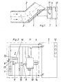
- Fig. 1 shows a piezoelectric dust sensor (1), in particular in a flow path in the angled connecting piece (2) of the floor nozzle of a vacuum cleaner, not shown is arranged.
- the dust particles moving through the floor nozzle (3) meet in the area of the pipe bend of the connection piece (2) on the one attached there piezoelectric dust sensor (1).
- the kinetic energy or the change in momentum of the The sensor converts dust particles (3) into a corresponding electrical signal.
- This so-called Charge signal (L) is fed via a line branch (4) to a signal evaluation circuit (5), whose operating voltage (battery voltage U of a battery 6) via an upstream Power supply circuit (7) is applied.
- the power supply circuit (7) with the dust sensor (1) is constantly connected to the battery, sh. also Fig. 2.
- Fig. 2 shows a simple block diagram of the signal evaluation circuit (5), which after Formation and function of a measuring circuit shown in EP 0 759 157 A1 corresponds.
- the known circuit is also battery-powered.
- Power supply circuit (7) with the dust sensor (1) for the signal evaluation circuit (5) is designed as a power switch and switches the signal evaluation circuit (5) in the case of dust particle sensing on the battery voltage (U) and in the de-energized Standby mode if no dust particles (3) are sensed.
- the power supply is switched off causes.
- the power supply is switched on and off from the amplitude values the charge signals (L) of the dust sensor (1) controlled depending on what threshold values or Sensitivity settings of the following amplifiers can be adjusted.
- Switching on and off the battery voltage (U) to the signal evaluation circuit (5) is a function of time or occurrence of the successive charge signals (L) of the piezoelectric dust sensor (1) dependent.
- These charge or trigger signals (L) are both the signal evaluation circuit (5), and separately via a feed line (17) that shown in Fig. 2 Power supply circuit (7) supplied.
- the dust sensor (1) is constantly on battery voltage (U) arranged power supply circuit (7) arranged, the power supply circuit (7) a charge signal amplifier (8) with a downstream comparator (9) for the preparation of the dust sensor via the line branch (4) or the feed line (17) (1) coming charge signals (L) includes.
- the processed charge signals (L) are fed to a monostable multivibrator (10), the output of which is the battery voltage (U) on the signal evaluation circuit (5) applying transistor (11) on and off.
- the charge signals (L) coming via the line branch (4) are also the Signal evaluation circuit (5) supplied, which ultimately via an associated display (12) informs the operator of the suction result when vacuuming.
- the operator display (12) can provide information on the respective dust particle level acoustically or optically.
- the charge signal amplifier (8) detects depending on the sensitivity - adjustable by a transverse capacitance (13) and a transverse resistor (16) - the operating noise of the vacuum cleaner and impinging dust particles (3).
- the comparator (9) forms the noisy output signal of the Charge signal amplifier (8) in rectangular signal blocks, whereupon this the monostable multivibrator (10) trigger.
- the monostable multivibrator (10) switches for via its resistor / capacitor combination (14) set time (e.g. about 1 second) the transistor (11), whereupon the battery voltage (U) is switched through to the signal evaluation circuit (5) becomes. As long as the dust sensor (1) delivers signals, the flip-flop (10) is always on triggered so that the operating time starts all over again.
- the voltage to the signal evaluation circuit (5) is preferably within about 1 second interrupted.
- the reset time of the monostable multivibrator (10) of the power supply circuit (7) can be changed by changing the resistance / capacitor values from (14) can be varied.
- Via a voltage divider (15) connected to the battery voltage (U) is the sensitivity (switching threshold) of the amplified charge signals (L) (or trigger signals) adjustable.
- the charge signal amplifier (8) leading supply line (17) branching off from the line branch (4) also a decoupling switch (18) can be placed by the electronics of the vacuum cleaner is operated.
- This switch (18) could be a transistor or a relay contact. In standby mode the switch (18) is closed. If dust signals are received, the Comparator (9) the monoflop and thus the display (12) for the first time for approx. 1 to 2 seconds switched on.
- the switch (18) opens and the sensor signals (L) are decoupled from the charge amplifier (8). After the expiration of the "Single phase” switches the monoflop (10) the battery-supplied signal evaluation circuit (5) again out. The switch (18) closes again and the triggering starts again.
- the switch in the line branch (4) or both Lines (4, 17) to be provided with switches (18).
- a quiescent current consumption determined in the experiment with the circuit arrangement according to the invention gave a current value of approx. 70 microamps at 6 volt battery voltage.
- the charge signal amplifier of the power supply circuit was advantageous as a multiple operational amplifier (e.g. dual amplifier).
- four 1.5 V Mignon cells with a capacity of approx. 2 Ah and an effective suction time with the vacuum cleaner of 50 hours / year, with an average current consumption of 30 mA depending on the number the indicator lamps of the switched-on display device of the signal evaluation circuit battery life is around 1.5 years.
- the low power consumption of the power supply circuit (7) of about 70 microamps results from the use of low or micro power semiconductors in the circuit.
- the invention enables the implementation of inexpensive electronics which save space and also possibly location-independent in a vacuum cleaner or its floor nozzle, e.g. B. also in Handle to be installed. Due to the "power switch function" of the Power supply circuit (7) for the signal evaluation circuit (5) is a long battery life possible in standby mode. Instead of a piezoelectric dust sensor (1) could also be a photoelectric or optoelectronic dust sensor if the circuit is adapted be used. In addition, the invention can of course also be applied other battery operated electronic circuits with sensors that apply signals generated that can be used for triggering.
Abstract
Description
Die Erfindung betrifft ein Verfahren zur Vermeidung der Standby-Entladung einer batterieversorgten Signal-Auswerteschaltung für die Ladungssignale eines Sensors, insbesondere des Staubsensors eines Staubsaugers. Ferner betrifft die Erfindung eine Schaltungsanordnung zur Durchführung des Verfahrens.The invention relates to a method for avoiding the standby discharge of a battery-powered device Signal evaluation circuit for the charge signals of a sensor, in particular the Dust sensor of a vacuum cleaner. The invention further relates to a circuit arrangement for Execution of the procedure.
Aus der EP 0 759 157 A1 ist ein Verfahren zum Nachweis von Staubpartikeln unter Verwendung einer Signal-Auswerteschaltung für den Staubsensor eines Staubsaugers bekannt, bei dem Schaltung und Sensor von einer Batterie energieseitig versorgt werden. Die Signal-Auswerteschaltung, welche die Ladungssignale des in der Bodendüse des Staubsaugers angeordneten piezokeramischen Staubsensors empfängt, besteht im wesentlichen aus einem Signalverstärker mit nachgeschalteten Signalfiltern, Schwellwertdetektoren und anderen elektronischen Bauelementen, welche im Ruhebetrieb des Staubsaugers ständig mit der Batteriespannung beaufschlagt sind. Die bekannte Schaltungsanordnung entnimmt der Batterie somit in den Saugpausen (Standby-Betrieb) einen erheblichen Ruhestrom (in der Größenordnung von ca. 10 mA), der im Verlauf der Zeit zu einer schnellen Entladung der Batterie führt.EP 0 759 157 A1 uses a method for the detection of dust particles a signal evaluation circuit for the dust sensor of a vacuum cleaner known the circuit and sensor are powered by a battery. The signal evaluation circuit, which the charge signals of the arranged in the floor nozzle of the vacuum cleaner receives piezoceramic dust sensor, consists essentially of a Signal amplifier with downstream signal filters, threshold detectors and other electronic Components that are constantly in operation of the vacuum cleaner with the battery voltage are acted upon. The known circuit arrangement thus takes from the battery a considerable quiescent current (of the order of magnitude) during the suction pauses (standby mode) of approx. 10 mA), which leads to a rapid discharge of the battery over time.
Ferner ist es bei einer Sensoreinrichtung für einen Staubsauger bekannt, die Ruhestromentladung mit Hilfe eines mechanischen Unterdruckschalters zu verhindern. Immer dann, wenn der Staubsauger arbeitet, wird der Unterdruckschalter betätigt und legt die Sensoreinheit an die Betriebsspannung. Diese Lösung ist insofern nachteilig, da hier der Unterdruckschalter in der Funktion als Ein/Ausschalter für die Stromversorgung einem zunehmenden mechanischen Verschleiß unterliegt und zudem noch einen eigenen Bauraum außerhalb der Elektronik benötigt. Der Erfindung liegt die Aufgabe zugrunde, hier Abhilfe zu schaffen.Furthermore, it is known in a sensor device for a vacuum cleaner, the quiescent current discharge with the help of a mechanical vacuum switch. Whenever the Vacuum cleaner works, the vacuum switch is actuated and places the sensor unit on the Operating voltage. This solution is disadvantageous in that the vacuum switch in the Function as an on / off switch for the power supply increasing mechanical wear subject and also requires its own installation space outside the electronics. The object of the invention is to remedy this.
Erfindungsgemäß werden die vorgenannten Probleme mit dem im Patentanspruch 1 angegebenen
Verfahrensschritt gelöst. Vorteilhafte Weiterbildungen der Erfindung ergeben sich aus
den nachfolgenden Unteransprüchen. Eine entsprechende elektronische Schaltungsanordnung
zur Durchführung des Verfahrens ist durch den Patentanspruch 5 gekennzeichnet. Die sich
diesem Patentbegehren anschließenden Unteransprüche ergeben vorteilhafte Ausgestaltungen
der Schaltungsanordnung.According to the invention, the aforementioned problems with that specified in
Dadurch, dass Ladungssignale, wenn diese auftreten, ein Anschalten der Stromversorgung der Signal-Auswerteschaltung und ein Ausbleiben der Ladungssignale ein Abschalten der Stromversorgung veranlasst, kann auf jegliche elektromechanische Schalter, insbesondere auf verschleißanfällige Unterdruckschalter verzichtet werden. Hierdurch ist es vorteilhaft möglich, eine preiswerte Elektronik raumsparend und ggf. nicht ortsgebunden zu realisieren, welche aufgrund ihrer erfindungsgemäßen "Netzschalterfunktion" für die Signal-Auswerteschaltung eine lange Batterielebensdauer im Standby-Betrieb ermöglicht.The fact that charge signals, when they occur, turn on the power supply to the Signal evaluation circuit and a failure of the charge signals to switch off the power supply caused, can on any electromechanical switch, especially wear-prone Vacuum switch can be dispensed with. This advantageously makes it possible To implement inexpensive electronics space-saving and possibly not localized, which due to their "power switch function" according to the invention for the signal evaluation circuit a long Battery life in standby mode enabled.
Ein Ausführungsbeispiel der Erfindung ist in den Zeichnungen rein schematisch dargestellt und wird nachfolgend näher beschrieben. Es zeigt
Figur 1- eine Anordnung eines piezoelektrischen Staubsensors im Strömungsweg einer Bodendüse eines Staubsaugers, wobei dem Staubsensor eine Signal-Auswerteschaltung mit zugeordnetem Stromversorgungs-Schaltkreis nachgeschaltet ist,
- Figur 2
- den Stromversorgungs-Schaltkreis mit dem Staubsensor im Detail sowie die nachgeschaltete Signal-Auswerteschaltung im vereinfachten Blockschaltbild.
Figur 3- die elektrische Schaltung nach Fig. 2 in vereinfachter Darstellung mit einem zusätzlichen Entkopplungs-Schalter.
- Figure 1
- an arrangement of a piezoelectric dust sensor in the flow path of a floor nozzle of a vacuum cleaner, the dust sensor being followed by a signal evaluation circuit with an associated power supply circuit,
- Figure 2
- the power supply circuit with the dust sensor in detail and the downstream signal evaluation circuit in the simplified block diagram.
- Figure 3
- the electrical circuit of FIG. 2 in a simplified representation with an additional decoupling switch.
Die Fig. 1 zeigt einen piezoelektrischen Staubsensor (1), der in einem Strömungsweg, insbesondere im abgewinkelten Anschlußstutzen (2) der Bodendüse eines nicht dargestellten Staubsaugers angeordnet ist. Der von der Bodendüse im Saugbetrieb aufgenommene Staub wird durch die Saugleistung des Staubsaugers in einer durch einen Pfeil bestimmten Strömungsrichtung durch den Anschlußstutzen (2) bewegt. Die durch die Bodendüse bewegten Staubpartikel (3) treffen im Bereich der Rohrkrümmung des Anschlußstutzens (2) auf den dort angebrachten piezoelektrischen Staubsensor (1). Die Bewegungsenergie bzw. die Impulsänderung der Staubpartikel (3) wandelt der Sensor in ein entsprechendes elektrisches Signal um. Dieses sog. Ladungssignal (L) wird über einen Leitungszweig (4) einer Signal-Auswerteschaltung (5) zugeführt, deren Betriebsspannung (Batteriespannung U einer Batterie 6) über einen vorgeschalteten Stromversorgungs-Schaltkreis (7) angelegt wird. Der Stromversorgungs-Schaltkreis (7) mit dem Staubsensor (1) ist ständig mit der Batterie verbunden, sh. auch Fig. 2.Fig. 1 shows a piezoelectric dust sensor (1), in particular in a flow path in the angled connecting piece (2) of the floor nozzle of a vacuum cleaner, not shown is arranged. The dust picked up by the floor nozzle in suction mode by the suction power of the vacuum cleaner in a flow direction determined by an arrow moved through the connecting piece (2). The dust particles moving through the floor nozzle (3) meet in the area of the pipe bend of the connection piece (2) on the one attached there piezoelectric dust sensor (1). The kinetic energy or the change in momentum of the The sensor converts dust particles (3) into a corresponding electrical signal. This so-called Charge signal (L) is fed via a line branch (4) to a signal evaluation circuit (5), whose operating voltage (battery voltage U of a battery 6) via an upstream Power supply circuit (7) is applied. The power supply circuit (7) with the dust sensor (1) is constantly connected to the battery, sh. also Fig. 2.
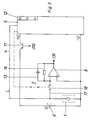
Die Fig. 2 zeigt im einfachen Blockschaltbild die Signal-Auswerteschaltung (5), welche nach Ausbildung und Funktion einer in der EP 0 759 157 A1 gezeigten Mess-Schaltung entspricht. Auch die bekannte Schaltung ist batteriegespeist. Der in Fig. 2 jedoch im Detail gezeigte Stromversorgungs-Schaltkreis (7) mit dem Staubsensor (1) für die Signal-Auswerteschaltung (5) ist in Funktion eines Netzschalters ausgebildet und schaltet die Signal-Auswerteschaltung (5) bei einer Staubpartikelsensierung an die Batteriespannung (U) und in den spannungslosen Standby-Betrieb, wenn keine Staubpartikel (3) sensiert werden. Fig. 2 shows a simple block diagram of the signal evaluation circuit (5), which after Formation and function of a measuring circuit shown in EP 0 759 157 A1 corresponds. The known circuit is also battery-powered. The one shown in detail in FIG. 2 Power supply circuit (7) with the dust sensor (1) for the signal evaluation circuit (5) is designed as a power switch and switches the signal evaluation circuit (5) in the case of dust particle sensing on the battery voltage (U) and in the de-energized Standby mode if no dust particles (3) are sensed.
Erfindungsgemäß wird eine Standby-Entladung der batterieversorgten Signal-Auswerteschaltung (5) also dadurch vermieden, dass auftretende Ladungssignale (L) des Sensors (1) zum Anschalten der Stromversorgung der Signal-Auswerteschaltung (5) herangezogen werden, und dass ein Ausbleiben der Ladungssignale (L) ein Abschalten der Stromversorgung veranlasst. Dabei ist das An- und Abschalten der Stromversorgung von den Amplitudenwerten der Ladungssignale (L) des Staubsensors (1) abhängig gesteuert, wozu Schwellwerte oder Empfindlichkeitseinstellungen der nachfolgenden Verstärker einstellbar sind. Das An- und Abschalten der Batteriespannung (U) an die Signal-Auswerteschaltung (5) ist vom zeitlichen Verlauf bzw. Auftreten der aufeinanderfolgenden Ladungssignale (L) des piezoelektrischen Staubsensors (1) abhängig. Diese Ladungs- oder Triggersignale (L) werden sowohl der Signal-Auswerteschaltung (5), als auch separat über eine Zuleitung (17) dem in Fig. 2 gezeigten Stromversorgungs-Schaltkreis (7) zugeführt.According to the invention, there is a standby discharge of the battery-supplied signal evaluation circuit (5) thus avoided by the fact that charge signals (L) from the sensor occur (1) used to switch on the power supply of the signal evaluation circuit (5) and that there is no charge signal (L), the power supply is switched off causes. The power supply is switched on and off from the amplitude values the charge signals (L) of the dust sensor (1) controlled depending on what threshold values or Sensitivity settings of the following amplifiers can be adjusted. Switching on and off the battery voltage (U) to the signal evaluation circuit (5) is a function of time or occurrence of the successive charge signals (L) of the piezoelectric dust sensor (1) dependent. These charge or trigger signals (L) are both the signal evaluation circuit (5), and separately via a feed line (17) that shown in Fig. 2 Power supply circuit (7) supplied.
Nach der Schaltungsanordnung gemäß Fig. 2 ist der Staubsensor (1) in dem ständig an Batteriespannung (U) gelegten Stromversorgungs-Schaltkreis (7) angeordnet, wobei der Stromversorgungs-Schaltkreis (7) einen Ladungssignalverstärker (8) mit einem nachgeschalteten Komparator (9) zur Aufbereitung der über den Leitungszweig (4) bzw. die Zuleitung (17) vom Staubsensor (1) kommenden Ladungssignale (L) beinhaltet. Die aufbereiteten Ladungssignale (L) werden einer monostabilen Kippschaltung (10) zugeführt, deren Ausgang einen die Batteriespannung (U) an die Signal-Auswerteschaltung (5) anlegenden Transistor (11) ein- und ausschaltet. Die über den Leitungszweig (4) kommenden Ladungssignale (L) werden ebenfalls der Signal-Auswerteschaltung (5) zugeführt, welche letztlich über eine zugeordnete Anzeige (12) den Bediener beim Staubsaugen über das Saugergebnis informiert. Die Bedieneranzeige (12) kann akustisch oder optisch über den jeweiligen Staubpartikelgrad informieren.According to the circuit arrangement according to FIG. 2, the dust sensor (1) is constantly on battery voltage (U) arranged power supply circuit (7) arranged, the power supply circuit (7) a charge signal amplifier (8) with a downstream comparator (9) for the preparation of the dust sensor via the line branch (4) or the feed line (17) (1) coming charge signals (L) includes. The processed charge signals (L) are fed to a monostable multivibrator (10), the output of which is the battery voltage (U) on the signal evaluation circuit (5) applying transistor (11) on and off. The charge signals (L) coming via the line branch (4) are also the Signal evaluation circuit (5) supplied, which ultimately via an associated display (12) informs the operator of the suction result when vacuuming. The operator display (12) can provide information on the respective dust particle level acoustically or optically.
Der Ladungssignalverstärker (8) erfasst je nach Empfindlichkeit - einstellbar durch eine Querkapazität (13) und einen Querwiderstand (16) - das Betriebsgeräusch des Staubsaugers und auftreffende Staubpartikel (3). Der Komparator (9) formt das verrauschte Ausgangssignal des Ladungssignalverstärkers (8) in Rechtecksignalblöcke um, worauf diese die monostabile Kippschaltung (10) triggern. Die monostabile Kippschaltung (10) schaltet für die über ihre Widerstands/Kondensator-Kombination (14) festgelegte Zeit (z. B. ca. 1 Sekunde) den Transistor (11) ein, worauf die Batteriespannung (U) an die Signal-Auswerteschaltung (5) durchgeschaltet wird. Solange der Staubsensor (1) Signale liefert, wird die Kippschaltung (10) immer wieder getriggert, so dass die Betriebszeit permanent neu beginnt. Treffen keine Signale mehr ein, so wird die Spannung zur Signal-Auswerteschaltung (5) vorzugsweise innerhalb von ca. 1 Sekunde unterbrochen. Die Rückstellzeit der monostabilen Kippschaltung (10) des Stromversorgungs-Schaltkreises (7) kann durch eine Änderung der Widerstands/Kondensatorwerte von (14) variiert werden. Über einen an der Batteriespannung (U) liegenden Spannungsteiler (15) ist die Empfindlichkeit (Schaltschwelle) der verstärkten Ladungssignale (L) (oder Triggersignale) einstellbar.The charge signal amplifier (8) detects depending on the sensitivity - adjustable by a transverse capacitance (13) and a transverse resistor (16) - the operating noise of the vacuum cleaner and impinging dust particles (3). The comparator (9) forms the noisy output signal of the Charge signal amplifier (8) in rectangular signal blocks, whereupon this the monostable multivibrator (10) trigger. The monostable multivibrator (10) switches for via its resistor / capacitor combination (14) set time (e.g. about 1 second) the transistor (11), whereupon the battery voltage (U) is switched through to the signal evaluation circuit (5) becomes. As long as the dust sensor (1) delivers signals, the flip-flop (10) is always on triggered so that the operating time starts all over again. If there are no more signals, so the voltage to the signal evaluation circuit (5) is preferably within about 1 second interrupted. The reset time of the monostable multivibrator (10) of the power supply circuit (7) can be changed by changing the resistance / capacitor values from (14) can be varied. Via a voltage divider (15) connected to the battery voltage (U) is the sensitivity (switching threshold) of the amplified charge signals (L) (or trigger signals) adjustable.
Gemäß einer vorteilhaften Weiterbildung der Erfindung kann gemäß Fig. 3 in die zum Ladungssignalverstärker (8) führende und vom Leitungszweig (4) abzweigende Zuleitung (17) auch ein Entkopplungs-Schalter (18) gelegt werden, der von der Elektronik des Staubsaugers betätigt wird. Dieser Schalter (18) könnte ein Transistor oder ein Relaiskontakt sein. Im Standby-Betrieb ist der Schalter (18) geschlossen. Werden Staubsignale empfangen, wird über den Komparator (9) das Monoflop und damit die Anzeige (12) erstmalig für ca. 1 bis 2 Sekunden eingeschaltet. In der "Einphase" der monostabilen Kippschaltung (10) öffnet der Schalter (18) und die Sensorsignale (L) werden vom Ladungsverstärker (8) abgekoppelt. Nach Ablauf der "Einphase" schaltet das Monoflop (10) die batterieversorgte Signal-Auswerteschaltung (5) wieder aus. Der Schalter (18) schließt wieder und die Triggerung beginnt erneut. Durch diese Variante ergeben sich vorteilhafte Merkmale in der Entkopplung von Ladungsverstärker und Elektronik. Auch besteht die Möglichkeit, den Schalter in den Leitungszweig (4) zu legen oder beide Leitungen (4, 17) mit Schaltern (18) zu versehen.According to an advantageous development of the invention, according to FIG. 3, the charge signal amplifier (8) leading supply line (17) branching off from the line branch (4) also a decoupling switch (18) can be placed by the electronics of the vacuum cleaner is operated. This switch (18) could be a transistor or a relay contact. In standby mode the switch (18) is closed. If dust signals are received, the Comparator (9) the monoflop and thus the display (12) for the first time for approx. 1 to 2 seconds switched on. In the "single phase" of the monostable multivibrator (10), the switch (18) opens and the sensor signals (L) are decoupled from the charge amplifier (8). After the expiration of the "Single phase" switches the monoflop (10) the battery-supplied signal evaluation circuit (5) again out. The switch (18) closes again and the triggering starts again. Through this variant there are advantageous features in the decoupling of charge amplifier and electronics. It is also possible to put the switch in the line branch (4) or both Lines (4, 17) to be provided with switches (18).
Eine im Versuch mit der erfindungsgemäßen Schaltungsanordnung ermittelte Ruhestromaufnahme ergab bei 6 Volt Batteriespannung einen Stromwert von ca. 70 Mikroampere. Dabei wurde der Ladungssignalverstärker des Stromversorgungs-Schaltkreises vorteilhaft als Mehrfachoperationsverstärker (z. B. Zweifachverstärker) ausgebildet. Bei Verwendung von vier 1,5 V Mignonzellen mit einer Kapazität von ca. 2 Ah und einer effektiven Saugzeit mit dem Staubsauger von 50 Std./Jahr, wobei eine Stromaufnahme von durchschnittlich 30 mA je nach Anzahl der Anzeigelampen der eingeschalteten Anzeigeeinrichtung der Signal-Auswerteschaltung angenommen wird, ergibt sich eine Batterielebensdauer von etwa 1,5 Jahren. Die geringe Stromaufnahme des Stromversorgungs-Schaltkreises (7) von etwa 70 Mikroampere ergibt sich durch die Verwendung von Low- oder Micropower-Halbleitern in der Schaltung.A quiescent current consumption determined in the experiment with the circuit arrangement according to the invention gave a current value of approx. 70 microamps at 6 volt battery voltage. there the charge signal amplifier of the power supply circuit was advantageous as a multiple operational amplifier (e.g. dual amplifier). When using four 1.5 V Mignon cells with a capacity of approx. 2 Ah and an effective suction time with the vacuum cleaner of 50 hours / year, with an average current consumption of 30 mA depending on the number the indicator lamps of the switched-on display device of the signal evaluation circuit battery life is around 1.5 years. The low power consumption of the power supply circuit (7) of about 70 microamps results from the use of low or micro power semiconductors in the circuit.
Die Erfindung ermöglicht die Realisierung einer preiswerten Elektronik, welche raumsparend und auch ggf. ortsunabhängig in einem Staubsauger oder dessen Bodendüse, z. B. auch im Handgriff, zu installieren ist. Aufgrund der erfindungsgemäßen "Netzschalterfunktion" des Stromversorgungs-Schaltkreises (7) für die Signal-Auswerteschaltung (5) ist eine lange Batterielebensdauer im Standby-Betrieb möglich. Statt eines piezoelektrischen Staubsensors (1) könnte bei angepasster Schaltung auch ein photoelektrischer oder optoelektronischer Staubsensor verwendet werden. Darüber hinaus lässt sich die Erfindung selbstverständlich auch auf andere batteriebetriebene elektronische Schaltungen mit Sensoren anwenden, mit denen Signale erzeugt werden, die zum Triggern verwendet werden können.The invention enables the implementation of inexpensive electronics which save space and also possibly location-independent in a vacuum cleaner or its floor nozzle, e.g. B. also in Handle to be installed. Due to the "power switch function" of the Power supply circuit (7) for the signal evaluation circuit (5) is a long battery life possible in standby mode. Instead of a piezoelectric dust sensor (1) could also be a photoelectric or optoelectronic dust sensor if the circuit is adapted be used. In addition, the invention can of course also be applied other battery operated electronic circuits with sensors that apply signals generated that can be used for triggering.
Claims (10)
dadurch gekennzeichnet, dass auftretende Ladungssignale (L) des Sensors (1) zum Anschalten der Stromversorgung der Signal-Auswerteschaltung (5) herangezogen werden, und dass ein Ausbleiben der Ladungssignale (L) ein Abschalten der Stromversorgung veranlasst.Method for avoiding the standby discharge of a battery-supplied signal evaluation circuit for the charge signals of a sensor, in particular the dust sensor of a vacuum cleaner,
characterized in that occurring charge signals (L) of the sensor (1) are used to switch on the power supply of the signal evaluation circuit (5), and in that the absence of the charge signals (L) causes the power supply to be switched off.
dadurch gekennzeichnet, dass das An- und Abschalten der Batteriespannung (U) von den Amplitudenwerten der Ladungssignale (L) des Staubsensors (1) abhängig gesteuert ist.Method according to claim 1,
characterized in that the switching on and off of the battery voltage (U) is controlled as a function of the amplitude values of the charge signals (L) of the dust sensor (1).
dadurch gekennzeichnet, dass die Ladungssignale (L) in ihrer Empfindlichkeit einstellbar sind.Method according to claim 1 or 2,
characterized in that the charge signals (L) are adjustable in their sensitivity.
dadurch gekennzeichnet, dass das An- und Abschalten der Batteriespannung (U) vom zeitlichen Verlauf aufeinanderfolgender Ladungssignale (L) abhängig gesteuert ist.Method according to one or more of claims 1 to 3,
characterized in that the switching on and off of the battery voltage (U) is controlled as a function of the time course of successive charge signals (L).
dadurch gekennzeichnet, dass der Stromversorgungs-Schaltkreis (7) mit dem Staubsensor (1) in Funktion eines Netzschalters (Transistor 11) für die Signal-Auswerteschaltung (5) ausgebildet ist.Circuit arrangement for carrying out the method according to claim 1, wherein the dust sensor is arranged in a power supply circuit permanently connected to the supply voltage of a battery,
characterized in that the power supply circuit (7) with the dust sensor (1) is designed as a power switch (transistor 11) for the signal evaluation circuit (5).
dadurch gekennzeichnet, dass der von der Batterie (6) ständig gespeiste Stromversorgungs-Schaltkreis (7) einen Ladungssignalverstärker (8) mit einem nachgeschalteten Komparator (9) zur Aufbereitung der Ladungssignale (L) vom Staubsensor (1) beinhaltet, wobei die aufbereiteten Ladungssignale (L) einer monostabilen Kippschaltung (10) zugeführt sind, deren Ausgang einen die Batteriespannung (U) an die Signal-Auswerteschaltung (5) anlegenden Transistor (11) ein- und ausschaltet. Circuit arrangement according to claim 5,
characterized in that the power supply circuit (7) continuously fed by the battery (6) contains a charge signal amplifier (8) with a downstream comparator (9) for processing the charge signals (L) from the dust sensor (1), the processed charge signals ( L) are fed to a monostable multivibrator (10), the output of which switches a transistor (11) which applies the battery voltage (U) to the signal evaluation circuit (5) on and off.
dadurch gekennzeichnet, dass die Ladungssignale (L) des Staubsensors (1) im Stromversorgungs-Schaltkreis (7) durch einen Spannungsteiler (15) und/oder durch eine Widerstands/Kondensator-Kombination (Querkapazität 13, Querwiderstand 16) in ihrer Empfindlichkeit einstellbar sind.Circuit arrangement according to claim 5 and 6,
characterized in that the charge signals (L) of the dust sensor (1) in the power supply circuit (7) can be adjusted in their sensitivity by a voltage divider (15) and / or by a resistor / capacitor combination (transverse capacitance 13, transverse resistor 16).
dadurch gekennzeichnet, dass die Rückstellzeit der monostabilen Kippschaltung (10) des Stromversorgungs-Schaltkreises (7) variierbar ist.Circuit arrangement according to one of claims 5 to 7,
characterized in that the reset time of the monostable multivibrator (10) of the power supply circuit (7) can be varied.
dadurch gekennzeichnet, dass in einer Zuleitung (17) zum Ladungsverstärker (8) und/oder im Leitungszweig (4) ein Schalter (18) zur Entkopplung des Ladungssignalverstärkers (8) und/oder der Signal-Auswerteschaltung (5) angeordnet ist.Circuit arrangement according to one of claims 5 to 8,
characterized in that a switch (18) for decoupling the charge signal amplifier (8) and / or the signal evaluation circuit (5) is arranged in a feed line (17) to the charge amplifier (8) and / or in the line branch (4).
dadurch gekennzeichnet, dass der Ladungssignalverstärker (8) des Stromversorgungs-Schaltkreis (7) vorzugsweise als Mehrfachoperationsverstärker ausgebildet ist.Circuit arrangement according to one of claims 5 to 9,
characterized in that the charge signal amplifier (8) of the power supply circuit (7) is preferably designed as a multiple operational amplifier.
Applications Claiming Priority (2)
| Application Number | Priority Date | Filing Date | Title |
|---|---|---|---|
| DE10204070A DE10204070A1 (en) | 2002-02-01 | 2002-02-01 | Method and circuit arrangement for avoiding the standby discharge of a battery-supplied signal evaluation circuit for a sensor |
| DE10204070 | 2002-02-01 |
Publications (2)
| Publication Number | Publication Date |
|---|---|
| EP1333555A2 true EP1333555A2 (en) | 2003-08-06 |
| EP1333555A3 EP1333555A3 (en) | 2006-07-12 |
Family
ID=7713524
Family Applications (1)
| Application Number | Title | Priority Date | Filing Date |
|---|---|---|---|
| EP02027108A Withdrawn EP1333555A3 (en) | 2002-02-01 | 2002-12-04 | Circuit and method for avoiding standby discharge of a battery fed signal evaluation circuit for a sensor |
Country Status (3)
| Country | Link |
|---|---|
| US (1) | US6801015B2 (en) |
| EP (1) | EP1333555A3 (en) |
| DE (1) | DE10204070A1 (en) |
Cited By (1)
| Publication number | Priority date | Publication date | Assignee | Title |
|---|---|---|---|---|
| EP3482667A1 (en) * | 2017-11-13 | 2019-05-15 | LG Electronics Inc. | Dust sensor module and operating method thereof |
Families Citing this family (5)
| Publication number | Priority date | Publication date | Assignee | Title |
|---|---|---|---|---|
| US6956348B2 (en) * | 2004-01-28 | 2005-10-18 | Irobot Corporation | Debris sensor for cleaning apparatus |
| US20020106308A1 (en) * | 2001-02-02 | 2002-08-08 | Zweifel Ronald A. | Microdrop dispensing apparatus |
| DE102004007677B4 (en) * | 2004-02-16 | 2011-11-17 | Miele & Cie. Kg | Suction nozzle for a vacuum cleaner with a dust flow indicator |
| EP3026423A3 (en) | 2010-12-30 | 2016-08-31 | iRobot Corporation | Debris monitoring in a dust bin |
| KR20210099470A (en) | 2020-02-04 | 2021-08-12 | 엘지전자 주식회사 | Cleaner |
Citations (4)
| Publication number | Priority date | Publication date | Assignee | Title |
|---|---|---|---|---|
| DE4425291A1 (en) * | 1994-05-10 | 1995-11-16 | Heinrich Dr Ing Iglseder | Method for the detection of particles in a 2-phase flow, vacuum cleaner and method for controlling or regulating a vacuum cleaner |
| JPH08111615A (en) * | 1994-10-07 | 1996-04-30 | Aiwa Co Ltd | Power amplifier circuit |
| EP0845237A1 (en) * | 1996-11-29 | 1998-06-03 | YASHIMA ELECTRIC CO., Ltd. | Vacuum cleaner |
| US5831477A (en) * | 1995-11-07 | 1998-11-03 | Nec Corporation | Power amplifier system with variable output |
Family Cites Families (5)
| Publication number | Priority date | Publication date | Assignee | Title |
|---|---|---|---|---|
| US4782241A (en) * | 1987-08-11 | 1988-11-01 | Liebert Corporation | Uninterruptible power supply apparatus and power path transfer method |
| HUT75482A (en) | 1994-05-10 | 1997-05-28 | Iglseder | Method of detecting particles in a two-phase stream, vacuum cleaner and a method of controlling or adjusting a vacuum cleaner |
| IL136235A0 (en) * | 1997-11-17 | 2001-05-20 | Lifestyle Technologies | Universal power supply |
| DE19846103A1 (en) | 1998-10-07 | 2000-04-20 | Vorwerk Co Interholding | vacuum cleaner |
| US6340879B1 (en) * | 1999-02-03 | 2002-01-22 | Nokia Mobile Phones Ltd. | Device for reactivating an electric battery |
-
2002
- 2002-02-01 DE DE10204070A patent/DE10204070A1/en not_active Ceased
- 2002-12-04 EP EP02027108A patent/EP1333555A3/en not_active Withdrawn
-
2003
- 2003-01-16 US US10/345,687 patent/US6801015B2/en not_active Expired - Fee Related
Patent Citations (4)
| Publication number | Priority date | Publication date | Assignee | Title |
|---|---|---|---|---|
| DE4425291A1 (en) * | 1994-05-10 | 1995-11-16 | Heinrich Dr Ing Iglseder | Method for the detection of particles in a 2-phase flow, vacuum cleaner and method for controlling or regulating a vacuum cleaner |
| JPH08111615A (en) * | 1994-10-07 | 1996-04-30 | Aiwa Co Ltd | Power amplifier circuit |
| US5831477A (en) * | 1995-11-07 | 1998-11-03 | Nec Corporation | Power amplifier system with variable output |
| EP0845237A1 (en) * | 1996-11-29 | 1998-06-03 | YASHIMA ELECTRIC CO., Ltd. | Vacuum cleaner |
Non-Patent Citations (1)
| Title |
|---|
| PATENT ABSTRACTS OF JAPAN Bd. 1996, Nr. 08, 30. August 1996 (1996-08-30) -& JP 08 111615 A (AIWA CO LTD), 30. April 1996 (1996-04-30) * |
Cited By (2)
| Publication number | Priority date | Publication date | Assignee | Title |
|---|---|---|---|---|
| EP3482667A1 (en) * | 2017-11-13 | 2019-05-15 | LG Electronics Inc. | Dust sensor module and operating method thereof |
| KR20190054326A (en) * | 2017-11-13 | 2019-05-22 | 엘지전자 주식회사 | Dust sensor module and operating method thereof |
Also Published As
| Publication number | Publication date |
|---|---|
| DE10204070A1 (en) | 2003-08-14 |
| US6801015B2 (en) | 2004-10-05 |
| US20030146739A1 (en) | 2003-08-07 |
| EP1333555A3 (en) | 2006-07-12 |
Similar Documents
| Publication | Publication Date | Title |
|---|---|---|
| EP3119260B1 (en) | Method for cleaning of a filter of a vacuum cleaner and vacuum cleaner | |
| EP2613683B1 (en) | Device and method for sensing a change in operating state of a power tool, and vacuum cleaner | |
| DE112010005888B4 (en) | Fine dust detection device for internal combustion engines | |
| EP1134895A2 (en) | Touch sensor, sanitary fitting with touch sensor and method for detecting the touching of an electrically conducting surface | |
| WO2004004533A1 (en) | Method for operating a floor cleaning system, and floor cleaning system associated with said method | |
| EP2672870A1 (en) | Method for cleaning a filter of a vacuum cleaner, and vacuum cleaner for carrying out the method | |
| EP2643194A2 (en) | Method for detecting a fault of an operating switch for initiating a vehicle function of a vehicle and operating switch for carrying out the method | |
| WO2006117376A2 (en) | Method and system for diagnosing mechanical, electromechanical and fluid components | |
| EP1333555A2 (en) | Circuit and method for avoiding standby discharge of a battery fed signal evaluation circuit for a sensor | |
| DE102012107994A1 (en) | A method of operating a portable hard surface suction device and hard surface suction device for performing the method | |
| EP2076635B1 (en) | Method and apparatus for detecting the use of urinals and for initiating automatic flushing | |
| DE102010038577B4 (en) | Apparatus and method for operating a vacuum cleaner | |
| DE19603553C1 (en) | Automatically controlled windscreen wiper drive with raindrop sensor | |
| WO2006117375A2 (en) | Method and system for diagnosing mechanical, electromechanical or fluidic components | |
| DE102011006539B4 (en) | Vacuum cleaner and method for operation-dependent operation of a vacuum cleaner | |
| EP1873511A2 (en) | Arrangement of a particle filter and a sensor for resistive determination of concentrations of conductive particles in gases | |
| EP1339923B1 (en) | Contactless rinsing device for a wc system and method for contactless rinsing of a wc system | |
| DE102006025537A1 (en) | Parking assistance system and method for operating a parking assistance system | |
| JP3973764B2 (en) | Electric dust collector | |
| DE102021111734A1 (en) | Diagnosable circuit arrangement and method for diagnosing a circuit arrangement | |
| WO2012126491A1 (en) | Automatic cleaning appliance and method for operating an automatic cleaning appliance | |
| DE10219689A1 (en) | Device and method for the detection of condensation on a measuring surface | |
| DE102018214450A1 (en) | Impedance detection of a consumer at a charging station | |
| EP2837917B1 (en) | Method and device for monitoring the transport of solid pourable heating material, such as wood chips or pellets | |
| DE102011079118B4 (en) | vacuum cleaner |
Legal Events
| Date | Code | Title | Description |
|---|---|---|---|
| PUAI | Public reference made under article 153(3) epc to a published international application that has entered the european phase |
Free format text: ORIGINAL CODE: 0009012 |
|
| AK | Designated contracting states |
Designated state(s): AT BE BG CH CY CZ DE DK EE ES FI FR GB GR IE IT LI LU MC NL PT SE SI SK TR |
|
| AX | Request for extension of the european patent |
Extension state: AL LT LV MK RO |
|
| PUAL | Search report despatched |
Free format text: ORIGINAL CODE: 0009013 |
|
| AK | Designated contracting states |
Kind code of ref document: A3 Designated state(s): AT BE BG CH CY CZ DE DK EE ES FI FR GB GR IE IT LI LU MC NL PT SE SI SK TR |
|
| AX | Request for extension of the european patent |
Extension state: AL LT LV MK RO |
|
| RIC1 | Information provided on ipc code assigned before grant |
Ipc: A47L 9/28 20060101ALI20060608BHEP Ipc: H03F 1/02 20060101AFI20060608BHEP |
|
| AKX | Designation fees paid | ||
| STAA | Information on the status of an ep patent application or granted ep patent |
Free format text: STATUS: THE APPLICATION IS DEEMED TO BE WITHDRAWN |
|
| 18D | Application deemed to be withdrawn |
Effective date: 20070116 |
|
| REG | Reference to a national code |
Ref country code: DE Ref legal event code: 8566 |