EP1333552B1 - Procédé et appareil pour la détection de conditions des défauts dans l'alimentation d'une charge - Google Patents
Procédé et appareil pour la détection de conditions des défauts dans l'alimentation d'une charge Download PDFInfo
- Publication number
- EP1333552B1 EP1333552B1 EP20020028626 EP02028626A EP1333552B1 EP 1333552 B1 EP1333552 B1 EP 1333552B1 EP 20020028626 EP20020028626 EP 20020028626 EP 02028626 A EP02028626 A EP 02028626A EP 1333552 B1 EP1333552 B1 EP 1333552B1
- Authority
- EP
- European Patent Office
- Prior art keywords
- controller
- output
- input
- output driver
- measuring resistor
- Prior art date
- Legal status (The legal status is an assumption and is not a legal conclusion. Google has not performed a legal analysis and makes no representation as to the accuracy of the status listed.)
- Expired - Lifetime
Links
- 238000001514 detection method Methods 0.000 title claims description 20
- 238000000034 method Methods 0.000 title claims description 16
- 238000005259 measurement Methods 0.000 claims description 28
- 230000003213 activating effect Effects 0.000 claims 1
- 238000010586 diagram Methods 0.000 description 4
- 238000012544 monitoring process Methods 0.000 description 4
- 230000008569 process Effects 0.000 description 4
- 230000032683 aging Effects 0.000 description 3
- 230000008901 benefit Effects 0.000 description 3
- 230000001681 protective effect Effects 0.000 description 3
- 230000002457 bidirectional effect Effects 0.000 description 2
- 230000001419 dependent effect Effects 0.000 description 2
- 230000020169 heat generation Effects 0.000 description 2
- 230000009467 reduction Effects 0.000 description 2
- 230000009471 action Effects 0.000 description 1
- 230000004913 activation Effects 0.000 description 1
- 230000000712 assembly Effects 0.000 description 1
- 238000000429 assembly Methods 0.000 description 1
- 238000012937 correction Methods 0.000 description 1
- 230000009849 deactivation Effects 0.000 description 1
- 230000002950 deficient Effects 0.000 description 1
- 238000012217 deletion Methods 0.000 description 1
- 230000037430 deletion Effects 0.000 description 1
- 238000011161 development Methods 0.000 description 1
- 230000018109 developmental process Effects 0.000 description 1
- 230000000694 effects Effects 0.000 description 1
- 238000011156 evaluation Methods 0.000 description 1
- 230000001939 inductive effect Effects 0.000 description 1
- 230000010354 integration Effects 0.000 description 1
- 238000012986 modification Methods 0.000 description 1
- 230000004048 modification Effects 0.000 description 1
- 230000002093 peripheral effect Effects 0.000 description 1
- 238000010972 statistical evaluation Methods 0.000 description 1
Images

Classifications
-
- H—ELECTRICITY
- H02—GENERATION; CONVERSION OR DISTRIBUTION OF ELECTRIC POWER
- H02H—EMERGENCY PROTECTIVE CIRCUIT ARRANGEMENTS
- H02H1/00—Details of emergency protective circuit arrangements
- H02H1/0007—Details of emergency protective circuit arrangements concerning the detecting means
-
- H—ELECTRICITY
- H02—GENERATION; CONVERSION OR DISTRIBUTION OF ELECTRIC POWER
- H02H—EMERGENCY PROTECTIVE CIRCUIT ARRANGEMENTS
- H02H1/00—Details of emergency protective circuit arrangements
- H02H1/0038—Details of emergency protective circuit arrangements concerning the connection of the detecting means, e.g. for reducing their number
-
- H—ELECTRICITY
- H02—GENERATION; CONVERSION OR DISTRIBUTION OF ELECTRIC POWER
- H02H—EMERGENCY PROTECTIVE CIRCUIT ARRANGEMENTS
- H02H3/00—Emergency protective circuit arrangements for automatic disconnection directly responsive to an undesired change from normal electric working condition with or without subsequent reconnection ; integrated protection
- H02H3/08—Emergency protective circuit arrangements for automatic disconnection directly responsive to an undesired change from normal electric working condition with or without subsequent reconnection ; integrated protection responsive to excess current
- H02H3/087—Emergency protective circuit arrangements for automatic disconnection directly responsive to an undesired change from normal electric working condition with or without subsequent reconnection ; integrated protection responsive to excess current for DC applications
-
- H—ELECTRICITY
- H02—GENERATION; CONVERSION OR DISTRIBUTION OF ELECTRIC POWER
- H02H—EMERGENCY PROTECTIVE CIRCUIT ARRANGEMENTS
- H02H5/00—Emergency protective circuit arrangements for automatic disconnection directly responsive to an undesired change from normal non-electric working conditions with or without subsequent reconnection
- H02H5/10—Emergency protective circuit arrangements for automatic disconnection directly responsive to an undesired change from normal non-electric working conditions with or without subsequent reconnection responsive to mechanical injury, e.g. rupture of line, breakage of earth connection
Definitions
- the invention relates to a method and a device for detecting fault conditions in the power supply of a load.
- a technical system monitoring and controlling automation system which transmits messages about errors in the technical process to a higher-level observation system. This evaluates the errors from us this represents by means of a display device graphically. If an error occurs in the automation itself, such as a wire break of a peripheral connection, then such an error is also graphically displayed in its effects, for example by colored marking or flashing of the system part, where the error occurred. In addition, a message text can be displayed on the screen and printed out by means of a printer as an error list. In the graphic representation of the fault location, use is made of configuration data from a configuration data memory, wherein these data are read out and processed by a processor. Information about how the presence of a wire break is detected in the DE 42 10 420 C2 not specified.
- a protective switching device with at least two running between an operating voltage input and a switching output for a load current paths known.
- an electronic switch is provided in each rung, which is connected to a control system for monitoring and all-pole shutdown of the load circuit.
- characteristic operating parameters such as, for example, their leakage current or voltage level, as well as the load current flowing over the or each current path, are used in particular for the switching state of the electronic switches.
- a measuring resistor arranged in the current path itself is used, which is connected via signal lines to a control system.
- the control system monitors the deviation of the current detected in at least one current path from a reference value. If, in the switched-off state, the load of the leakage current flowing through the switch (s) falls below a minimum current value or falls below a lower limit in the switched-on state of the load, a wire break is detected in the load circuit. Alternatively, a voltage level may also be measured and compared to a corresponding minimum level. Furthermore, in the switched-on state of the load in the event of a deviation of the load current detected in at least one current path from a predetermined reference value, an overload state is detected.
- a disadvantage of the DE 198 33 984 A1 known protective switching device is that the measuring resistor used is arranged in the current path itself. This results in normal operation of the protective switching device to an undesirable heat generation or power loss.
- the object of the invention is to show a way to reduce unwanted power loss.
- the advantages of the invention are, in particular, that due to the parallel connection of the measuring resistor to the "normal" signal path during normal operation of the device, no permanent heat generation takes place in the measuring resistor, so that the overall resulting power loss is reduced.
- the signal path via the measuring resistor is only permeable during short measuring time intervals.
- the time intervals between successive measuring time intervals are dependent on the particular application and may, for example, be in the range of minutes.
- a measuring time interval itself can be, for example, 1 ms.
- the power loss resulting in these short measuring time intervals is negligibly small.
- the invention allows a parameterization of the wire break and overload detection limits in the presence of a digital output. Furthermore, the invention offers the possibility of being able to be integrated into a fail-safe output or of being used in automation technology, in particular in connection with a decentralized arrangement of assemblies to be supplied with energy. For example, the invention is suitable for performing a wire break and overload detection in output modules.
- the invention also opens up the possibility of carrying out a statistical evaluation of the aging of an actuator by storing the measured current values. This allows early detection of an impending failure of an actor. This is a big advantage in practice, Since about 50% of dangerous failures in a safety circuit are due to a failure of actuators.
- the measurement error caused by the measuring resistor at different high DC supply voltages can be calculated and taken into account.
- a zero-current reference measurement is performed.
- the measured zero-current reference value is subtracted from the respective measured value.
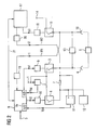
- FIG. 1 shows a block diagram of a first embodiment of the invention.
- a load 5 connected to the output 4, which has actuators and sensors, is supplied with a supply direct voltage of + 24V applied to the input 1.
- This is supplied via an output driver 3.
- This is supplied by a controller 8 via a control logic 9 control signals, by means of which the output driver can be activated and deactivated. If the output driver is activated, ie permeable, output 4 is connected to input 1. If the output driver is disabled, ie switched not permeable, then the signal path is blocked via the output driver.
- a series connection of a second output driver 6 is provided with a measuring resistor 7.
- the second output driver 6 is acted upon by a control logic 10 from the controller 8 with control signals that turn the output driver 6 permeable or block. If the output driver 6 is permeable, then the output 4 is connected via the measuring resistor 7 and the conductive output driver 6 to the input side.
- an erase diode device 13 is connected, via which after switching off the load 5, a deletion or a reduction of the stored energy can be carried out at inductive loads.
- the input 1, a voltmeter 2 is connected downstream, which is provided for measuring the voltage applied to the input 1 DC supply voltage.
- the voltage measured value UM obtained by the voltmeter 2 is supplied to the controller 8. This recognizes on the basis of the voltage measurement, a presence of fluctuations in the DC supply voltage and takes into account these voltage fluctuations in the determination of fault conditions.
- One terminal of the measuring resistor 7 is connected to the positive input of a differential amplifier 11.
- the other terminal of the measuring resistor 7 is connected to the negative input of the differential amplifier. This allows a measurement of the voltage drop across the measuring resistor 7 by subtracting in the differential amplifier 11, the current signals supplied thereto from each other and the resulting difference signal is supplied to the A / D converter input 8a of the controller 8 after a suitable gain.
- a comparison of the difference signal I D takes place with predetermined, stored in a memory of the controller thresholds to a Wire break detection and an overload detection perform.
- the controller 8 If the difference signal obtained is smaller than a predetermined first threshold value, which is 20 mA, for example, then the controller 8 detects the presence of a wire break and reports the presence of a wire break to a higher-level controller. This then initiates appropriate measures. If the difference signal obtained is greater than a predetermined second threshold, which is, for example, 2.4A, then the controller 8 detects the presence of an overload and reports the presence of an overload to a higher-level control. This then initiates appropriate measures.
- a predetermined first threshold value which is 20 mA
- a predetermined second threshold which is, for example, 2.4A
- the measurement of the voltage drop at the measuring resistor 7 takes place only during short measuring time intervals. These have, for example, a duration of 1 ms.
- the intervals of successive measuring time intervals depend on the particular application and may, for example, be in the range of minutes.
- the timing is controlled by the controller 8 and is as follows:
- the controller 8 permeabilizes the output driver 6 via the drive logic 10, so that the output 4 is connected to the input 1 via the measuring resistor 7 and the output driver 6. Thereafter, in a second step, the controller 8 deactivates the output driver 3 via the drive logic 9 so that the main signal path between the input 1 and the output 4 is interrupted. In this measurement time interval occurs on the measuring resistor 7, a voltage drop, which is evaluated to provide the controller 8 a voltage drop characterizing differential signal available.
- the controller 8 supplies to the output driver 3 arranged in the main signal path a control signal which activates this again so that the load 5 present at the output 4 again via the main signal path is powered with the output driver 3 with energy. Subsequently, the controller 8 opens the output driver 6 via the drive logic 10, so that the measurement signal path is again separated.
- the measuring resistor 7 Since the measuring resistor 7 is activated only during the short measuring time intervals, the total resulting power loss is greatly reduced compared to solutions in which the measuring resistor is located in the main signal path.
- the threshold values which are stored in the controller 8 and are used for wire breakage and overload detection, can advantageously be changed by means of the operating unit 8b. This makes it possible, if necessary, to quickly and easily adapt the threshold values to operating conditions that are present in the case of an already commissioned system.
- the newly entered threshold values in the context of this parameterization are stored instead of the existing threshold values in the memory of the controller and taken into account in the evaluation.
- the voltage measurement value UM supplied by the voltmeter 2 is also used in the controller 8 to calculate the measurement error which arises due to the measuring resistor 7 at different high DC supply voltages.
- the controller 8 depending on the determined voltage measurement value UM, subjects the supplied differential signal I D , which provides information about the voltage drop across the measuring resistor 7, to a correction process by which fluctuations of the DC supply voltage present at the input 1 are compensated.
- a zero-current reference measurement is carried out in the case of a permeable output driver 3.
- the determined zero-current reference value is stored in the controller 8 and to subtract a corrected difference signal from the obtained difference signal. Due to this zero-current reference measurement, for example, errors of operational amplifiers used can be compensated.
- the reference voltage divider 12 connected to the positive input of the differential amplifier 11 causes the current measurement value to be increased with respect to 0V in order to meet the fact that the existing operational amplifiers do not amplify to 0V. The resulting from this increase error is compensated by the above-described zero-current reference measurement again.
- data 8 are stored in a memory 8c assigned to the controller 8, which data document the time profile of the current consumption of the load 5. These data are determined in the controller 8 by evaluating the difference signal supplied to it. The controller evaluates the time course of this data in order to detect in good time an aging-related failure of an actuator belonging to the load 5. If the controller 8 recognizes an impending failure of an actuator, then it forwards this impending failure to the higher-level control, which then initiates appropriate measures.
- FIG. 2 shows a block diagram of a second embodiment of the invention.
- This second embodiment relates to a safety-critical or fail-safe application, as can be done for example in cable cars, burner controls in a power plant and in presses.
- the load 5 shown is, for example, a brake of a motor, which is supplied via the control assembly shown in the figure, a DC supply voltage.
- the load 5 is connected to outputs 4 and 16 of the control module.
- control assembly shown is - to meet the required safety standard - designed two-channel, the two channels operate in parallel, independently of each other and time-synchronized.
- the first channel has a first input 1, via which the module shown, a positive DC supply voltage of + 24V is supplied, which is applied via a voltmeter 2 to an output driver 3. Furthermore, the output of the voltmeter 2 is also connected to an output driver 6, to which a measuring resistor 7 is arranged in series. The remote from the output driver 6 terminal of the measuring resistor 7 is connected to the output of the output driver 3, so that the series circuit of output driver 6 and measuring resistor 7 is arranged parallel to the output driver 3. The output of said parallel connection forms the output 4 of the control module to which the load 5 is connected.
- the output driver 6 facing the terminal of the measuring resistor 7 is connected to the positive input of a differential amplifier 11 and the remote from the output driver 6 terminal of the measuring resistor 7 to the negative input of the differential amplifier 11.
- a reference voltage divider 12 is further connected to the positive input of the differential amplifier 11.
- the output of the differential amplifier 11 is connected to the A / D converter input 8a of the first controller 8.
- the first controller 8 is supplied as input signals, the output signal I D of the differential amplifier 11, supplied by the voltmeter 2 voltage measurement UM, a supplied via the input 3 control signal and a via a first readback path W1, which has a voltage adjustment circuit 19, readback signal r1 supplied. Furthermore, the first controller 8 is contacted with the second controller 17 arranged in the second channel via a bidirectional controller interface 21.
- the first controller 8 As output signals, the first controller 8 generates a control signal s1, which is supplied to the output driver 3 via a drive logic 9, and a control signal s2, which is supplied to the output driver 6 via a drive logic 10.
- the control signals s1 and s2 serve to activate and deactivate the output drivers 3 and 6.
- the second channel is supplied via the input 14 to the supply DC voltage associated mass (0V). This is connected to the output 16 of the control module when the output driver 15 is activated. If the output driver 15 is deactivated, then the output 16 is disconnected from the input 14. The activation and deactivation of the output driver 15 is performed by the controller 17, the output driver 15th via the drive logic 18 control signals s3 supplies.
- the second controller 17 receives signals supplied to it from the first controller 8 via the bidirectional controller interface 21, as well as readback signals r2.
- the readback signals r2 are supplied to the second controller 17 via a readback path W2 in which a voltage adjustment circuit 20 is arranged.
- the read-back signals r1 fed to the first controller 8 are derived from the output 16 of the second channel.
- the read-back signals r2 fed to the second controller 17 are derived from the output 4 of the first channel. Since these readback signals contain information about the signal state at the respective output, a defective operation of the first channel is recognized by the controller 17 of the second channel and reported directly or via the controller interface 21 and the first controller 8 to the higher-level control, which then takes appropriate measures
- the controller 17 initiates a shutdown of the outputs of 6, 3 and 15 to establish the safe state.
- a faulty operation of the second channel is detected by the controller 8 of the first channel and reported directly or via the controller 17 of the second channel to the higher-level control, which then initiates appropriate action and the controller 8 initiates a shutdown of the outputs of FIG , 3 and 15 to establish the safe condition.
- the faulty operation in the other channel can therefore be recognized by the controllers, since commands supplied from the outside, for example switch-on or emergency-off commands, are supplied to the first controller 8 via the input 3 and the first controller 8 to these commands and signals a time synchronization of both controllers the second controller 17 via the controller interface 21 transmitted. Since in normal operation both controllers and thus both channels work in parallel and independently of each other in a time-synchronized manner, Each controller knows which signals must be present at the output of the other channel at a given time. If these signals are not available, then there is a reportable error.
- the device 13 connected between the outputs 4 and 16 is an erasure diode device, via which, after switching off the load 5, a reduction of the stored energy takes place.
- FIG. 2 shows the integration of an apparatus for detecting fault conditions, as already described above in connection with FIG. 1 in a safety-critical application that uses two parallel channels.
- FIG. 2 represented overall device, for example, a presence of a wire break and an overload condition in the p-channel can be detected, ie on the supply line, which leads via the output 4 to the load 5.
- a device like that in the FIG. 1 can of course also in the second channel of the device according to FIG. 2 be integrated to detect also a presence of a wire break and an overload condition in the n-channel, ie on the supply line, which leads via the output 16 to the load.
- Such a device in the second channel for reasons of clarity in the FIG. 2 not shown.
- the invention shows a way, as in automation technology, especially in the presence of decentralized output modules, the demand for a Wire break and overload detection can be met.
- the invention enables parameterization of the wire break and overload detection limits and can also be used in fail-safe applications in which digital outputs are present.
- the invention provides the opportunity to gain information about the aging process of the load associated actuators and to detect an imminent failure of an actuator in a timely manner. As a result, an exchange of the respective actuator can be made in good time, which is particularly advantageous in safety-critical applications.
Landscapes
- Testing Of Short-Circuits, Discontinuities, Leakage, Or Incorrect Line Connections (AREA)
- Emergency Protection Circuit Devices (AREA)
- Testing And Monitoring For Control Systems (AREA)
Claims (25)
- Dispositif de détection de conditions de défauts dans l'alimentation en énergie d'une charge ( 5 ), comprenant- une entrée ( 1 ) pour une tension continue d'alimentation,- une sortie ( 4 ) pour la tension continue d'alimentation,- un premier circuit (3) d'attaque de sortie monté entre l'entrée ( 1 ) et la sortie ( 4 ),- une résistance ( 7 ) de mesure, et- une première unité ( 8 ) de commande, qui est prévue pour la commande du premier circuit ( 3 ) d'attaque de sortie et à laquelle des signaux de mesure déduits de la résistance ( 7 ) de mesure sont envoyés,
caractérisé en ce que- la résistance ( 7 ) de mesure est montée en série avec un deuxième circuit ( 6 ) d'attaque de sortie,- le montage série du deuxième circuit ( 6 ) d'attaque de sortie et de la résistance ( 7 ) de mesure est monté en parallèle au premier circuit ( 3 ) d'attaque de sortie,- la première unité (8) de commande est prévue pour la commande du deuxième circuit ( 6 ) d'attaque de sortie et- la première unité ( 8 ) de commande est prévue pour activer le deuxième circuit ( 6 ) d'attaque de sortie, seulement pendant de brefs intervalles de temps de mesure, de manière à ce que la résistance ( 7 ) de mesure ne soit montée entre l'entrée ( 1 ) et la sortie ( 4 ) que pendant la durée de ces brefs intervalles de temps de mesure et pour désactiver le premier circuit ( 3 ) d'attaque de sortie pendant la durée des brefs intervalles de temps de mesure. - Dispositif suivant la revendication 1,
caractérisé en ce qu'il est prévu pour la mesure de la chute de tension aux bornes de la résistance ( 7 ) de mesure. - Dispositif suivant la revendication 2,
caractérisé en ce qu'une borne de la résistance ( 7 ) de mesure est reliée à une première entrée ( + ) d'un amplificateur ( 11 ) différentiel et l'autre borne de la résistance ( 7 ) de mesure à une deuxième entrée ( - ) de l'amplificateur différentiel et en ce que la sortie de l'amplificateur ( 11 ) différentiel est reliée à la première unité ( 8 ) de commande. - Dispositif suivant la revendication 3,
caractérisé en ce que la sortie de l'amplificateur ( 11 ) différentiel est reliée à une entrée ( 8a ) de convertisseur A/N de la première unité ( 8 ) de commande. - Dispositif suivant l'une des revendications précédentes,
caractérisé en ce que la première unité ( 8 ) de commande compare les signaux ( ID ) de différence, qui lui sont envoyés, à de valeurs de seuil prescrites pour effectuer une détection d'une rupture de fil et/ou d'une surcharge. - Dispositif suivant la revendication 5,
caractérisé en ce que les valeurs de seuil prescrites peuvent être modifiées au moyen d'une unité ( 8b ) de service reliée à la première unité ( 8 ). - Dispositif suivant l'une des revendications précédentes,
caractérisé en ce qu'il a un voltmètre ( 2 ) qui est prévu pour la mesure de la tension continue d'alimentation et qui a une sortie reliée à la première unité ( 8 ) de commande. - Dispositif suivant la revendication 7,
caractérisé en ce que la première unité ( 8 ) de commande calcule une erreur de mesure en utilisant la valeur ( UM ) de mesure de tension produite par le voltmètre ( 2 ). - Dispositif suivant l'une des revendications précédentes,
caractérisé en ce qu'il est prévu pour effectuer une mesure de référence à courant zéro. - Dispositif suivant la revendication 9,
caractérisé en ce que la première unité ( 8 ) de commande soustrait la valeur de référence à courant zéro déterminée du signal ( ID ) de différence, qui lui est envoyé. - Dispositif suivant l'une des revendications précédentes,
caractérisé en ce qu'il a une mémoire ( 8c ) qui est prévue pour la mémorisation de données qui décrivent la variation dans le temps de l'absorption du courant par la charge ( 5 ). - Dispositif suivant la revendication 11,
caractérisé en ce que la première unité ( 8 ) de commande est prévue pour l'exploitation des données mémorisées afin de détecter une défaillance imminente d'un actionneur. - Dispositif suivant l'une des revendications précédentes,
caractérisé en ce qu'il a un circuit parallèle de deux canaux, qui ont respectivement une entrée ( 1, 14 ) pour une tension continue d'alimentation, une sortie ( 4, 16 ) pour la tension continue d'alimentation, un circuit ( 3, 15 ) d'attaque de sortie monté entre l'entrée ( 1, 14 ) respective et la sortie ( 4, 16 ) respective et une unité ( 8, 17 ) respective de commande qui est prévue pour la commande du circuit ( 3, 15 ) d'attaque de sortie respective, une tension continue d'alimentation positive pouvant être appliquée à l'entrée ( 1 ) du premier canal et la masse ( OV ) associée de la tension continue d'alimentation pouvant être appliquée à l'entrée ( 14 ) du deuxième canal. - Dispositif suivant la revendication 13,
caractérisé en ce qu'il a un trajet ( W1, W2 ) de relecture, par lequel des signaux ( r1, r2 ) de relecture dérivés de la sortie ( 4, 16 ) sont transmis. - Dispositif suivant la revendication 14,
caractérisé en ce qu'il a un trajet ( W2 ) de relecture partant de la sortie ( 4 ) du premier canal et menant à l'unité ( 17 ) de commande montée dans le deuxième canal et à un trajet ( W1 ) de relecture partant de la sortie ( 16 ) du deuxième canal et allant à l'unité ( 8 ) de commande montée dans le premier canal. - Dispositif suivant la revendication 13, 14 ou 15,
caractérisé en ce que les unités ( 8, 17 ) de commande des deux canaux sont en contact l'une avec l'autre par une interface ( 21 ). - Procédé de détection de conditions d'erreurs dans l'alimentation en énergie d'une charge ( 5 ), qui est reliée par un premier circuit ( 3 ) d'attaque de sortie à une entrée ( 1 ) d'une tension continue d'alimentation, un montage série d'un deuxième circuit (6) d'attaque de sortie et d'une résistance ( 7 ) de mesure étant prévu en parallèle au premier circuit ( 3 ) d'attaque de sortie, caractérisé en ce que le deuxième circuit ( 6 ) d'attaque de sortie n'est activé que pendant de brefs intervalles de temps de mesure pour ne brancher la résistance ( 7 ) de mesure que pendant la durée de ces brefs intervalles de temps de mesure entre l'entrée ( 1 ) de la tension continue d'alimentation et la charge ( 5 ), et en ce que le premier circuit ( 3 ) d'attaque de sortie est désactivé pendant la durée des brefs intervalles de temps de mesure.
- Procédé suivant la revendication 17,
caractérisé en ce que l'on mesure la chute de tension aux bornes de la résistance ( 7 ) de mesure pendant les intervalles de temps de mesure. - Procédé suivant la revendication 18,
caractérisé en ce que l'on envoie des signaux de mesure d'une borne de la résistance ( 7 ) de mesure à une première entrée ( + ) d'un amplificateur ( 11 ) différentiel, on envoie des signaux de mesure de la deuxième borne de la résistance ( 7 ) de mesure à une deuxième entrée ( - ) d'une amplificateur ( 11 ) différentiel et on envoie les signaux ( ID ) de différence produits au moyen de l'amplificateur ( 11 ) différentiel à une première unité ( 8 ) de commande. - Procédé suivant la revendication 19,
caractérisé en ce que la première unité ( 8 ) de commande compare les signaux ( ID ) de différence à des valeurs de seuil prescrites pour effectuer une détection d'une rupture de fil et/ou d'une surcharge. - Procédé suivant l'une des revendications 17 à 20,
caractérisé en ce que l'on mesure la tension continue d'alimentation présente à l'entrée ( 1 ) et on utilise la valeur ( UM ) de mesure obtenue pour le calcul d'une erreur de mesure. - Procédé suivant l'une des revendications 17 à 21,
caractérisé en ce que l'on effectue une mesure de référence à courant zéro. - Procédé suivant la revendication 22,
caractérisé en ce que l'on soustrait la valeur de référence à courant zéro, qui a été déterminée, des signaux ( ID ) de différence, qui ont été déterminés. - Procédé suivant l'une des revendications 17 à 23,
caractérisé en ce que l'on mémorise des données décrivant la courbe dans le temps de l'absorption du courant par la charge ( 5 ). - Procédé suivant la revendication 24,
caractérisé en ce que l'on exploite les données mémorisées pour détecter une défaillance imminente d'un actionneur.
Applications Claiming Priority (4)
| Application Number | Priority Date | Filing Date | Title |
|---|---|---|---|
| DE10204056 | 2002-01-31 | ||
| DE10204056 | 2002-01-31 | ||
| DE10219748A DE10219748A1 (de) | 2002-01-31 | 2002-05-02 | Verfahren und Vorrichtung zur Detektion von Fehlerzuständen bei der Energieversorgung einer Last |
| DE10219748 | 2002-05-02 |
Publications (3)
| Publication Number | Publication Date |
|---|---|
| EP1333552A2 EP1333552A2 (fr) | 2003-08-06 |
| EP1333552A3 EP1333552A3 (fr) | 2006-05-03 |
| EP1333552B1 true EP1333552B1 (fr) | 2013-09-11 |
Family
ID=26010990
Family Applications (1)
| Application Number | Title | Priority Date | Filing Date |
|---|---|---|---|
| EP20020028626 Expired - Lifetime EP1333552B1 (fr) | 2002-01-31 | 2002-12-20 | Procédé et appareil pour la détection de conditions des défauts dans l'alimentation d'une charge |
Country Status (1)
| Country | Link |
|---|---|
| EP (1) | EP1333552B1 (fr) |
Family Cites Families (3)
| Publication number | Priority date | Publication date | Assignee | Title |
|---|---|---|---|---|
| DE4112996A1 (de) * | 1991-04-20 | 1992-10-22 | Bosch Gmbh Robert | Vorrichtung und verfahren zur funktionsueberwachung eines elektrischen verbrauchers |
| DE4210420C2 (de) * | 1992-03-30 | 1997-02-13 | Siemens Ag | Überwachungsverfahren für einen technischen Prozeß |
| DE19833984A1 (de) * | 1998-07-10 | 2000-01-13 | Ellenberger & Poensgen | Schutzschalteinrichtung |
-
2002
- 2002-12-20 EP EP20020028626 patent/EP1333552B1/fr not_active Expired - Lifetime
Also Published As
| Publication number | Publication date |
|---|---|
| EP1333552A3 (fr) | 2006-05-03 |
| EP1333552A2 (fr) | 2003-08-06 |
Similar Documents
| Publication | Publication Date | Title |
|---|---|---|
| DE19806821C2 (de) | Störungsfeststellungseinrichtung zur Feststellung einer Störung in einem Magnetventil | |
| DE69008283T2 (de) | Gerät zum Nachweis und zur Unterscheidung von funktionellen Fehlern in einer elektrischen Versorgungsschaltung. | |
| EP2980659B1 (fr) | Dispositif et procédé destinés à la surveillance et la commutation d'un circuit de charge | |
| EP1695055B1 (fr) | Dispositif de mesure, en particulier convertisseur de mesure de temperature | |
| EP1493064A2 (fr) | Appareil de coupure, protegee contre les erreurs, d'un consommateur electrique, notamment dans les installations de production industrielle | |
| EP1269274A1 (fr) | Interrupteur de securite et procede pour ajuster un mode de fonctionnement pour interrupteur de securite | |
| DE102017126754B4 (de) | Eingangsschaltung zum fehlersicheren Einlesen eines analogen Eingangssignals | |
| EP0676055B1 (fr) | Agencement de circuits permettant de surveiller une pluralite de bobines | |
| WO2004017080A1 (fr) | Procede pour surveiller au moins deux soupapes electromagnetiques d'un moteur a combustion interne faisant partie notamment d'un vehicule automobile | |
| EP1873916A2 (fr) | Circuit de sortie sécurisé doté d'un raccordement périphérique sur un seul canal pour la sortie d'un utilisateur de bus | |
| EP2546852B1 (fr) | Relais de sécurité bistable | |
| EP2434358B1 (fr) | Procédé de fonctionnement d'un système redondant et système | |
| EP1594021B1 (fr) | Dispositif de circuit et procédé de test de contacts de commutation d'un circuit numérique de sortie | |
| DE202007014753U1 (de) | Schaltung zum Überwachen, ob die Schaltschwelle eines Schaltgebers innerhalb eines vorgegebenen Toleranzbereichs liegt | |
| DE4202761C2 (de) | Schaltung zur Ansteuerung und Überwachung induktiver Lasten, insbesondere von Magnetventilen in einem Antiblockierregelsystem | |
| EP1032519B1 (fr) | Cablage pour un composant de reglage, et procede de controle de ce cablage de composant de reglage | |
| EP1333552B1 (fr) | Procédé et appareil pour la détection de conditions des défauts dans l'alimentation d'une charge | |
| EP3200033B1 (fr) | Systeme comprenant au moins deux unites peripheriques et un capteur | |
| DE102022108193A1 (de) | Schaltverstärker für Sicherheitsanwendungen und Verfahren zum Betreiben eines Schaltverstärkers für Sicherheitsanwendungen | |
| DE3510425C2 (fr) | ||
| DE10219748A1 (de) | Verfahren und Vorrichtung zur Detektion von Fehlerzuständen bei der Energieversorgung einer Last | |
| DE10040246B4 (de) | Verfahren und Vorrichtung zur Ansteuerung wenigstens eines Verbrauchers | |
| DE102020210339B4 (de) | Schaltungsanordnung und Verfahren zur Fehlererkennung | |
| EP1486791B1 (fr) | Puce semi-conductrice qui présente un dispositif de surveillance qui permet de surveiller si la puce semi-conductrice a été endommagée mécaniquement | |
| EP4016206B1 (fr) | Agencement de capteur, appareil de commande, système d'automatisation et procédé de transmission des signaux selon deux normes de communication |
Legal Events
| Date | Code | Title | Description |
|---|---|---|---|
| PUAI | Public reference made under article 153(3) epc to a published international application that has entered the european phase |
Free format text: ORIGINAL CODE: 0009012 |
|
| AK | Designated contracting states |
Designated state(s): AT BE BG CH CY CZ DE DK EE ES FI FR GB GR IE IT LI LU MC NL PT SE SI SK TR |
|
| AX | Request for extension of the european patent |
Extension state: AL LT LV MK RO |
|
| PUAL | Search report despatched |
Free format text: ORIGINAL CODE: 0009013 |
|
| AK | Designated contracting states |
Kind code of ref document: A3 Designated state(s): AT BE BG CH CY CZ DE DK EE ES FI FR GB GR IE IT LI LU MC NL PT SE SI SK TR |
|
| AX | Request for extension of the european patent |
Extension state: AL LT LV MK RO |
|
| 17P | Request for examination filed |
Effective date: 20060522 |
|
| AKX | Designation fees paid |
Designated state(s): AT CH DE ES FR GB LI |
|
| REG | Reference to a national code |
Ref country code: DE Ref legal event code: R079 Ref document number: 50215823 Country of ref document: DE Free format text: PREVIOUS MAIN CLASS: H02H0003087000 Ipc: H02H0001000000 |
|
| 17Q | First examination report despatched |
Effective date: 20111213 |
|
| RIC1 | Information provided on ipc code assigned before grant |
Ipc: H02H 1/00 20060101AFI20111207BHEP |
|
| RAP1 | Party data changed (applicant data changed or rights of an application transferred) |
Owner name: SIEMENS AKTIENGESELLSCHAFT |
|
| GRAP | Despatch of communication of intention to grant a patent |
Free format text: ORIGINAL CODE: EPIDOSNIGR1 |
|
| INTG | Intention to grant announced |
Effective date: 20130402 |
|
| GRAS | Grant fee paid |
Free format text: ORIGINAL CODE: EPIDOSNIGR3 |
|
| GRAA | (expected) grant |
Free format text: ORIGINAL CODE: 0009210 |
|
| AK | Designated contracting states |
Kind code of ref document: B1 Designated state(s): AT CH DE ES FR GB LI |
|
| REG | Reference to a national code |
Ref country code: GB Ref legal event code: FG4D Free format text: NOT ENGLISH |
|
| REG | Reference to a national code |
Ref country code: CH Ref legal event code: EP |
|
| REG | Reference to a national code |
Ref country code: AT Ref legal event code: REF Ref document number: 632082 Country of ref document: AT Kind code of ref document: T Effective date: 20130915 |
|
| REG | Reference to a national code |
Ref country code: DE Ref legal event code: R096 Ref document number: 50215823 Country of ref document: DE Effective date: 20131031 |
|
| RAP2 | Party data changed (patent owner data changed or rights of a patent transferred) |
Owner name: SIEMENS AKTIENGESELLSCHAFT |
|
| PG25 | Lapsed in a contracting state [announced via postgrant information from national office to epo] |
Ref country code: ES Free format text: LAPSE BECAUSE OF FAILURE TO SUBMIT A TRANSLATION OF THE DESCRIPTION OR TO PAY THE FEE WITHIN THE PRESCRIBED TIME-LIMIT Effective date: 20130911 |
|
| REG | Reference to a national code |
Ref country code: DE Ref legal event code: R097 Ref document number: 50215823 Country of ref document: DE |
|
| PLBE | No opposition filed within time limit |
Free format text: ORIGINAL CODE: 0009261 |
|
| STAA | Information on the status of an ep patent application or granted ep patent |
Free format text: STATUS: NO OPPOSITION FILED WITHIN TIME LIMIT |
|
| REG | Reference to a national code |
Ref country code: CH Ref legal event code: PL |
|
| 26N | No opposition filed |
Effective date: 20140612 |
|
| REG | Reference to a national code |
Ref country code: DE Ref legal event code: R097 Ref document number: 50215823 Country of ref document: DE Effective date: 20140612 |
|
| PG25 | Lapsed in a contracting state [announced via postgrant information from national office to epo] |
Ref country code: LI Free format text: LAPSE BECAUSE OF NON-PAYMENT OF DUE FEES Effective date: 20131231 Ref country code: CH Free format text: LAPSE BECAUSE OF NON-PAYMENT OF DUE FEES Effective date: 20131231 |
|
| REG | Reference to a national code |
Ref country code: AT Ref legal event code: MM01 Ref document number: 632082 Country of ref document: AT Kind code of ref document: T Effective date: 20131220 |
|
| PG25 | Lapsed in a contracting state [announced via postgrant information from national office to epo] |
Ref country code: AT Free format text: LAPSE BECAUSE OF NON-PAYMENT OF DUE FEES Effective date: 20131220 |
|
| REG | Reference to a national code |
Ref country code: FR Ref legal event code: PLFP Year of fee payment: 14 |
|
| REG | Reference to a national code |
Ref country code: FR Ref legal event code: PLFP Year of fee payment: 15 |
|
| REG | Reference to a national code |
Ref country code: FR Ref legal event code: PLFP Year of fee payment: 16 |
|
| PGFP | Annual fee paid to national office [announced via postgrant information from national office to epo] |
Ref country code: FR Payment date: 20211217 Year of fee payment: 20 |
|
| PGFP | Annual fee paid to national office [announced via postgrant information from national office to epo] |
Ref country code: GB Payment date: 20220117 Year of fee payment: 20 Ref country code: DE Payment date: 20220218 Year of fee payment: 20 |
|
| REG | Reference to a national code |
Ref country code: DE Ref legal event code: R071 Ref document number: 50215823 Country of ref document: DE |
|
| REG | Reference to a national code |
Ref country code: GB Ref legal event code: PE20 Expiry date: 20221219 |
|
| PG25 | Lapsed in a contracting state [announced via postgrant information from national office to epo] |
Ref country code: GB Free format text: LAPSE BECAUSE OF EXPIRATION OF PROTECTION Effective date: 20221219 |