EP1333552B1 - Method and apparatus for fault condition detection in the power supply to a load - Google Patents
Method and apparatus for fault condition detection in the power supply to a load Download PDFInfo
- Publication number
- EP1333552B1 EP1333552B1 EP20020028626 EP02028626A EP1333552B1 EP 1333552 B1 EP1333552 B1 EP 1333552B1 EP 20020028626 EP20020028626 EP 20020028626 EP 02028626 A EP02028626 A EP 02028626A EP 1333552 B1 EP1333552 B1 EP 1333552B1
- Authority
- EP
- European Patent Office
- Prior art keywords
- controller
- output
- input
- output driver
- measuring resistor
- Prior art date
- Legal status (The legal status is an assumption and is not a legal conclusion. Google has not performed a legal analysis and makes no representation as to the accuracy of the status listed.)
- Expired - Lifetime
Links
- 238000001514 detection method Methods 0.000 title claims description 20
- 238000000034 method Methods 0.000 title claims description 16
- 238000005259 measurement Methods 0.000 claims description 28
- 230000003213 activating effect Effects 0.000 claims 1
- 238000010586 diagram Methods 0.000 description 4
- 238000012544 monitoring process Methods 0.000 description 4
- 230000008569 process Effects 0.000 description 4
- 230000032683 aging Effects 0.000 description 3
- 230000008901 benefit Effects 0.000 description 3
- 230000001681 protective effect Effects 0.000 description 3
- 230000002457 bidirectional effect Effects 0.000 description 2
- 230000001419 dependent effect Effects 0.000 description 2
- 230000020169 heat generation Effects 0.000 description 2
- 230000009467 reduction Effects 0.000 description 2
- 230000009471 action Effects 0.000 description 1
- 230000004913 activation Effects 0.000 description 1
- 230000000712 assembly Effects 0.000 description 1
- 238000000429 assembly Methods 0.000 description 1
- 238000012937 correction Methods 0.000 description 1
- 230000009849 deactivation Effects 0.000 description 1
- 230000002950 deficient Effects 0.000 description 1
- 238000012217 deletion Methods 0.000 description 1
- 230000037430 deletion Effects 0.000 description 1
- 238000011161 development Methods 0.000 description 1
- 230000018109 developmental process Effects 0.000 description 1
- 230000000694 effects Effects 0.000 description 1
- 238000011156 evaluation Methods 0.000 description 1
- 230000001939 inductive effect Effects 0.000 description 1
- 230000010354 integration Effects 0.000 description 1
- 238000012986 modification Methods 0.000 description 1
- 230000004048 modification Effects 0.000 description 1
- 230000002093 peripheral effect Effects 0.000 description 1
- 238000010972 statistical evaluation Methods 0.000 description 1
Images

Classifications
-
- H—ELECTRICITY
- H02—GENERATION; CONVERSION OR DISTRIBUTION OF ELECTRIC POWER
- H02H—EMERGENCY PROTECTIVE CIRCUIT ARRANGEMENTS
- H02H1/00—Details of emergency protective circuit arrangements
- H02H1/0007—Details of emergency protective circuit arrangements concerning the detecting means
-
- H—ELECTRICITY
- H02—GENERATION; CONVERSION OR DISTRIBUTION OF ELECTRIC POWER
- H02H—EMERGENCY PROTECTIVE CIRCUIT ARRANGEMENTS
- H02H1/00—Details of emergency protective circuit arrangements
- H02H1/0038—Details of emergency protective circuit arrangements concerning the connection of the detecting means, e.g. for reducing their number
-
- H—ELECTRICITY
- H02—GENERATION; CONVERSION OR DISTRIBUTION OF ELECTRIC POWER
- H02H—EMERGENCY PROTECTIVE CIRCUIT ARRANGEMENTS
- H02H3/00—Emergency protective circuit arrangements for automatic disconnection directly responsive to an undesired change from normal electric working condition with or without subsequent reconnection ; integrated protection
- H02H3/08—Emergency protective circuit arrangements for automatic disconnection directly responsive to an undesired change from normal electric working condition with or without subsequent reconnection ; integrated protection responsive to excess current
- H02H3/087—Emergency protective circuit arrangements for automatic disconnection directly responsive to an undesired change from normal electric working condition with or without subsequent reconnection ; integrated protection responsive to excess current for DC applications
-
- H—ELECTRICITY
- H02—GENERATION; CONVERSION OR DISTRIBUTION OF ELECTRIC POWER
- H02H—EMERGENCY PROTECTIVE CIRCUIT ARRANGEMENTS
- H02H5/00—Emergency protective circuit arrangements for automatic disconnection directly responsive to an undesired change from normal non-electric working conditions with or without subsequent reconnection
- H02H5/10—Emergency protective circuit arrangements for automatic disconnection directly responsive to an undesired change from normal non-electric working conditions with or without subsequent reconnection responsive to mechanical injury, e.g. rupture of line, breakage of earth connection
Definitions
- the invention relates to a method and a device for detecting fault conditions in the power supply of a load.
- a technical system monitoring and controlling automation system which transmits messages about errors in the technical process to a higher-level observation system. This evaluates the errors from us this represents by means of a display device graphically. If an error occurs in the automation itself, such as a wire break of a peripheral connection, then such an error is also graphically displayed in its effects, for example by colored marking or flashing of the system part, where the error occurred. In addition, a message text can be displayed on the screen and printed out by means of a printer as an error list. In the graphic representation of the fault location, use is made of configuration data from a configuration data memory, wherein these data are read out and processed by a processor. Information about how the presence of a wire break is detected in the DE 42 10 420 C2 not specified.
- a protective switching device with at least two running between an operating voltage input and a switching output for a load current paths known.
- an electronic switch is provided in each rung, which is connected to a control system for monitoring and all-pole shutdown of the load circuit.
- characteristic operating parameters such as, for example, their leakage current or voltage level, as well as the load current flowing over the or each current path, are used in particular for the switching state of the electronic switches.
- a measuring resistor arranged in the current path itself is used, which is connected via signal lines to a control system.
- the control system monitors the deviation of the current detected in at least one current path from a reference value. If, in the switched-off state, the load of the leakage current flowing through the switch (s) falls below a minimum current value or falls below a lower limit in the switched-on state of the load, a wire break is detected in the load circuit. Alternatively, a voltage level may also be measured and compared to a corresponding minimum level. Furthermore, in the switched-on state of the load in the event of a deviation of the load current detected in at least one current path from a predetermined reference value, an overload state is detected.
- a disadvantage of the DE 198 33 984 A1 known protective switching device is that the measuring resistor used is arranged in the current path itself. This results in normal operation of the protective switching device to an undesirable heat generation or power loss.
- the object of the invention is to show a way to reduce unwanted power loss.
- the advantages of the invention are, in particular, that due to the parallel connection of the measuring resistor to the "normal" signal path during normal operation of the device, no permanent heat generation takes place in the measuring resistor, so that the overall resulting power loss is reduced.
- the signal path via the measuring resistor is only permeable during short measuring time intervals.
- the time intervals between successive measuring time intervals are dependent on the particular application and may, for example, be in the range of minutes.
- a measuring time interval itself can be, for example, 1 ms.
- the power loss resulting in these short measuring time intervals is negligibly small.
- the invention allows a parameterization of the wire break and overload detection limits in the presence of a digital output. Furthermore, the invention offers the possibility of being able to be integrated into a fail-safe output or of being used in automation technology, in particular in connection with a decentralized arrangement of assemblies to be supplied with energy. For example, the invention is suitable for performing a wire break and overload detection in output modules.
- the invention also opens up the possibility of carrying out a statistical evaluation of the aging of an actuator by storing the measured current values. This allows early detection of an impending failure of an actor. This is a big advantage in practice, Since about 50% of dangerous failures in a safety circuit are due to a failure of actuators.
- the measurement error caused by the measuring resistor at different high DC supply voltages can be calculated and taken into account.
- a zero-current reference measurement is performed.
- the measured zero-current reference value is subtracted from the respective measured value.
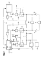
- FIG. 1 shows a block diagram of a first embodiment of the invention.
- a load 5 connected to the output 4, which has actuators and sensors, is supplied with a supply direct voltage of + 24V applied to the input 1.
- This is supplied via an output driver 3.
- This is supplied by a controller 8 via a control logic 9 control signals, by means of which the output driver can be activated and deactivated. If the output driver is activated, ie permeable, output 4 is connected to input 1. If the output driver is disabled, ie switched not permeable, then the signal path is blocked via the output driver.
- a series connection of a second output driver 6 is provided with a measuring resistor 7.
- the second output driver 6 is acted upon by a control logic 10 from the controller 8 with control signals that turn the output driver 6 permeable or block. If the output driver 6 is permeable, then the output 4 is connected via the measuring resistor 7 and the conductive output driver 6 to the input side.
- an erase diode device 13 is connected, via which after switching off the load 5, a deletion or a reduction of the stored energy can be carried out at inductive loads.
- the input 1, a voltmeter 2 is connected downstream, which is provided for measuring the voltage applied to the input 1 DC supply voltage.
- the voltage measured value UM obtained by the voltmeter 2 is supplied to the controller 8. This recognizes on the basis of the voltage measurement, a presence of fluctuations in the DC supply voltage and takes into account these voltage fluctuations in the determination of fault conditions.
- One terminal of the measuring resistor 7 is connected to the positive input of a differential amplifier 11.
- the other terminal of the measuring resistor 7 is connected to the negative input of the differential amplifier. This allows a measurement of the voltage drop across the measuring resistor 7 by subtracting in the differential amplifier 11, the current signals supplied thereto from each other and the resulting difference signal is supplied to the A / D converter input 8a of the controller 8 after a suitable gain.
- a comparison of the difference signal I D takes place with predetermined, stored in a memory of the controller thresholds to a Wire break detection and an overload detection perform.
- the controller 8 If the difference signal obtained is smaller than a predetermined first threshold value, which is 20 mA, for example, then the controller 8 detects the presence of a wire break and reports the presence of a wire break to a higher-level controller. This then initiates appropriate measures. If the difference signal obtained is greater than a predetermined second threshold, which is, for example, 2.4A, then the controller 8 detects the presence of an overload and reports the presence of an overload to a higher-level control. This then initiates appropriate measures.
- a predetermined first threshold value which is 20 mA
- a predetermined second threshold which is, for example, 2.4A
- the measurement of the voltage drop at the measuring resistor 7 takes place only during short measuring time intervals. These have, for example, a duration of 1 ms.
- the intervals of successive measuring time intervals depend on the particular application and may, for example, be in the range of minutes.
- the timing is controlled by the controller 8 and is as follows:
- the controller 8 permeabilizes the output driver 6 via the drive logic 10, so that the output 4 is connected to the input 1 via the measuring resistor 7 and the output driver 6. Thereafter, in a second step, the controller 8 deactivates the output driver 3 via the drive logic 9 so that the main signal path between the input 1 and the output 4 is interrupted. In this measurement time interval occurs on the measuring resistor 7, a voltage drop, which is evaluated to provide the controller 8 a voltage drop characterizing differential signal available.
- the controller 8 supplies to the output driver 3 arranged in the main signal path a control signal which activates this again so that the load 5 present at the output 4 again via the main signal path is powered with the output driver 3 with energy. Subsequently, the controller 8 opens the output driver 6 via the drive logic 10, so that the measurement signal path is again separated.
- the measuring resistor 7 Since the measuring resistor 7 is activated only during the short measuring time intervals, the total resulting power loss is greatly reduced compared to solutions in which the measuring resistor is located in the main signal path.
- the threshold values which are stored in the controller 8 and are used for wire breakage and overload detection, can advantageously be changed by means of the operating unit 8b. This makes it possible, if necessary, to quickly and easily adapt the threshold values to operating conditions that are present in the case of an already commissioned system.
- the newly entered threshold values in the context of this parameterization are stored instead of the existing threshold values in the memory of the controller and taken into account in the evaluation.
- the voltage measurement value UM supplied by the voltmeter 2 is also used in the controller 8 to calculate the measurement error which arises due to the measuring resistor 7 at different high DC supply voltages.
- the controller 8 depending on the determined voltage measurement value UM, subjects the supplied differential signal I D , which provides information about the voltage drop across the measuring resistor 7, to a correction process by which fluctuations of the DC supply voltage present at the input 1 are compensated.
- a zero-current reference measurement is carried out in the case of a permeable output driver 3.
- the determined zero-current reference value is stored in the controller 8 and to subtract a corrected difference signal from the obtained difference signal. Due to this zero-current reference measurement, for example, errors of operational amplifiers used can be compensated.
- the reference voltage divider 12 connected to the positive input of the differential amplifier 11 causes the current measurement value to be increased with respect to 0V in order to meet the fact that the existing operational amplifiers do not amplify to 0V. The resulting from this increase error is compensated by the above-described zero-current reference measurement again.
- data 8 are stored in a memory 8c assigned to the controller 8, which data document the time profile of the current consumption of the load 5. These data are determined in the controller 8 by evaluating the difference signal supplied to it. The controller evaluates the time course of this data in order to detect in good time an aging-related failure of an actuator belonging to the load 5. If the controller 8 recognizes an impending failure of an actuator, then it forwards this impending failure to the higher-level control, which then initiates appropriate measures.
- FIG. 2 shows a block diagram of a second embodiment of the invention.
- This second embodiment relates to a safety-critical or fail-safe application, as can be done for example in cable cars, burner controls in a power plant and in presses.
- the load 5 shown is, for example, a brake of a motor, which is supplied via the control assembly shown in the figure, a DC supply voltage.
- the load 5 is connected to outputs 4 and 16 of the control module.
- control assembly shown is - to meet the required safety standard - designed two-channel, the two channels operate in parallel, independently of each other and time-synchronized.
- the first channel has a first input 1, via which the module shown, a positive DC supply voltage of + 24V is supplied, which is applied via a voltmeter 2 to an output driver 3. Furthermore, the output of the voltmeter 2 is also connected to an output driver 6, to which a measuring resistor 7 is arranged in series. The remote from the output driver 6 terminal of the measuring resistor 7 is connected to the output of the output driver 3, so that the series circuit of output driver 6 and measuring resistor 7 is arranged parallel to the output driver 3. The output of said parallel connection forms the output 4 of the control module to which the load 5 is connected.
- the output driver 6 facing the terminal of the measuring resistor 7 is connected to the positive input of a differential amplifier 11 and the remote from the output driver 6 terminal of the measuring resistor 7 to the negative input of the differential amplifier 11.
- a reference voltage divider 12 is further connected to the positive input of the differential amplifier 11.
- the output of the differential amplifier 11 is connected to the A / D converter input 8a of the first controller 8.
- the first controller 8 is supplied as input signals, the output signal I D of the differential amplifier 11, supplied by the voltmeter 2 voltage measurement UM, a supplied via the input 3 control signal and a via a first readback path W1, which has a voltage adjustment circuit 19, readback signal r1 supplied. Furthermore, the first controller 8 is contacted with the second controller 17 arranged in the second channel via a bidirectional controller interface 21.
- the first controller 8 As output signals, the first controller 8 generates a control signal s1, which is supplied to the output driver 3 via a drive logic 9, and a control signal s2, which is supplied to the output driver 6 via a drive logic 10.
- the control signals s1 and s2 serve to activate and deactivate the output drivers 3 and 6.
- the second channel is supplied via the input 14 to the supply DC voltage associated mass (0V). This is connected to the output 16 of the control module when the output driver 15 is activated. If the output driver 15 is deactivated, then the output 16 is disconnected from the input 14. The activation and deactivation of the output driver 15 is performed by the controller 17, the output driver 15th via the drive logic 18 control signals s3 supplies.
- the second controller 17 receives signals supplied to it from the first controller 8 via the bidirectional controller interface 21, as well as readback signals r2.
- the readback signals r2 are supplied to the second controller 17 via a readback path W2 in which a voltage adjustment circuit 20 is arranged.
- the read-back signals r1 fed to the first controller 8 are derived from the output 16 of the second channel.
- the read-back signals r2 fed to the second controller 17 are derived from the output 4 of the first channel. Since these readback signals contain information about the signal state at the respective output, a defective operation of the first channel is recognized by the controller 17 of the second channel and reported directly or via the controller interface 21 and the first controller 8 to the higher-level control, which then takes appropriate measures
- the controller 17 initiates a shutdown of the outputs of 6, 3 and 15 to establish the safe state.
- a faulty operation of the second channel is detected by the controller 8 of the first channel and reported directly or via the controller 17 of the second channel to the higher-level control, which then initiates appropriate action and the controller 8 initiates a shutdown of the outputs of FIG , 3 and 15 to establish the safe condition.
- the faulty operation in the other channel can therefore be recognized by the controllers, since commands supplied from the outside, for example switch-on or emergency-off commands, are supplied to the first controller 8 via the input 3 and the first controller 8 to these commands and signals a time synchronization of both controllers the second controller 17 via the controller interface 21 transmitted. Since in normal operation both controllers and thus both channels work in parallel and independently of each other in a time-synchronized manner, Each controller knows which signals must be present at the output of the other channel at a given time. If these signals are not available, then there is a reportable error.
- the device 13 connected between the outputs 4 and 16 is an erasure diode device, via which, after switching off the load 5, a reduction of the stored energy takes place.
- FIG. 2 shows the integration of an apparatus for detecting fault conditions, as already described above in connection with FIG. 1 in a safety-critical application that uses two parallel channels.
- FIG. 2 represented overall device, for example, a presence of a wire break and an overload condition in the p-channel can be detected, ie on the supply line, which leads via the output 4 to the load 5.
- a device like that in the FIG. 1 can of course also in the second channel of the device according to FIG. 2 be integrated to detect also a presence of a wire break and an overload condition in the n-channel, ie on the supply line, which leads via the output 16 to the load.
- Such a device in the second channel for reasons of clarity in the FIG. 2 not shown.
- the invention shows a way, as in automation technology, especially in the presence of decentralized output modules, the demand for a Wire break and overload detection can be met.
- the invention enables parameterization of the wire break and overload detection limits and can also be used in fail-safe applications in which digital outputs are present.
- the invention provides the opportunity to gain information about the aging process of the load associated actuators and to detect an imminent failure of an actuator in a timely manner. As a result, an exchange of the respective actuator can be made in good time, which is particularly advantageous in safety-critical applications.
Landscapes
- Testing Of Short-Circuits, Discontinuities, Leakage, Or Incorrect Line Connections (AREA)
- Emergency Protection Circuit Devices (AREA)
- Testing And Monitoring For Control Systems (AREA)
Description
Die Erfindung betrifft ein Verfahren und eine Vorrichtung zur Detektion von Fehlerzuständen bei der Energieversorgung einer Last.The invention relates to a method and a device for detecting fault conditions in the power supply of a load.
Es ist bereits bekannt, eine Drahtbrucherkennung und/oder eine Überlasterkennung dadurch zu realisieren, dass integrierte Ausgangstreiber verwendet werden, die die Drahtbrucherkennung und die Überlasterkennung "on chip" haben. Bei diesen Ausgangstreibern ist es nicht möglich, die Drahtbruch- bzw. Überlasterkennung zu parametrieren und den Verlauf der Stromaufnahme des Aktors bzw. der Last zu dokumentieren.It is already known to realize an open-circuit detection and / or an overload detection by using integrated output drivers which have the open-circuit detection and the overload detection "on-chip". With these output drivers, it is not possible to parameterize the wire break or overload detection and to document the course of the current consumption of the actuator or the load.
Aus der
Aus der
Ein Nachteil der aus der
Die Aufgabe der Erfindung besteht darin, einen Weg zur Reduzierung unerwünschter Verlustleistung aufzuzeigen.The object of the invention is to show a way to reduce unwanted power loss.
Diese Aufgabe wird durch eine Vorrichtung mit den im Anspruch 1 und durch ein Verfahren mit den im Anspruch 18 angegebenen Merkmalen gelöst. Vorteilhafte Ausgestaltungen und Weiterbildungen der Erfindung ergeben sich aus den abhängigen Ansprüchen.This object is achieved by a device having the features specified in claim 1 and by a method having the features specified in
Die Vorteile der Erfindung bestehen insbesondere darin, dass aufgrund der Parallelschaltung des Messwiderstandes zum "normalen" Signalweg im Normalbetrieb der Vorrichtung keine permanente Wärmebildung im Messwiderstand erfolgt, so dass die insgesamt entstehende Verlustleistung reduziert ist. Der Signalweg über den Messwiderstand wird nur während kurzer Messzeitintervalle durchlässig geschaltet. Die Zeitabstände zwischen aufeinanderfolgenden Messzeitintervallen sind vom jeweiligen Anwendungsfall abhängig und können beispielsweise im Minutenbereich liegen. Ein Messzeitintervall selbst kann beispielsweise 1 ms betragen. Die in diesen kurzen Messzeitintervallen entstehende Verlustleistung ist vernachlässigbar klein.The advantages of the invention are, in particular, that due to the parallel connection of the measuring resistor to the "normal" signal path during normal operation of the device, no permanent heat generation takes place in the measuring resistor, so that the overall resulting power loss is reduced. The signal path via the measuring resistor is only permeable during short measuring time intervals. The time intervals between successive measuring time intervals are dependent on the particular application and may, for example, be in the range of minutes. A measuring time interval itself can be, for example, 1 ms. The power loss resulting in these short measuring time intervals is negligibly small.
Weitere Vorteile der Erfindung bestehen darin, dass sie beim Vorliegen eines digitalen Ausgangs eine Parametrierung der Drahtbruch- und Überlasterkennungsgrenzen zulässt. Weiterhin bietet die Erfindung die Möglichkeit, in einen fehlersicheren Ausgang integrierbar zu sein bzw. in der Automatisierungstechnik verwendbar zu sein, insbesondere im Zusammenhang mit einer dezentralen Anordnung von mit Energie zu versorgenden Baugruppen. Beispielsweise ist die Erfindung dazu geeignet, bei Ausgabebaugruppen eine Drahtbruch- und Überlasterkennung durchzuführen.Further advantages of the invention are that it allows a parameterization of the wire break and overload detection limits in the presence of a digital output. Furthermore, the invention offers the possibility of being able to be integrated into a fail-safe output or of being used in automation technology, in particular in connection with a decentralized arrangement of assemblies to be supplied with energy. For example, the invention is suitable for performing a wire break and overload detection in output modules.
Weiterhin eröffnet die Erfindung auch die Möglichkeit, durch ein Abspeichern der gemessenen Stromwerte eine statistische Auswertung der Alterung eines Aktors vorzunehmen. Dies erlaubt ein frühzeitiges Erkennen eines bevorstehenden Ausfalls eines Aktors. Dies bedeutet für die Praxis einen großen Vorteil, da ca. 50% der gefährlichen Ausfälle in einem Sicherheitskreis auf einen Ausfall von Aktoren zurückzuführen sind.Furthermore, the invention also opens up the possibility of carrying out a statistical evaluation of the aging of an actuator by storing the measured current values. This allows early detection of an impending failure of an actor. This is a big advantage in practice, Since about 50% of dangerous failures in a safety circuit are due to a failure of actuators.
Wird eine Messung der gelieferten Versorgungsgleichspannung durchgeführt, dann kann der Messfehler, der durch den Messwiderstand bei unterschiedlich hohen Versorgungsgleichspannungen entsteht, berechnet und berücksichtigt werden.If a measurement of the supplied DC supply voltage is carried out, then the measurement error caused by the measuring resistor at different high DC supply voltages can be calculated and taken into account.
Zur Verbesserung der Genauigkeit der Strommessung, insbesondere bei einer Messung kleiner Ströme, wird eine Nullstrom-Referenzmessung durchgeführt. Der gemessene Nullstrom-Referenzwert wird vom jeweils erhaltenen Messwert subtrahiert. Dadurch werden in vorteilhafter Weise Fehler von verwendeten Operationsverstärkern ausgeglichen.To improve the accuracy of the current measurement, especially when measuring small currents, a zero-current reference measurement is performed. The measured zero-current reference value is subtracted from the respective measured value. As a result, errors of operational amplifiers used are compensated in an advantageous manner.
Weitere vorteilhafte Eigenschaften der Erfindung ergeben sich aus deren beispielhafter Erläuterung anhand der Figuren. Es zeigt:
- Figur 1
- ein Blockschaltbild eines ersten Ausführungsbeispiels für die Erfindung und
Figur 2- ein Blockschaltbild eines zweiten Ausführungsbeispiels für die Erfindung.
- FIG. 1
- a block diagram of a first embodiment of the invention and
- FIG. 2
- a block diagram of a second embodiment of the invention.
Die
Parallel zum Ausgangstreiber 3 ist eine Reihenschaltung eines zweiten Ausgangstreibers 6 mit einem Messwiderstand 7 vorgesehen. Der zweite Ausgangstreiber 6 wird über eine Ansteuerlogik 10 vom Controller 8 mit Steuersignalen beaufschlagt, die den Ausgangstreiber 6 durchlässig schalten oder sperren. Ist der Ausgangstreiber 6 durchlässig geschaltet, dann ist der Ausgang 4 über den Messwiderstand 7 und den leitenden Ausgangstreiber 6 mit der Eingangsseite verbunden.Parallel to the
Parallel zur Last 5 ist eine Löschdiodenvorrichtung 13 geschaltet, über welche nach einem Ausschalten der Last 5 ein Löschen bzw. ein Abbau der gespeicherten Energie bei induktiven Lasten erfolgen kann.Parallel to the
Dem Eingang 1 ist ein Spannungsmesser 2 nachgeschaltet, welcher zur Messung der am Eingang 1 anliegenden Versorgungsgleichspannung vorgesehen ist. Der vom Spannungsmesser 2 erhaltene Spannungsmesswert UM wird dem Controller 8 zugeführt. Dieser erkennt anhand des Spannungsmesswertes ein Vorliegen von Schwankungen der Versorgungsgleichspannung und berücksichtigt diese Spannungsschwankungen bei der Ermittlungen von Fehlerzuständen.The input 1, a
Ein Anschluss des Messwiderstandes 7 ist mit dem positiven Eingang eines Differenzverstärkers 11 verbunden. Der andere Anschluss des Messwiderstandes 7 ist an den negativen Eingang des Differenzverstärkers angeschlossen. Dies erlaubt eine Messung des Spannungsabfalls am Messwiderstand 7, indem im Differenzverstärker 11 die diesem zugeführten Stromsignale voneinander subtrahiert und das erhaltene Differenzsignal nach einer geeigneten Verstärkung dem A/D-Wandler-Eingang 8a des Controllers 8 zugeführt wird. Im Controller 8 erfolgt ein Vergleich des Differenzsignals ID mit vorgegebenen, in einem Speicher des Controllers hinterlegten Schwellenwerten, um eine Drahtbrucherkennung und eine Überlasterkennung durchzuführen. Ist das erhaltene Differenzsignal kleiner als ein vorgegebener erster Schwellenwert, der beispielsweise 20mA beträgt, dann erkennt der Controller 8 das Vorliegen eines Drahtbruches und meldet das Vorliegen eines Drahtbruches an eine übergeordnete Steuerung. Diese leitet dann geeignete Maßnahmen in die Wege. Ist das erhaltene Differenzsignal größer als ein vorgegebener zweiter Schwellenwert, der beispielsweise 2,4A beträgt, dann erkennt der Controller 8 das Vorliegen einer Überlast und meldet das Vorliegen einer Überlast an eine übergeordnete Steuerung. Diese leitet dann geeignete Maßnahmen in die Wege.One terminal of the
In vorteilhafter Weise erfolgt die Messung des Spannungsabfalls am Messwiderstand 7 nur während kurzer Messzeitintervalle. Diese haben beispielsweise eine Dauer von 1 ms. Die Abstände aufeinanderfolgender Messzeitintervalle sind vom jeweiligen konkreten Anwendungsfall abhängig und können beispielsweise im Minutenbereich liegen. Der zeitliche Ablauf wird durch den Controller 8 gesteuert und ist wie folgt:Advantageously, the measurement of the voltage drop at the measuring
In einem ersten Schritt schaltet der Controller 8 den Ausgangstreiber 6 über die Ansteuerlogik 10 durchlässig, so dass der Ausgang 4 über den Messwiderstand 7 und den Ausgangstreiber 6 mit dem Eingang 1 verbunden ist. Danach deaktiviert der Controller 8 in einem zweiten Schritt über die Ansteuerlogik 9 den Ausgangstreiber 3, so dass der Hauptsignalweg zwischen dem Eingang 1 und dem Ausgang 4 unterbrochen ist. In diesem Messzeitintervall tritt am Messwiderstand 7 ein Spannungsabfall auf, der ausgewertet wird, um dem Controller 8 ein den Spannungsabfall charakterisierendes Differenzsignal zur Verfügung zu stellen.In a first step, the controller 8 permeabilizes the
Ist das kurze Messzeitintervall beendet, dann führt der Controller 8 dem im Hauptsignalweg angeordneten Ausgangstreiber 3 ein diesen wieder aktivierendes Steuersignal zu, so dass die am Ausgang 4 anliegende Last 5 wieder über den Hauptsignalweg mit dem Ausgangstreiber 3 mit Energie versorgt wird. Anschließend öffnet der Controller 8 über die Ansteuerlogik 10 den Ausgangstreiber 6, so dass der Messsignalweg wieder aufgetrennt ist.If the short measuring time interval has ended, then the controller 8 supplies to the
Da der Messwiderstand 7 nur während der kurzen Messzeitintervalle aktiviert ist, ist die insgesamt entstehende Verlustleistung im Vergleich zu Lösungen, bei denen sich der Messwiderstand im Hauptsignalweg befindet, stark reduziert.Since the measuring
Die Schwellenwerte, die im Controller 8 hinterlegt sind und zur Drahtbruch- und Überlasterkennung verwendet werden, sind in vorteilhafter Weise mittels der Bedieneinheit 8b veränderbar. Dies erlaubt es, bei einer bereits in Betrieb genommenen Anlage bei Bedarf schnell und einfach eine Anpassung der Schwellenwerte an jeweils vorliegende Betriebsverhältnisse durchzuführen. Die im Rahmen dieser Parametrierung neu eingegebenen Schwellenwerte werden anstelle der vorhandenen Schwellenwerte im Speicher des Controllers hinterlegt und bei der Auswertung berücksichtigt.The threshold values, which are stored in the controller 8 and are used for wire breakage and overload detection, can advantageously be changed by means of the
Weiterhin wird im Controller 8 auch der vom Spannungsmesser 2 gelieferte Spannungsmesswert UM zur Berechnung des Messfehlers verwendet, der durch den Messwiderstand 7 bei unterschiedlich hohen Versorgungsgleichspannungen entsteht. Dies bedeutet mit anderen Worten, dass der Controller 8 in Abhängigkeit vom ermittelten Spannungsmesswert UM das im zugeführte Differenzsignal ID, das Auskunft über den Spannungsabfall am Messwiderstand 7 gibt, einem Korrekturvorgang unterwirft, durch welchen Schwankungen der am Eingang 1 vorliegenden Versorgungsgleichspannung kompensiert werden.Furthermore, the voltage measurement value UM supplied by the
Ferner wird zur Verbesserung der Genauigkeit des Messvorgangs, was insbesondere beim Vorliegen kleiner Ströme vorteilhaft ist, bei durchlässig geschaltetem Ausgangstreiber 3 eine Nullstrom-Referenzmessung durchgeführt. Der ermittelte Nullstrom-Referenzwert wird im Controller 8 abgespeichert und zum Erhalt eines korrigierten Differenzsignals vom erhaltenen Differenzsignal subtrahiert. Aufgrund dieser Nullstrom-Referenzmessung können beispielsweise Fehler verwendeter Operationsverstärker kompensiert werden.Furthermore, in order to improve the accuracy of the measuring process, which is advantageous in particular in the presence of small currents, a zero-current reference measurement is carried out in the case of a
Der mit dem positiven Eingang des Differenzverstärkers 11 verbundene Referenzspannungsteiler 12 bewirkt eine Anhebung des Strommesswertes gegenüber 0V, um der Tatsache gerecht zu werden, dass die vorhandenen Operationsverstärker nicht bis 0V verstärken. Der durch diese Anhebung entstehende Fehler wird durch die vorstehend beschriebene Nullstrom-Referenzmessung wieder ausgeglichen.The
Die vom Controller 8 im Rahmen der Drahtbruch- bzw. Überlasterkennung verwendete Formel zur Berechnung des korrigierten Stromistwertes, der mit den Schwellenwerten verglichen wird, lautet wie folgt:
- I = Strom
durch den Lastwiderstand 5 in A, - UM = Versorgungsspannung der Schaltung in V,
- Uref = Referenzspannung des A/D-
Wandlers 8a in V, - Aufl = Auflösung des A/D-
Wandlers 8a in Digit, - Wert = Messwert des Ausgangsstroms in Digit,
- Wert_zero = Messwert der Nullstrom-Referenzmessung in Digit, und
- R = Widerstandswert des Messwiderstands 7 in Ohm ist.
- I = current through the
load resistor 5 in A, - U M = supply voltage of the circuit in V,
- U ref = reference voltage of the A /
D converter 8a in V, - Resolution = resolution of the A /
D converter 8a in digit, - Value = measured value of the output current in digit,
- Value_zero = measured value of the zero current reference measurement in digit, and
- R = resistance value of the measuring
resistor 7 in ohms.
Gemäß einer vorteilhaften Weiterbildung der Erfindung werden in einem dem Controller 8 zugeordneten Speicher 8c Daten abgespeichert, die den zeitlichen Verlauf der Stromaufnahme der Last 5 dokumentieren. Diese Daten werden im Controller 8 durch Auswertung des ihm zugeführten Differenzsignals ermittelt. Der Controller wertet den zeitlichen Verlauf dieser Daten aus, um rechtzeitig einen alterungsbedingten Ausfall eines zur Last 5 gehörigen Aktors zu erkennen. Erkennt der Controller 8 einen bevorstehenden Ausfall eines Aktors, dann meldet er diesen bevorstehenden Ausfall an die übergeordnete Steuerung weiter, die dann entsprechende Maßnahmen in die Wege leitet.According to an advantageous development of the invention, data 8 are stored in a
Die
Bei der in der
Die gezeigte Steuerungsbaugruppe ist - um die geforderte Sicherheitsnorm zu erfüllen - zweikanalig ausgebildet, wobei die beiden Kanäle parallel, unabhängig voneinander und zeitsynchron arbeiten.The control assembly shown is - to meet the required safety standard - designed two-channel, the two channels operate in parallel, independently of each other and time-synchronized.
Der erste Kanal weist einen ersten Eingang 1 auf, über welchen der gezeigten Baugruppe eine positive Versorgungsgleichspannung von +24V zugeführt wird, die über einen Spannungsmesser 2 an einen Ausgangstreiber 3 angelegt ist. Weiterhin ist der Ausgang des Spannungsmessers 2 auch mit einem Ausgangstreiber 6 verbunden, zu welchem in Reihe ein Messwiderstand 7 angeordnet ist. Der vom Ausgangstreiber 6 abgewandte Anschluss des Messwiderstandes 7 ist mit dem Ausgang des Ausgangstreibers 3 verbunden, so dass die Reihenschaltung aus Ausgangstreiber 6 und Messwiderstand 7 parallel zum Ausgangstreiber 3 angeordnet ist. Der Ausgang der genannten Parallelschaltung bildet den Ausgang 4 der Steuerungsbaugruppe, an welchen die Last 5 angeschlossen ist.The first channel has a first input 1, via which the module shown, a positive DC supply voltage of + 24V is supplied, which is applied via a
Der dem Ausgangstreiber 6 zugewandte Anschluss des Messwiderstandes 7 ist mit dem positiven Eingang eines Differenzverstärkers 11 und der vom Ausgangstreiber 6 abgelegene Anschluss des Messwiderstandes 7 mit dem negativen Eingang des Differenzverstärkers 11 verbunden. An den positiven Eingang des Differenzverstärkers 11 ist weiterhin ein Referenzspannungsteiler 12 angeschlossen. Der Ausgang des Differenzverstärkers 11 ist mit dem A/D-Wandler-Eingang 8a des ersten Controllers 8 verbunden.The
Dem ersten Controller 8 werden als Eingangssignale das Ausgangssignal ID des Differenzverstärkers 11, der vom Spannungsmesser 2 gelieferte Spannungsmesswert UM, ein über den Eingang 3 angeliefertes Steuersignal und ein über einen ersten Rücklesepfad W1, der eine Spannungsanpassungsschaltung 19 aufweist, geliefertes Rücklesesignal r1 zugeführt. Weiterhin ist der erste Controller 8 mit dem im zweiten Kanal angeordneten zweiten Controller 17 über eine bidirektionale Controllerschnittstelle 21 kontaktiert.The first controller 8 is supplied as input signals, the output signal I D of the differential amplifier 11, supplied by the
Als Ausgangssignale generiert der erste Controller 8 ein Steuersignal s1, welches dem Ausgangstreiber 3 über eine Ansteuerlogik 9 zugeführt wird, sowie ein Steuersignal s2, welches dem Ausgangstreiber 6 über eine Ansteuerlogik 10 zugeführt wird. Die Steuersignale s1 und s2 dienen zum Aktivieren und Deaktivieren der Ausgangstreiber 3 und 6.As output signals, the first controller 8 generates a control signal s1, which is supplied to the
Dem zweiten Kanal wird über den Eingang 14 die zur Versorgungsgleichspannung zugehörige Masse (0V) zugeführt. Diese ist bei aktiviertem Ausgangstreiber 15 mit dem Ausgang 16 der Steuerungsbaugruppe verbunden. Ist der Ausgangstreiber 15 deaktiviert, dann ist der Ausgang 16 vom Eingang 14 abgetrennt. Die Aktivierung und Deaktivierung des Ausgangstreibers 15 erfolgt durch den Controller 17, der dem Ausgangstreiber 15 über die Ansteuerlogik 18 Steuersignale s3 zuführt.The second channel is supplied via the
Als Eingangssignale erhält der zweite Controller 17 Signale, die ihm vom ersten Controller 8 über die bidirektionale Controllerschnittstelle 21 geliefert werden, sowie Rücklesesignale r2. Die Rücklesesignale r2 werden dem zweiten Controller 17 über einen Rücklesepfad W2 zugeführt, in welchem eine Spannungsanpassungsschaltung 20 angeordnet ist.As input signals, the
Die dem ersten Controller 8 zugeleiteten Rücklesesignale r1 werden vom Ausgang 16 des zweiten Kanals abgeleitet. Die dem zweiten Controller 17 zugeleiteten Rücklesesignale r2 werden vom Ausgang 4 des ersten Kanals abgeleitet. Da diese Rücklesesignale eine Information über den Signalzustand am jeweiligen Ausgang enthalten, wird beispielsweise ein fehlerhaftes Arbeiten des ersten Kanals vom Controller 17 des zweiten Kanals erkannt und direkt oder über die Controllerschnittstelle 21 und den ersten Controller 8 an die übergeordnete Steuerung gemeldet, die dann geeignete Maßnahmen in die Wege leitet und der Controller 17 leitet ein Abschalten der Ausgänge von 6, 3 und 15 ein, um den sicheren Zustand herzustellen. Ebenso wird ein fehlerhaftes Arbeiten des zweiten Kanals vom Controller 8 des ersten Kanals erkannt und direkt oder über den Controller 17 des zweiten Kanals an die übergeordnete Steuerung gemeldet, die dann geeignete Maßnahmen in die Wege leitet und der Controller 8 leitet ein Abschalten der Ausgänge von 6, 3 und 15 ein, um den sicheren Zustand herzustellen.The read-back signals r1 fed to the first controller 8 are derived from the
Die fehlerhafte Arbeitsweise im jeweils anderen Kanal kann von den Controllern deshalb erkannt werden, da von außen zugeführte Befehle, beispielsweise Einschalt- oder Not-Aus-Befehle dem ersten Controller 8 über den Eingang 3 zugeführt werden und der erste Controller 8 diese Befehle sowie Signale zu einer Zeitsynchronisierung beider Controller dem zweiten Controller 17 über die Controllerschnittstelle 21 übermittelt. Da im Normalbetrieb beide Controller und damit beide Kanäle parallel und unabhängig zueinander zeitsynchron arbeiten, ist jedem Controller bekannt, welche Signale zu einem gegebenen Zeitpunkt am Ausgang des jeweils anderen Kanals vorliegen müssen. Liegen diese Signale nicht vor, dann liegt ein meldepflichtiger Fehler vor.The faulty operation in the other channel can therefore be recognized by the controllers, since commands supplied from the outside, for example switch-on or emergency-off commands, are supplied to the first controller 8 via the
Die zwischen die Ausgänge 4 und 16 geschaltete Vorrichtung 13 ist eine Löschdiodenvorrichtung, über welche nach einem Ausschalten der Last 5 ein Abbau der gespeicherten Energie erfolgt.The
Die
Mittels der in der
Eine Vorrichtung, wie sie in der
Nach alledem zeigt die Erfindung einen Weg, wie in der Automatisierungstechnik, insbesondere beim Vorliegen dezentral angeordneter Ausgabebaugruppen, die Forderung nach einer Drahtbruch- und einer Überlasterkennung erfüllt werden kann. Die Erfindung ermöglicht eine Parametrierung der Drahtbruch- und Überlasterkennungsgrenzen und ist auch bei fehlersicheren Anwendungen einsetzbar, bei denen digitale Ausgänge vorliegen. Weiterhin bietet die Erfindung die Möglichkeit, Aussagen über den Alterungsprozess von der Last zugehörigen Aktoren zu gewinnen und einen bevorstehenden Ausfall eines Aktors rechtzeitig zu erkennen. Dadurch kann rechtzeitig ein Austausch des jeweiligen Aktors vorgenommen werden, was insbesondere bei sicherheitskritischen Anwendungen von großem Vorteil ist.After all, the invention shows a way, as in automation technology, especially in the presence of decentralized output modules, the demand for a Wire break and overload detection can be met. The invention enables parameterization of the wire break and overload detection limits and can also be used in fail-safe applications in which digital outputs are present. Furthermore, the invention provides the opportunity to gain information about the aging process of the load associated actuators and to detect an imminent failure of an actuator in a timely manner. As a result, an exchange of the respective actuator can be made in good time, which is particularly advantageous in safety-critical applications.
Claims (25)
- Apparatus for detecting fault conditions in the energy supply of a load (5), having- an input (1) for a DC supply voltage,- an output (4) for the DC supply voltage,- a first output driver (3) arranged between the input (1) and the output (4),- a measuring resistor (3), and- a first controller (8), which is provided for controlling the first output driver (3) and to which measurement signals derived from the measuring resistor (7) are fed,
characterised in that- the measuring resistor (7) is arranged in series with a second output driver (6),- the series connection of the second output driver (6) to the measuring resistor (7) is arranged in parallel to the first output driver (3),- the first controller is provided (8) for controlling the second output driver (6), and- the first controller (8) is provided for activating the second output driver (6) only for short measuring time intervals, so that the measuring resistor (7) is connected only for the duration of these short measuring time intervals between the input (1) and the output (4), and for deactivating the first output driver (3) for the duration of the short measuring time intervals. - Apparatus according to claim 1, characterised in that it is provided for measuring the voltage drop at the measuring resistor (7).
- Apparatus according to claim 2, characterised in that one terminal of the measuring resistor (7) is connected to a first input (+) of a differential amplifier (11) and the other terminal of the measuring resistor (7) is connected to a second input (-) of the differential amplifier (11) and that the output of the differential amplifier (11) is connected to the first controller (8).
- Apparatus according to claim 3, characterised in that the output of the differential amplifier (11) is connected to an A/D converter input (8a) of the first controller (8).
- Apparatus according to one of the preceding claims, characterised in that the first controller (8) compares the differential signals (ID) fed to it with predetermined threshold values in order to perform a wire-break detection and/or an overload detection.
- Apparatus according to claim 5, characterised in that the predetermined threshold values can be varied by means of a control unit (8b) connected to the first controller (8).
- Apparatus according to one of the preceding claims, characterised in that it has a voltmeter (2) provided for measuring the DC supply voltage and with an output connected to the first controller (8).
- Apparatus according to claim 7, characterised in that the first controller (8) calculates a measurement error using the voltage measurement value (UM) generated by the voltmeter (2).
- Apparatus according to one of the preceding claims, characterised in that it is provided for performing a zero-current reference measurement.
- Apparatus according to claim 9, characterised in that the first controller (8) subtracts the determined zero-current reference value from the differential signal (ID) fed to it.
- Apparatus according to one of the preceding claims, characterised in that it has a memory (8c) which is provided for storing data describing the time progression of the current consumption of the load (5).
- Apparatus according to claim 11, characterised in that the first controller (8) is provided for evaluating the stored data, in order to identify an impending failure of an actuator.
- Apparatus according to one of the preceding claims, characterised in that it has a parallel connection of two channels, each having an input (1, 14) for a DC supply voltage, an output (4, 16) for the DC supply voltage, an output driver (3, 15) arranged between the respective input (1, 14) and the respective output (4, 16), and a respective controller (8, 17) which is provided for controlling the respective output driver (3, 15), wherein a positive DC supply voltage can be fed to the input (1) of the first channel and the associated reference potential (OV) of the DC supply voltage can be fed to the input (14) of the second channel.
- Apparatus according to claim 13, characterised in that it has a readback path (W1, W2), via which readback signals (r1, r2) derived from the output (4, 16) are transmitted.
- Apparatus according to claim 14, characterised in that it has a readback path (W2) exiting from the output (4) of the first channel and leading to the controller (17) arranged in the second channel, and a readback path (W1) exiting from the output (16) of the second channel and leading to the controller (8) arranged in the first channel.
- Apparatus according to one of claims 13, 14 or 15, characterised in that the controllers (8, 17) of the two channels are contacted with each other via an interface (21).
- Method for detecting fault conditions in the energy supply of a load (5), which is connected via a first output driver (3) to an input (1) for a DC supply voltage, wherein a series connection of a second output driver (6) to a measuring resistor (7) is provided in parallel to the first output driver (3), characterised in that the second output driver (6) is activated only for short measuring time intervals in order to connect the measurement resistor (7) only for the duration of these short measuring time intervals between the input (1) for the DC supply voltage and the load (5), and that the first output driver (3) is deactivated for the duration of the short measuring time intervals.
- Method according to claim 17, characterised in that the voltage drop at the measuring resistor (7) is measured during the measuring time intervals.
- Method according to claim 18, characterised in that measurement signals are fed to a first input (+) of a differential amplifier (11) from a terminal of the measuring resistor (7), measurement signals are fed to a second input (-) of the differential amplifier (11) from the second terminal of the measuring resistor (7) and the differential signals (ID) generated by means of the differential amplifier (11) are fed to a first controller (8).
- Method according to claim 19, characterised in that the first controller (8) compares the differential signals (ID) with predetermined threshold values in order to perform a wire-break detection and/or an overload detection.
- Method according to one of claims 17 to 20, characterised in that DC supply voltage present at the input (1) is measured and the measurement value (UM) obtained is used to calculate a measurement error.
- Method according to one of claims 17 to 21, characterised in that a zero-current reference measurement is performed.
- Method according to claim 22, characterised in that the zero-current reference value determined is subtracted from the differential signals (ID) determined.
- Method according to one of claims 17 to 23, characterised in that data describing the time progression of the current consumption of the load (5) is stored.
- Method according to claim 24, characterised in that the stored data is evaluated to detect an impending failure of an actuator.
Applications Claiming Priority (4)
| Application Number | Priority Date | Filing Date | Title |
|---|---|---|---|
| DE10204056 | 2002-01-31 | ||
| DE10204056 | 2002-01-31 | ||
| DE10219748A DE10219748A1 (en) | 2002-01-31 | 2002-05-02 | Method and device for detecting fault conditions in the energy supply of a load |
| DE10219748 | 2002-05-02 |
Publications (3)
| Publication Number | Publication Date |
|---|---|
| EP1333552A2 EP1333552A2 (en) | 2003-08-06 |
| EP1333552A3 EP1333552A3 (en) | 2006-05-03 |
| EP1333552B1 true EP1333552B1 (en) | 2013-09-11 |
Family
ID=26010990
Family Applications (1)
| Application Number | Title | Priority Date | Filing Date |
|---|---|---|---|
| EP20020028626 Expired - Lifetime EP1333552B1 (en) | 2002-01-31 | 2002-12-20 | Method and apparatus for fault condition detection in the power supply to a load |
Country Status (1)
| Country | Link |
|---|---|
| EP (1) | EP1333552B1 (en) |
Family Cites Families (3)
| Publication number | Priority date | Publication date | Assignee | Title |
|---|---|---|---|---|
| DE4112996A1 (en) * | 1991-04-20 | 1992-10-22 | Bosch Gmbh Robert | Functional monitor for electrical load controlled by switch - measures voltage and/or current of control line by fault identification circuit when fault detection circuit is activated |
| DE4210420C2 (en) * | 1992-03-30 | 1997-02-13 | Siemens Ag | Monitoring process for a technical process |
| DE19833984A1 (en) * | 1998-07-10 | 2000-01-13 | Ellenberger & Poensgen | Protection switching device |
-
2002
- 2002-12-20 EP EP20020028626 patent/EP1333552B1/en not_active Expired - Lifetime
Also Published As
| Publication number | Publication date |
|---|---|
| EP1333552A3 (en) | 2006-05-03 |
| EP1333552A2 (en) | 2003-08-06 |
Similar Documents
| Publication | Publication Date | Title |
|---|---|---|
| DE19806821C2 (en) | Fault detection device for detecting a fault in a solenoid valve | |
| DE69008283T2 (en) | Device for the detection and differentiation of functional errors in an electrical supply circuit. | |
| EP2980659B1 (en) | Device and method for monitoring and switching a load circuit | |
| EP1695055B1 (en) | Measuring device, in particular a temperature measuring transducer | |
| EP1493064A2 (en) | Device for the error-proof switching off of an electric consumer, particularly in industrial production plants | |
| EP1269274A1 (en) | Safety switching unit and method for setting an operational mode of a safety switching unit | |
| DE102017126754B4 (en) | Input circuit for fail-safe reading of an analog input signal | |
| EP0676055B1 (en) | Circuit arrangement for monitoring a plurality of coils | |
| WO2004017080A1 (en) | Method for monitoring at least two electromagnetic valves of an internal combustion engine, especially an internal combustion engine of a motor vehicle | |
| EP1873916A2 (en) | Secure output circuit with a single channel periphery connection for the output of a bus participant | |
| EP2546852B1 (en) | Bi-stable security relay | |
| EP2434358B1 (en) | System and method for operating a redundant system | |
| EP1594021B1 (en) | Circuit device and method for testing relay switching contacts of a digital output circuit | |
| DE202007014753U1 (en) | Circuit for monitoring whether the switching threshold of a switching sensor is within a predetermined tolerance range | |
| DE4202761C2 (en) | Circuit for the control and monitoring of inductive loads, especially of solenoid valves in an anti-lock control system | |
| EP1032519B1 (en) | Protective circuit for a controlling element and method for testing the control circuit of a controlling element | |
| EP1333552B1 (en) | Method and apparatus for fault condition detection in the power supply to a load | |
| EP3200033B1 (en) | Assembly comprising at least two peripheral units with a sensor | |
| DE102022108193A1 (en) | Switching amplifier for security applications and method for operating a switching amplifier for security applications | |
| DE3510425C2 (en) | ||
| DE10219748A1 (en) | Method and device for detecting fault conditions in the energy supply of a load | |
| DE10040246B4 (en) | Method and device for controlling at least one consumer | |
| DE102020210339B4 (en) | Circuit arrangement and method for error detection | |
| EP1486791B1 (en) | Semiconductor chip, comprising a monitoring device, which can be used to monitor whether the semiconductor chip is mechanically damaged | |
| EP4016206B1 (en) | Sensor arrangement, control device, automation system and method for transmitting signals according to two communication standards |
Legal Events
| Date | Code | Title | Description |
|---|---|---|---|
| PUAI | Public reference made under article 153(3) epc to a published international application that has entered the european phase |
Free format text: ORIGINAL CODE: 0009012 |
|
| AK | Designated contracting states |
Designated state(s): AT BE BG CH CY CZ DE DK EE ES FI FR GB GR IE IT LI LU MC NL PT SE SI SK TR |
|
| AX | Request for extension of the european patent |
Extension state: AL LT LV MK RO |
|
| PUAL | Search report despatched |
Free format text: ORIGINAL CODE: 0009013 |
|
| AK | Designated contracting states |
Kind code of ref document: A3 Designated state(s): AT BE BG CH CY CZ DE DK EE ES FI FR GB GR IE IT LI LU MC NL PT SE SI SK TR |
|
| AX | Request for extension of the european patent |
Extension state: AL LT LV MK RO |
|
| 17P | Request for examination filed |
Effective date: 20060522 |
|
| AKX | Designation fees paid |
Designated state(s): AT CH DE ES FR GB LI |
|
| REG | Reference to a national code |
Ref country code: DE Ref legal event code: R079 Ref document number: 50215823 Country of ref document: DE Free format text: PREVIOUS MAIN CLASS: H02H0003087000 Ipc: H02H0001000000 |
|
| 17Q | First examination report despatched |
Effective date: 20111213 |
|
| RIC1 | Information provided on ipc code assigned before grant |
Ipc: H02H 1/00 20060101AFI20111207BHEP |
|
| RAP1 | Party data changed (applicant data changed or rights of an application transferred) |
Owner name: SIEMENS AKTIENGESELLSCHAFT |
|
| GRAP | Despatch of communication of intention to grant a patent |
Free format text: ORIGINAL CODE: EPIDOSNIGR1 |
|
| INTG | Intention to grant announced |
Effective date: 20130402 |
|
| GRAS | Grant fee paid |
Free format text: ORIGINAL CODE: EPIDOSNIGR3 |
|
| GRAA | (expected) grant |
Free format text: ORIGINAL CODE: 0009210 |
|
| AK | Designated contracting states |
Kind code of ref document: B1 Designated state(s): AT CH DE ES FR GB LI |
|
| REG | Reference to a national code |
Ref country code: GB Ref legal event code: FG4D Free format text: NOT ENGLISH |
|
| REG | Reference to a national code |
Ref country code: CH Ref legal event code: EP |
|
| REG | Reference to a national code |
Ref country code: AT Ref legal event code: REF Ref document number: 632082 Country of ref document: AT Kind code of ref document: T Effective date: 20130915 |
|
| REG | Reference to a national code |
Ref country code: DE Ref legal event code: R096 Ref document number: 50215823 Country of ref document: DE Effective date: 20131031 |
|
| RAP2 | Party data changed (patent owner data changed or rights of a patent transferred) |
Owner name: SIEMENS AKTIENGESELLSCHAFT |
|
| PG25 | Lapsed in a contracting state [announced via postgrant information from national office to epo] |
Ref country code: ES Free format text: LAPSE BECAUSE OF FAILURE TO SUBMIT A TRANSLATION OF THE DESCRIPTION OR TO PAY THE FEE WITHIN THE PRESCRIBED TIME-LIMIT Effective date: 20130911 |
|
| REG | Reference to a national code |
Ref country code: DE Ref legal event code: R097 Ref document number: 50215823 Country of ref document: DE |
|
| PLBE | No opposition filed within time limit |
Free format text: ORIGINAL CODE: 0009261 |
|
| STAA | Information on the status of an ep patent application or granted ep patent |
Free format text: STATUS: NO OPPOSITION FILED WITHIN TIME LIMIT |
|
| REG | Reference to a national code |
Ref country code: CH Ref legal event code: PL |
|
| 26N | No opposition filed |
Effective date: 20140612 |
|
| REG | Reference to a national code |
Ref country code: DE Ref legal event code: R097 Ref document number: 50215823 Country of ref document: DE Effective date: 20140612 |
|
| PG25 | Lapsed in a contracting state [announced via postgrant information from national office to epo] |
Ref country code: LI Free format text: LAPSE BECAUSE OF NON-PAYMENT OF DUE FEES Effective date: 20131231 Ref country code: CH Free format text: LAPSE BECAUSE OF NON-PAYMENT OF DUE FEES Effective date: 20131231 |
|
| REG | Reference to a national code |
Ref country code: AT Ref legal event code: MM01 Ref document number: 632082 Country of ref document: AT Kind code of ref document: T Effective date: 20131220 |
|
| PG25 | Lapsed in a contracting state [announced via postgrant information from national office to epo] |
Ref country code: AT Free format text: LAPSE BECAUSE OF NON-PAYMENT OF DUE FEES Effective date: 20131220 |
|
| REG | Reference to a national code |
Ref country code: FR Ref legal event code: PLFP Year of fee payment: 14 |
|
| REG | Reference to a national code |
Ref country code: FR Ref legal event code: PLFP Year of fee payment: 15 |
|
| REG | Reference to a national code |
Ref country code: FR Ref legal event code: PLFP Year of fee payment: 16 |
|
| PGFP | Annual fee paid to national office [announced via postgrant information from national office to epo] |
Ref country code: FR Payment date: 20211217 Year of fee payment: 20 |
|
| PGFP | Annual fee paid to national office [announced via postgrant information from national office to epo] |
Ref country code: GB Payment date: 20220117 Year of fee payment: 20 Ref country code: DE Payment date: 20220218 Year of fee payment: 20 |
|
| REG | Reference to a national code |
Ref country code: DE Ref legal event code: R071 Ref document number: 50215823 Country of ref document: DE |
|
| REG | Reference to a national code |
Ref country code: GB Ref legal event code: PE20 Expiry date: 20221219 |
|
| PG25 | Lapsed in a contracting state [announced via postgrant information from national office to epo] |
Ref country code: GB Free format text: LAPSE BECAUSE OF EXPIRATION OF PROTECTION Effective date: 20221219 |