EP1333544A1 - Durchführungsklemme für elektrische Leiter - Google Patents
Durchführungsklemme für elektrische Leiter Download PDFInfo
- Publication number
- EP1333544A1 EP1333544A1 EP03000237A EP03000237A EP1333544A1 EP 1333544 A1 EP1333544 A1 EP 1333544A1 EP 03000237 A EP03000237 A EP 03000237A EP 03000237 A EP03000237 A EP 03000237A EP 1333544 A1 EP1333544 A1 EP 1333544A1
- Authority
- EP
- European Patent Office
- Prior art keywords
- wall
- feed
- terminal housing
- opening
- housing
- Prior art date
- Legal status (The legal status is an assumption and is not a legal conclusion. Google has not performed a legal analysis and makes no representation as to the accuracy of the status listed.)
- Granted
Links
Images


Classifications
-
- H—ELECTRICITY
- H01—ELECTRIC ELEMENTS
- H01R—ELECTRICALLY-CONDUCTIVE CONNECTIONS; STRUCTURAL ASSOCIATIONS OF A PLURALITY OF MUTUALLY-INSULATED ELECTRICAL CONNECTING ELEMENTS; COUPLING DEVICES; CURRENT COLLECTORS
- H01R13/00—Details of coupling devices of the kinds covered by groups H01R12/70 or H01R24/00 - H01R33/00
- H01R13/73—Means for mounting coupling parts to apparatus or structures, e.g. to a wall
- H01R13/74—Means for mounting coupling parts in openings of a panel
- H01R13/741—Means for mounting coupling parts in openings of a panel using snap fastening means
- H01R13/743—Means for mounting coupling parts in openings of a panel using snap fastening means integral with the housing
-
- H—ELECTRICITY
- H01—ELECTRIC ELEMENTS
- H01R—ELECTRICALLY-CONDUCTIVE CONNECTIONS; STRUCTURAL ASSOCIATIONS OF A PLURALITY OF MUTUALLY-INSULATED ELECTRICAL CONNECTING ELEMENTS; COUPLING DEVICES; CURRENT COLLECTORS
- H01R4/00—Electrically-conductive connections between two or more conductive members in direct contact, i.e. touching one another; Means for effecting or maintaining such contact; Electrically-conductive connections having two or more spaced connecting locations for conductors and using contact members penetrating insulation
- H01R4/28—Clamped connections, spring connections
- H01R4/48—Clamped connections, spring connections utilising a spring, clip, or other resilient member
- H01R4/4809—Clamped connections, spring connections utilising a spring, clip, or other resilient member using a leaf spring to bias the conductor toward the busbar
- H01R4/484—Spring housing details
-
- H—ELECTRICITY
- H01—ELECTRIC ELEMENTS
- H01R—ELECTRICALLY-CONDUCTIVE CONNECTIONS; STRUCTURAL ASSOCIATIONS OF A PLURALITY OF MUTUALLY-INSULATED ELECTRICAL CONNECTING ELEMENTS; COUPLING DEVICES; CURRENT COLLECTORS
- H01R4/00—Electrically-conductive connections between two or more conductive members in direct contact, i.e. touching one another; Means for effecting or maintaining such contact; Electrically-conductive connections having two or more spaced connecting locations for conductors and using contact members penetrating insulation
- H01R4/28—Clamped connections, spring connections
- H01R4/48—Clamped connections, spring connections utilising a spring, clip, or other resilient member
- H01R4/4809—Clamped connections, spring connections utilising a spring, clip, or other resilient member using a leaf spring to bias the conductor toward the busbar
- H01R4/4846—Busbar details
- H01R4/485—Single busbar common to multiple springs
-
- H—ELECTRICITY
- H01—ELECTRIC ELEMENTS
- H01R—ELECTRICALLY-CONDUCTIVE CONNECTIONS; STRUCTURAL ASSOCIATIONS OF A PLURALITY OF MUTUALLY-INSULATED ELECTRICAL CONNECTING ELEMENTS; COUPLING DEVICES; CURRENT COLLECTORS
- H01R13/00—Details of coupling devices of the kinds covered by groups H01R12/70 or H01R24/00 - H01R33/00
- H01R13/62—Means for facilitating engagement or disengagement of coupling parts or for holding them in engagement
- H01R13/639—Additional means for holding or locking coupling parts together, after engagement, e.g. separate keylock, retainer strap
- H01R13/6395—Additional means for holding or locking coupling parts together, after engagement, e.g. separate keylock, retainer strap for wall or panel outlets
-
- H—ELECTRICITY
- H01—ELECTRIC ELEMENTS
- H01R—ELECTRICALLY-CONDUCTIVE CONNECTIONS; STRUCTURAL ASSOCIATIONS OF A PLURALITY OF MUTUALLY-INSULATED ELECTRICAL CONNECTING ELEMENTS; COUPLING DEVICES; CURRENT COLLECTORS
- H01R4/00—Electrically-conductive connections between two or more conductive members in direct contact, i.e. touching one another; Means for effecting or maintaining such contact; Electrically-conductive connections having two or more spaced connecting locations for conductors and using contact members penetrating insulation
- H01R4/28—Clamped connections, spring connections
- H01R4/48—Clamped connections, spring connections utilising a spring, clip, or other resilient member
- H01R4/4809—Clamped connections, spring connections utilising a spring, clip, or other resilient member using a leaf spring to bias the conductor toward the busbar
- H01R4/4811—Spring details
- H01R4/4816—Spring details the spring shape preventing insertion of the conductor end when the spring is unbiased
-
- H—ELECTRICITY
- H01—ELECTRIC ELEMENTS
- H01R—ELECTRICALLY-CONDUCTIVE CONNECTIONS; STRUCTURAL ASSOCIATIONS OF A PLURALITY OF MUTUALLY-INSULATED ELECTRICAL CONNECTING ELEMENTS; COUPLING DEVICES; CURRENT COLLECTORS
- H01R4/00—Electrically-conductive connections between two or more conductive members in direct contact, i.e. touching one another; Means for effecting or maintaining such contact; Electrically-conductive connections having two or more spaced connecting locations for conductors and using contact members penetrating insulation
- H01R4/28—Clamped connections, spring connections
- H01R4/48—Clamped connections, spring connections utilising a spring, clip, or other resilient member
- H01R4/4809—Clamped connections, spring connections utilising a spring, clip, or other resilient member using a leaf spring to bias the conductor toward the busbar
- H01R4/484—Spring housing details
- H01R4/4842—Spring housing details the spring housing being provided with a single opening for insertion of a spring-activating tool
-
- H—ELECTRICITY
- H01—ELECTRIC ELEMENTS
- H01R—ELECTRICALLY-CONDUCTIVE CONNECTIONS; STRUCTURAL ASSOCIATIONS OF A PLURALITY OF MUTUALLY-INSULATED ELECTRICAL CONNECTING ELEMENTS; COUPLING DEVICES; CURRENT COLLECTORS
- H01R9/00—Structural associations of a plurality of mutually-insulated electrical connecting elements, e.g. terminal strips or terminal blocks; Terminals or binding posts mounted upon a base or in a case; Bases therefor
- H01R9/22—Bases, e.g. strip, block, panel
- H01R9/24—Terminal blocks
Definitions
- the invention relates to a feed-through terminal for electrical conductors, with a Terminal housing made of insulating material, the one on an outside of a wall with stops Supportable outer part and one after inserting the terminal housing inner part positioned through an opening in the wall on the inside of the wall has and in the outer part at least one outer conductor connection and in the inner part at least one inner conductor connection electrically connected to the outer conductor connection are arranged and further acting against the inside of the wall fasteners provided to fix the terminal box in the wall are.
- the present invention has for its object a feedthrough clamp to create the generic type, which is extremely easy to handle and reliably stuck in the wall.
- the solution according to the invention consists essentially in that on the inner part of the Terminal housing spring catches are arranged such that they when inserted of the terminal housing are pushed back through the opening in the wall and spring back after passing through the wall and at the opening edges engage and a blocking slide is arranged in the inner part of the terminal housing is in the inner part between a release position and a blocking position is slidably guided, in which he the spring catches in their locking position blocked.
- the feed-through terminal has when the terminal housing already stuck through the opening of the wall, a secure hold by locking with the spring catches. It’s enough for the final assembly, only on the inside of the wall, without simultaneous handling whose outside are required, the blocking slide in its blocking position to postpone.
- the blocking slide is also not a loose, lossy additional part.
- the feed-through terminal for electrical conductors has a terminal housing 1 Insulating material.
- the terminal housing 1 has an outer part 2, which is on the outside a wall 3 can be supported, for which purpose in the exemplary embodiment on the upper and lower narrow side faces 4 and 5 of the terminal housing 1 stops 6 are formed.
- the terminal housing 1 also has an inner part 7, which after insertion of the terminal housing 1 through an opening 8 in the wall 3 on the Is positioned inside the wall.
- An outer conductor connection 9 is arranged in the outer part 2 of the terminal housing 1, while in the inner part 7 of the terminal housing 1, an inner conductor connection 10 is arranged.
- the outer conductor connection 9 and the inner conductor connection 10 are electrically connected to each other.
- the outer conductor and inner conductor connection are designed as tension spring connections. Other types of connection can also be provided.
- inside or more than one conductor connection can be provided on the outside.
- the interconnected inner and outer conductor connections, as well as one more blocking elements to be described in detail below are of the open one Inserted into the terminal housing from the side.
- the terminal housing 1 is then closed by a side cover 11 ( Figure 1).
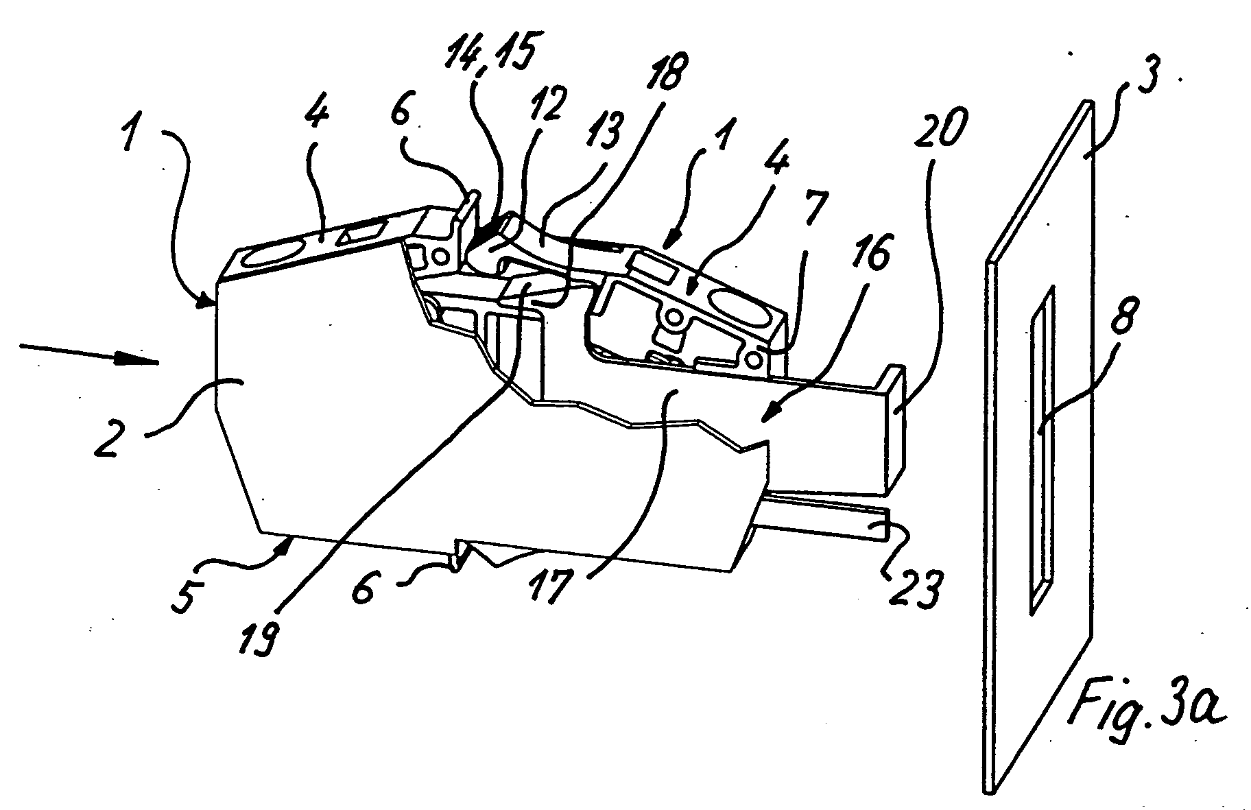
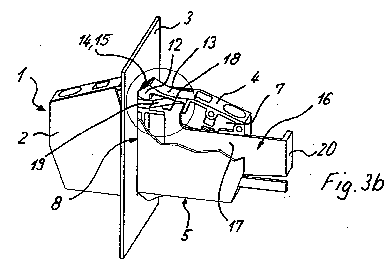
- the fastening means for fixing the feed-through clamp in the wall 3 contain in this feedthrough spring clips 12, which are shown in the Embodiment on the upper and lower narrow side face 4 and 5 of the inner part 7 of the terminal housing 1 arranged in such a way, for example are integrally formed that they by 1 when inserting the terminal housing can be pushed inwards through the opening 8 of the wall 3 (see Figures 4a, 4b) until they spring back after passing through the opening 8 of the wall 3 can and on the corresponding edges of the opening 8 lock the inside of the wall 3, whereby the terminal housing 1 at least provisionally sits firmly in wall 3.
- the spring catches 12 have on their outer sides a run-up slope 13, which push back when passing through the opening 8 cause.
- the spring catches 12 also have catch surfaces 14 on their outer sides, which are provided with a toothing 15.
- the teeth 15 ensure a secure locking with the corresponding edges of the opening 8 on the inside the wall 3.
- the fastener of the feedthrough clamp also include one in the Terminal housing 1 arranged blocking element 16, which is designed to Block spring catches 12 in their catch position so that they are not pushed back can be, whereby a reliable tight fit of the terminal housing 1 is guaranteed in the wall 3.
- the blocking element is a flat slide 17 formed, which carries on its acting clevises 18, each on the outside Have undercarriages 19.
- the blocking element 16 is in the terminal housing 1 captive between a release position and a blocking position slidably arranged.
- the backs of the clevises 18 prevent that the blocking element from the release position even further outwards the terminal housing 1 can be pulled out.
- the blocking element 16 has protruding inside from the inner part 7 of the terminal housing 1 Actuation end 20.
- the spring catches 12 already one cause certain tightness of the terminal housing 1 in the wall are up to Operation of the blocking element and in particular during the operation of the Blocking element on the inside of the wall no simultaneous handling required on the outside of the wall on the outer part 2 of the terminal housing 1.
- the blocking element 16 is in the multiple Terminal housing 1 guided.
- a guide surface is provided in the corresponding position in the terminal housing 1.
- the clevises carry 18 small lateral guide lugs 22.
- the lower region of the flat slide 17 is also designed as a spring catch 23. Its small underside catch 24 latches in the blocking position of the blocking element on the terminal housing and thus secures this blocking position.
- the spring latch 23 Lift unlatched.
Landscapes
- Connector Housings Or Holding Contact Members (AREA)
- Insulated Conductors (AREA)
Abstract
Description
- Figur 1
- eine Durchführungsklemme in einer Phase kurz vor Vollendung der Durchsteckung durch die Wand in sprengbildlicher Darstellung des Blockierelementes und des seitlichen Deckels,
- Figur 2
- eine Seitenansicht der Durchführungsklemme in teilweiser Schnittdarstellung in der Durchsteckphase entsprechend Figur 1,
- Figuren 3a - 3c
- die Durchführungsklemme, teilweise aufgebrochen, in perspektivischer Darstellung in drei verschiedenen Phasen der Montage in der Wand,
- Figuren 4a - 4c
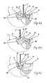
- in Einzelansicht eine Federraste mit angrenzenden Klemmengehäuseteilen und dem Blockierelement in drei verschiedenen Montagephasen.
Claims (9)
- Durchführungsklemme für elektrische Leiter, mit einem Klemmengehäuse (1) aus Isolierstoff, das einen auf einer Außenseite einer Wand (3) mit Anschlägen (6) abstützbaren Außenteil (2) und einen nach Durchstecken des Klemmengehäuses (1) durch eine Öffnung (8) in der Wand (3) auf der Wandinnenseite positionierten Innenteil (7) aufweist und in dem Außenteil (2) mindestens ein Außenleiteranschluß (9) und in dem Innenteil (7) mindestens ein elektrisch mit dem Außenleiteranschluß (9) verbundener Innenleiteranschluß (10) angeordnet sind und ferner gegen die Wandinnenseite wirkende Befestigungsmittel zum Festsetzen des Klemmengehäuses (1) in der Wand (3) vorgesehen sind, dadurch gekennzeichnet, daß an dem Innenteil (7) des Klemmengehäuses (1) Federrasten (12) derart angeordnet sind, daß sie beim Durchstecken des Klemmengehäuses (1) durch die Öffnung (8) in der Wand (3) zurückgedrängt werden und nach ihrem Durchtritt durch die Wand (3) zurückfedern und sich an den entsprechenden innenseitigen Kanten der Öffnung (8) verrasten und in dem Innenteil (7) des Klemmengehäuses (1) ein Blockierelement (16) angeordnet ist, das in dem Innenteil (7) zwischen einer Freigabestellung und einer Blockierstellung verschieblich geführt ist, in der die Federrasten (12) in ihrer Raststellung blockiert sind.
- Durchführungsklemme nach Anspruch 1, dadurch gekennzeichnet, daß die Federrasten (12) jeweils außenseitig Anlaufschrägen (13) für das Zurückdrängen durch die Kanten der Öffnung (8) aufweisen.
- Durchführungsklemme nach Anspruch 1 oder 2, dadurch gekennzeichnet, daß die Federrasten (12) Rastflächen (14) zum Zusammenwirken mit den entsprechenden Kanten der Öffnung (8) in der Raststellung aufweisen.
- Durchführungsklemme nach Anspruch 3, dadurch gekennzeichnet, daß die Rastflächen (14) eine Verzahnung (15) aufweisen.
- Durchführungsklemme nach Anspruch 1, dadurch gekennzeichnet, daß das Blockierelement (16) einen flachen Schieber (17) aufweist, an dessen Wirkende Gabelköpfe (18) zum Unterfahren der Federrasten (12) vorgesehen sind.
- Durchführungsklemme nach Anspruch 5, dadurch gekennzeichnet, daß die Gabelköpfe (18) jeweils außenseitig Unterfahrschrägen (19) aufweisen, in deren Endbereich jeweils eine Blockierzone (21) gebildet ist.
- Durchführungsklemme nach Anspruch 5 oder 6, dadurch gekennzeichnet, daß das Blockierelement (16) über die Hinterseiten der Gabelköpfe (18) und entsprechende Anschlagflächen im Klemmengehäuse (1) in diesem unverlierbar gehalten ist.
- Durchführungsklemme nach Anspruch 5, dadurch gekennzeichnet, daß das Blockierelement (16) an dem flachen Schieber (17) eine Führungszone zur Führung am Klemmengehäuse (1) aufweist und an den Gabelköpfen (18) zusätzliche Führungsansätze (22) vorgesehen sind.
- Durchführungsklemme nach Anspruch 5, dadurch gekennzeichnet, daß das Blockierelement (16) an der Unterseite des flachen Schiebers (17) einen Federrastbügel (23) mit einer Rastnase (24) zum Verrasten am Klemmengehäuse (1) in der Blockierstellung aufweist.
Applications Claiming Priority (2)
| Application Number | Priority Date | Filing Date | Title |
|---|---|---|---|
| DE20200974U | 2002-01-24 | ||
| DE20200974U DE20200974U1 (de) | 2002-01-24 | 2002-01-24 | Durchführungsklemme für elektrische Leiter |
Publications (2)
| Publication Number | Publication Date |
|---|---|
| EP1333544A1 true EP1333544A1 (de) | 2003-08-06 |
| EP1333544B1 EP1333544B1 (de) | 2009-11-04 |
Family
ID=7966876
Family Applications (1)
| Application Number | Title | Priority Date | Filing Date |
|---|---|---|---|
| EP03000237A Expired - Lifetime EP1333544B1 (de) | 2002-01-24 | 2003-01-08 | Durchführungsklemme für elektrische Leiter |
Country Status (3)
| Country | Link |
|---|---|
| EP (1) | EP1333544B1 (de) |
| AT (1) | ATE447781T1 (de) |
| DE (2) | DE20200974U1 (de) |
Cited By (3)
| Publication number | Priority date | Publication date | Assignee | Title |
|---|---|---|---|---|
| WO2004023606A1 (de) * | 2002-09-05 | 2004-03-18 | Schaffner Emv Ag | Durchführungsklemme |
| JP2006522437A (ja) * | 2003-04-04 | 2006-09-28 | フェニックス コンタクト ゲゼルシャフト ミット ベシュレンクテル ハフツング ウント コンパニー コマンディートゲゼルシャフト | くさび形の固定を備えた壁貫通型クリップ/プラグコネクター |
| US20150147909A1 (en) * | 2012-05-14 | 2015-05-28 | Phoenix Contact Gmbh & Co. Kg | Connection terminal |
Families Citing this family (7)
| Publication number | Priority date | Publication date | Assignee | Title |
|---|---|---|---|---|
| EP1655813A1 (de) | 2004-11-09 | 2006-05-10 | Phoenix Contact GmbH & Co. KG | Befestigung für elektrische Verbindung |
| FR2901416B1 (fr) * | 2006-05-22 | 2008-08-08 | Legrand France | Ensemble comportant un bloc de jonction pour conducteurs electriques et une cloison amovible a disposer contre le bloc de jonction |
| DE102008024366B4 (de) * | 2008-05-20 | 2010-11-25 | Phoenix Contact Gmbh & Co. Kg | Durchführungsklemme |
| DE202010010424U1 (de) | 2010-07-20 | 2011-10-25 | Weidmüller Interface GmbH & Co. KG | Wanddurchführungsklemme für elektrische Leiter |
| DE102016111847B4 (de) | 2016-06-28 | 2019-02-14 | Phoenix Contact Gmbh & Co. Kg | Durchführungsklemme |
| LU93126B1 (de) * | 2016-06-28 | 2018-01-24 | Phoenix Contact Gmbh & Co Kg Intellectual Property Licenses & Standards | Durchführungsklemme |
| DE102017124143A1 (de) | 2017-10-17 | 2019-04-18 | Phoenix Contact Gmbh & Co. Kg | Befestigungsklemme |
Citations (3)
| Publication number | Priority date | Publication date | Assignee | Title |
|---|---|---|---|---|
| US5062024A (en) * | 1989-04-01 | 1991-10-29 | Wago Verwaltungsgesellschaft Mbh | Modular connector for printed circuit boards |
| US5613876A (en) * | 1992-05-29 | 1997-03-25 | Sumitomo Wiring Systems, Ltd. | Body-mounted connector |
| DE19801260A1 (de) * | 1998-01-09 | 1999-07-22 | Wago Verwaltungs Gmbh | Wand-Durchführungsklemme für elektr. Leiter |
Family Cites Families (5)
| Publication number | Priority date | Publication date | Assignee | Title |
|---|---|---|---|---|
| DE3445959A1 (de) * | 1984-12-17 | 1986-06-26 | Siemens AG, 1000 Berlin und 8000 München | Anreihbare durchfuehrungsklemme |
| DE3613681C1 (en) * | 1986-04-23 | 1987-06-04 | Phoenix Elekt | Electrical connecting terminal for passing a cable (lead, line) through a housing wall or the like |
| DE3733156C1 (en) * | 1987-10-01 | 1988-11-10 | Phoenix Elekt | Bushing terminal |
| DE9003232U1 (de) * | 1990-03-20 | 1990-07-19 | Adels-Contact Elektrotechnische Fabrik GmbH & Co KG, 51469 Bergisch Gladbach | Durchführungsklemme für Vergußtransformatoren mit einem Zugbügel-Schraubkontakt |
| DE9102953U1 (de) * | 1991-03-13 | 1991-06-06 | Adels-Contact Elektrotechnische Fabrik GmbH & Co KG, 51469 Bergisch Gladbach | Durchführungsklemme für Vergußtransformatoren |
-
2002
- 2002-01-24 DE DE20200974U patent/DE20200974U1/de not_active Expired - Lifetime
-
2003
- 2003-01-08 DE DE50312080T patent/DE50312080D1/de not_active Expired - Lifetime
- 2003-01-08 EP EP03000237A patent/EP1333544B1/de not_active Expired - Lifetime
- 2003-01-08 AT AT03000237T patent/ATE447781T1/de not_active IP Right Cessation
Patent Citations (3)
| Publication number | Priority date | Publication date | Assignee | Title |
|---|---|---|---|---|
| US5062024A (en) * | 1989-04-01 | 1991-10-29 | Wago Verwaltungsgesellschaft Mbh | Modular connector for printed circuit boards |
| US5613876A (en) * | 1992-05-29 | 1997-03-25 | Sumitomo Wiring Systems, Ltd. | Body-mounted connector |
| DE19801260A1 (de) * | 1998-01-09 | 1999-07-22 | Wago Verwaltungs Gmbh | Wand-Durchführungsklemme für elektr. Leiter |
Cited By (6)
| Publication number | Priority date | Publication date | Assignee | Title |
|---|---|---|---|---|
| WO2004023606A1 (de) * | 2002-09-05 | 2004-03-18 | Schaffner Emv Ag | Durchführungsklemme |
| US7090526B2 (en) | 2002-09-05 | 2006-08-15 | Schaffner Emv Ag | Lead-through terminal |
| JP2006522437A (ja) * | 2003-04-04 | 2006-09-28 | フェニックス コンタクト ゲゼルシャフト ミット ベシュレンクテル ハフツング ウント コンパニー コマンディートゲゼルシャフト | くさび形の固定を備えた壁貫通型クリップ/プラグコネクター |
| US7513794B2 (en) | 2003-04-04 | 2009-04-07 | Phoenix Contact Gmbh & Co. Kg | Clamp/plug connector for through-wall connection having wedge-shaped attachment |
| US20150147909A1 (en) * | 2012-05-14 | 2015-05-28 | Phoenix Contact Gmbh & Co. Kg | Connection terminal |
| US9954322B2 (en) * | 2012-05-14 | 2018-04-24 | Phoenix Contact Gmbh & Co. Kg | Connection terminal |
Also Published As
| Publication number | Publication date |
|---|---|
| DE50312080D1 (de) | 2009-12-17 |
| DE20200974U1 (de) | 2003-05-28 |
| ATE447781T1 (de) | 2009-11-15 |
| EP1333544B1 (de) | 2009-11-04 |
Similar Documents
| Publication | Publication Date | Title |
|---|---|---|
| DE3432302C2 (de) | Schelle für elektrische Kabelbündel | |
| DE69607404T2 (de) | Elektrischer Verbinder mit Kontaktverriegelungsteil und verschiebbarem Nocken | |
| EP2881597B1 (de) | Befestigungsvorrichtung für Kabel | |
| EP1333544B1 (de) | Durchführungsklemme für elektrische Leiter | |
| DE102019135726A1 (de) | Halterahmen für einen Steckverbinder | |
| DE3732434A1 (de) | Installationseinbaugeraet | |
| EP0462234B1 (de) | Steckerleiste | |
| DE102009057328A1 (de) | Spann- oder Führungsschiene | |
| DE2500189A1 (de) | Elektrischer verbinder | |
| DE69328466T2 (de) | Verbinder | |
| EP1045098B1 (de) | Stangenverschluss mit Rundstange | |
| DE202010010424U1 (de) | Wanddurchführungsklemme für elektrische Leiter | |
| DE2119060A1 (de) | Steckverbindung | |
| DE69806845T2 (de) | Halbautomatische Verbindung zusammen mit mechanischer Kupplung | |
| DE3015138A1 (de) | Verriegelbarer steckverbinder | |
| EP1722454A2 (de) | Befestigungsvorrichtung für ein Kabel | |
| DE3813948A1 (de) | Isoliergehaeuse fuer eine flachsteckhuelse | |
| DE60027072T2 (de) | Elektrische Steckverbindung, insbesondere für Kraftfahrzeuganwendungen | |
| DE202009014693U1 (de) | Beschlaganordnung | |
| DE2830640A1 (de) | Spielfahrzeug-gleisabschnitt | |
| DE10135662A1 (de) | Gerätebecherrahmen für Unterfluranwendungen | |
| DE8716451U1 (de) | Gehäuseabdeckung | |
| DE20204674U1 (de) | Befestigungsvorrichtung für Geräteeinsätze in Arbeitsplatten | |
| DE202008001687U1 (de) | Haltevorrichtung für eine Vorhangschiene | |
| DE202016004829U1 (de) | Befestigungselement für eine Trennwand und Aufbewahrungselement mit wenigstens einer Trennwand |
Legal Events
| Date | Code | Title | Description |
|---|---|---|---|
| PUAI | Public reference made under article 153(3) epc to a published international application that has entered the european phase |
Free format text: ORIGINAL CODE: 0009012 |
|
| 17P | Request for examination filed |
Effective date: 20030508 |
|
| AK | Designated contracting states |
Designated state(s): AT BE BG CH CY CZ DE DK EE ES FI FR GB GR HU IE IT LI LU MC NL PT SE SI SK TR |
|
| AX | Request for extension of the european patent |
Extension state: AL LT LV MK RO |
|
| AKX | Designation fees paid |
Designated state(s): AT BE BG CH CY CZ DE DK EE ES FI FR GB GR HU IE IT LI LU MC NL PT SE SI SK TR |
|
| GRAP | Despatch of communication of intention to grant a patent |
Free format text: ORIGINAL CODE: EPIDOSNIGR1 |
|
| GRAS | Grant fee paid |
Free format text: ORIGINAL CODE: EPIDOSNIGR3 |
|
| GRAA | (expected) grant |
Free format text: ORIGINAL CODE: 0009210 |
|
| RAP1 | Party data changed (applicant data changed or rights of an application transferred) |
Owner name: WEIDMUELLER INTERFACE GMBH & CO. KG |
|
| AK | Designated contracting states |
Kind code of ref document: B1 Designated state(s): AT BE BG CH CY CZ DE DK EE ES FI FR GB GR HU IE IT LI LU MC NL PT SE SI SK TR |
|
| REG | Reference to a national code |
Ref country code: GB Ref legal event code: FG4D Free format text: NOT ENGLISH |
|
| REG | Reference to a national code |
Ref country code: CH Ref legal event code: EP |
|
| REG | Reference to a national code |
Ref country code: IE Ref legal event code: FG4D |
|
| REF | Corresponds to: |
Ref document number: 50312080 Country of ref document: DE Date of ref document: 20091217 Kind code of ref document: P |
|
| NLV1 | Nl: lapsed or annulled due to failure to fulfill the requirements of art. 29p and 29m of the patents act | ||
| PG25 | Lapsed in a contracting state [announced via postgrant information from national office to epo] |
Ref country code: SE Free format text: LAPSE BECAUSE OF FAILURE TO SUBMIT A TRANSLATION OF THE DESCRIPTION OR TO PAY THE FEE WITHIN THE PRESCRIBED TIME-LIMIT Effective date: 20091104 Ref country code: PT Free format text: LAPSE BECAUSE OF FAILURE TO SUBMIT A TRANSLATION OF THE DESCRIPTION OR TO PAY THE FEE WITHIN THE PRESCRIBED TIME-LIMIT Effective date: 20100304 Ref country code: FI Free format text: LAPSE BECAUSE OF FAILURE TO SUBMIT A TRANSLATION OF THE DESCRIPTION OR TO PAY THE FEE WITHIN THE PRESCRIBED TIME-LIMIT Effective date: 20091104 Ref country code: ES Free format text: LAPSE BECAUSE OF FAILURE TO SUBMIT A TRANSLATION OF THE DESCRIPTION OR TO PAY THE FEE WITHIN THE PRESCRIBED TIME-LIMIT Effective date: 20100215 |
|
| REG | Reference to a national code |
Ref country code: IE Ref legal event code: FD4D |
|
| PG25 | Lapsed in a contracting state [announced via postgrant information from national office to epo] |
Ref country code: SI Free format text: LAPSE BECAUSE OF FAILURE TO SUBMIT A TRANSLATION OF THE DESCRIPTION OR TO PAY THE FEE WITHIN THE PRESCRIBED TIME-LIMIT Effective date: 20091104 Ref country code: CY Free format text: LAPSE BECAUSE OF FAILURE TO SUBMIT A TRANSLATION OF THE DESCRIPTION OR TO PAY THE FEE WITHIN THE PRESCRIBED TIME-LIMIT Effective date: 20091104 |
|
| PG25 | Lapsed in a contracting state [announced via postgrant information from national office to epo] |
Ref country code: IE Free format text: LAPSE BECAUSE OF FAILURE TO SUBMIT A TRANSLATION OF THE DESCRIPTION OR TO PAY THE FEE WITHIN THE PRESCRIBED TIME-LIMIT Effective date: 20091104 Ref country code: EE Free format text: LAPSE BECAUSE OF FAILURE TO SUBMIT A TRANSLATION OF THE DESCRIPTION OR TO PAY THE FEE WITHIN THE PRESCRIBED TIME-LIMIT Effective date: 20091104 Ref country code: DK Free format text: LAPSE BECAUSE OF FAILURE TO SUBMIT A TRANSLATION OF THE DESCRIPTION OR TO PAY THE FEE WITHIN THE PRESCRIBED TIME-LIMIT Effective date: 20091104 Ref country code: BG Free format text: LAPSE BECAUSE OF FAILURE TO SUBMIT A TRANSLATION OF THE DESCRIPTION OR TO PAY THE FEE WITHIN THE PRESCRIBED TIME-LIMIT Effective date: 20100204 |
|
| BERE | Be: lapsed |
Owner name: WEIDMULLER INTERFACE G.M.B.H. & CO. KG Effective date: 20100131 |
|
| PG25 | Lapsed in a contracting state [announced via postgrant information from national office to epo] |
Ref country code: SK Free format text: LAPSE BECAUSE OF FAILURE TO SUBMIT A TRANSLATION OF THE DESCRIPTION OR TO PAY THE FEE WITHIN THE PRESCRIBED TIME-LIMIT Effective date: 20091104 Ref country code: MC Free format text: LAPSE BECAUSE OF NON-PAYMENT OF DUE FEES Effective date: 20100131 Ref country code: CZ Free format text: LAPSE BECAUSE OF FAILURE TO SUBMIT A TRANSLATION OF THE DESCRIPTION OR TO PAY THE FEE WITHIN THE PRESCRIBED TIME-LIMIT Effective date: 20091104 |
|
| REG | Reference to a national code |
Ref country code: CH Ref legal event code: PL |
|
| PLBE | No opposition filed within time limit |
Free format text: ORIGINAL CODE: 0009261 |
|
| STAA | Information on the status of an ep patent application or granted ep patent |
Free format text: STATUS: NO OPPOSITION FILED WITHIN TIME LIMIT |
|
| 26N | No opposition filed |
Effective date: 20100805 |
|
| REG | Reference to a national code |
Ref country code: FR Ref legal event code: ST Effective date: 20100930 |
|
| GBPC | Gb: european patent ceased through non-payment of renewal fee |
Effective date: 20100204 |
|
| PG25 | Lapsed in a contracting state [announced via postgrant information from national office to epo] |
Ref country code: LI Free format text: LAPSE BECAUSE OF NON-PAYMENT OF DUE FEES Effective date: 20100131 Ref country code: GR Free format text: LAPSE BECAUSE OF FAILURE TO SUBMIT A TRANSLATION OF THE DESCRIPTION OR TO PAY THE FEE WITHIN THE PRESCRIBED TIME-LIMIT Effective date: 20100205 Ref country code: FR Free format text: LAPSE BECAUSE OF NON-PAYMENT OF DUE FEES Effective date: 20100201 Ref country code: CH Free format text: LAPSE BECAUSE OF NON-PAYMENT OF DUE FEES Effective date: 20100131 |
|
| PG25 | Lapsed in a contracting state [announced via postgrant information from national office to epo] |
Ref country code: BE Free format text: LAPSE BECAUSE OF NON-PAYMENT OF DUE FEES Effective date: 20100131 |
|
| PG25 | Lapsed in a contracting state [announced via postgrant information from national office to epo] |
Ref country code: GB Free format text: LAPSE BECAUSE OF NON-PAYMENT OF DUE FEES Effective date: 20100204 Ref country code: IT Free format text: LAPSE BECAUSE OF FAILURE TO SUBMIT A TRANSLATION OF THE DESCRIPTION OR TO PAY THE FEE WITHIN THE PRESCRIBED TIME-LIMIT Effective date: 20091104 |
|
| PG25 | Lapsed in a contracting state [announced via postgrant information from national office to epo] |
Ref country code: AT Free format text: LAPSE BECAUSE OF NON-PAYMENT OF DUE FEES Effective date: 20100108 |
|
| PG25 | Lapsed in a contracting state [announced via postgrant information from national office to epo] |
Ref country code: LU Free format text: LAPSE BECAUSE OF NON-PAYMENT OF DUE FEES Effective date: 20100108 Ref country code: NL Free format text: LAPSE BECAUSE OF FAILURE TO SUBMIT A TRANSLATION OF THE DESCRIPTION OR TO PAY THE FEE WITHIN THE PRESCRIBED TIME-LIMIT Effective date: 20091104 Ref country code: HU Free format text: LAPSE BECAUSE OF FAILURE TO SUBMIT A TRANSLATION OF THE DESCRIPTION OR TO PAY THE FEE WITHIN THE PRESCRIBED TIME-LIMIT Effective date: 20100505 |
|
| PG25 | Lapsed in a contracting state [announced via postgrant information from national office to epo] |
Ref country code: TR Free format text: LAPSE BECAUSE OF FAILURE TO SUBMIT A TRANSLATION OF THE DESCRIPTION OR TO PAY THE FEE WITHIN THE PRESCRIBED TIME-LIMIT Effective date: 20091104 |
|
| PGFP | Annual fee paid to national office [announced via postgrant information from national office to epo] |
Ref country code: DE Payment date: 20200121 Year of fee payment: 18 |
|
| REG | Reference to a national code |
Ref country code: DE Ref legal event code: R119 Ref document number: 50312080 Country of ref document: DE |
|
| PG25 | Lapsed in a contracting state [announced via postgrant information from national office to epo] |
Ref country code: DE Free format text: LAPSE BECAUSE OF NON-PAYMENT OF DUE FEES Effective date: 20210803 |