EP1333212A2 - Fuel hose - Google Patents
Fuel hose Download PDFInfo
- Publication number
- EP1333212A2 EP1333212A2 EP03001538A EP03001538A EP1333212A2 EP 1333212 A2 EP1333212 A2 EP 1333212A2 EP 03001538 A EP03001538 A EP 03001538A EP 03001538 A EP03001538 A EP 03001538A EP 1333212 A2 EP1333212 A2 EP 1333212A2
- Authority
- EP
- European Patent Office
- Prior art keywords
- different
- same
- fuel hose
- dimer acid
- layer
- Prior art date
- Legal status (The legal status is an assumption and is not a legal conclusion. Google has not performed a legal analysis and makes no representation as to the accuracy of the status listed.)
- Granted
Links
Images

Classifications
-
- F—MECHANICAL ENGINEERING; LIGHTING; HEATING; WEAPONS; BLASTING
- F16—ENGINEERING ELEMENTS AND UNITS; GENERAL MEASURES FOR PRODUCING AND MAINTAINING EFFECTIVE FUNCTIONING OF MACHINES OR INSTALLATIONS; THERMAL INSULATION IN GENERAL
- F16L—PIPES; JOINTS OR FITTINGS FOR PIPES; SUPPORTS FOR PIPES, CABLES OR PROTECTIVE TUBING; MEANS FOR THERMAL INSULATION IN GENERAL
- F16L11/00—Hoses, i.e. flexible pipes
- F16L11/04—Hoses, i.e. flexible pipes made of rubber or flexible plastics
- F16L11/12—Hoses, i.e. flexible pipes made of rubber or flexible plastics with arrangements for particular purposes, e.g. specially profiled, with protecting layer, heated, electrically conducting
- F16L11/127—Hoses, i.e. flexible pipes made of rubber or flexible plastics with arrangements for particular purposes, e.g. specially profiled, with protecting layer, heated, electrically conducting electrically conducting
-
- F—MECHANICAL ENGINEERING; LIGHTING; HEATING; WEAPONS; BLASTING
- F16—ENGINEERING ELEMENTS AND UNITS; GENERAL MEASURES FOR PRODUCING AND MAINTAINING EFFECTIVE FUNCTIONING OF MACHINES OR INSTALLATIONS; THERMAL INSULATION IN GENERAL
- F16L—PIPES; JOINTS OR FITTINGS FOR PIPES; SUPPORTS FOR PIPES, CABLES OR PROTECTIVE TUBING; MEANS FOR THERMAL INSULATION IN GENERAL
- F16L11/00—Hoses, i.e. flexible pipes
- F16L11/04—Hoses, i.e. flexible pipes made of rubber or flexible plastics
-
- F—MECHANICAL ENGINEERING; LIGHTING; HEATING; WEAPONS; BLASTING
- F16—ENGINEERING ELEMENTS AND UNITS; GENERAL MEASURES FOR PRODUCING AND MAINTAINING EFFECTIVE FUNCTIONING OF MACHINES OR INSTALLATIONS; THERMAL INSULATION IN GENERAL
- F16L—PIPES; JOINTS OR FITTINGS FOR PIPES; SUPPORTS FOR PIPES, CABLES OR PROTECTIVE TUBING; MEANS FOR THERMAL INSULATION IN GENERAL
- F16L11/00—Hoses, i.e. flexible pipes
- F16L11/04—Hoses, i.e. flexible pipes made of rubber or flexible plastics
- F16L2011/047—Hoses, i.e. flexible pipes made of rubber or flexible plastics with a diffusion barrier layer
-
- Y—GENERAL TAGGING OF NEW TECHNOLOGICAL DEVELOPMENTS; GENERAL TAGGING OF CROSS-SECTIONAL TECHNOLOGIES SPANNING OVER SEVERAL SECTIONS OF THE IPC; TECHNICAL SUBJECTS COVERED BY FORMER USPC CROSS-REFERENCE ART COLLECTIONS [XRACs] AND DIGESTS
- Y10—TECHNICAL SUBJECTS COVERED BY FORMER USPC
- Y10S—TECHNICAL SUBJECTS COVERED BY FORMER USPC CROSS-REFERENCE ART COLLECTIONS [XRACs] AND DIGESTS
- Y10S138/00—Pipes and tubular conduits
- Y10S138/07—Resins
-
- Y—GENERAL TAGGING OF NEW TECHNOLOGICAL DEVELOPMENTS; GENERAL TAGGING OF CROSS-SECTIONAL TECHNOLOGIES SPANNING OVER SEVERAL SECTIONS OF THE IPC; TECHNICAL SUBJECTS COVERED BY FORMER USPC CROSS-REFERENCE ART COLLECTIONS [XRACs] AND DIGESTS
- Y10—TECHNICAL SUBJECTS COVERED BY FORMER USPC
- Y10T—TECHNICAL SUBJECTS COVERED BY FORMER US CLASSIFICATION
- Y10T428/00—Stock material or miscellaneous articles
- Y10T428/13—Hollow or container type article [e.g., tube, vase, etc.]
- Y10T428/1352—Polymer or resin containing [i.e., natural or synthetic]
- Y10T428/139—Open-ended, self-supporting conduit, cylinder, or tube-type article
Definitions
- the present invention relates to a fuel hose for use as a fuel transportation pipe for transporting an automotive fuel such as a gasoline, an alcohol-containing gasoline (gasohol), an alcohol, hydrogen, liquified petroleum gas (LPG), compressed natural gas (CNG), light oil or dimethyl ether.
- an automotive fuel such as a gasoline, an alcohol-containing gasoline (gasohol), an alcohol, hydrogen, liquified petroleum gas (LPG), compressed natural gas (CNG), light oil or dimethyl ether.
- low-permeability fuel hoses hitherto proposed are those produced by employing polyester resins such as polybutylene naphthalate (PBN) and polybutylene terephthalate (PBT) which are less permeable to fuels.
- PBN polybutylene naphthalate
- PBT polybutylene terephthalate
- a hose of a single layer structure is produced by employing such a polyester resin alone, the hose has poor flexibility because the polyester resin (PBN, PBT etc.) is highly rigid. Therefore, it is a common practice to laminate a thin polyester resin layer and a thermoplastic resin layer for production of a low-permeability fuel hose.
- a polyester resin (PBN, PBT etc.) does not adhere well to other types of materials. Therefore, in the above hose, the polyester resin layer and the thermoplastic resin layer should be laminated by providing an adhesive layer therebetween, correspondingly complicating the production process.
- a hose has been proposed which includes an innermost layer of a thermoplastic polyester elastomer provided on the inner periphery of a polyester resin layer such as of the PBN or the PBT.
- the innermost layer and the polyester resin layer provided on the outer periphery of the innermost layer are both polyester-based, the innermost layer and the polyester resin layer can be laminated without the use of an adhesive by co-extruding the thermoplastic polyester elastomer and the polyester resin (e.g., PBN).
- the inventors of the present invention found, as a result of further studies on this hose, that the innermost layer of the thermoplastic polyester elastomer is unsatisfactory in sour gasoline resistance (resistance to a sour gasoline generated through oxidation of a gasoline) which is an important property required in hose applications for fuels.
- a fuel hose which comprises at least one layer including an innermost layer comprising a thermoplastic polybutylene terephthalate elastomer containing a dimer acid moiety.
- the inventors of the present invention conducted studies to determine the reason a hose which has an innermost layer composed of the thermoplastic polyester elastomer tends to be inferior in sour gasoline resistance, and discovered that a polyether contained as a soft segment in the thermoplastic polyester elastomer is liable to be eroded by a peroxide in the sour gasoline, thereby resulting in the deterioration of the hose.
- the inventors found that, where a dimer acid moiety is introduced into a thermoplastic polybutylene terephthalate (PBT) elastomer containing polybutylene terephthalate (PBT) as a hard segment to reduce the proportion of the soft segment (polyether) or to entirely replace the soft segment with the dimer acid moiety, the innermost layer is less likely to be eroded by the peroxide in the sour gasoline, whereby the hose tends to be free from deterioration by having an improved sour gasoline resistance.
- PBT thermoplastic polybutylene terephthalate
- PBT polybutylene terephthalate
- the sole figure of the drawing is a diagram illustrating the construction of an exemplary fuel hose according to the present invention.
- a fuel hose according to the present invention includes an inner layer 1, a barrier layer 2 provided on the outer periphery of the inner layer 1, and an outer layer 3 provided on the outer periphery of the barrier layer 2.
- the inner layer 1 comprises a thermoplastic polybutylene terephthalate elastomer containing a moiety of a dimer acid.
- thermoplastic polybutylene terephthalate elastomer containing the dimer acid moiety is employed as a material for the inner layer 1.
- the dimer acid is a dimer obtained through a reaction of two molecules of an organic acid.
- Examples of the dimer acid include aliphatic dimer acids, alicyclic dimer acids and aromatic dimer acids, which may be used either alone or in combination.
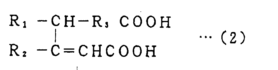
- Examples of aliphatic dimer acids include dimer acids represented by the following general formulae (1) and (2), which may be used either alone or in combination. wherein R 1 and R 2 , which may be the same or different, are alkyl groups; R 3 and R 4 , which may be the same or different, are alkylene groups; and a total carbon number of R 1 to R 4 is preferably 24 to 36. wherein R 1 and R 2 , which may be the same or different, are alkyl groups; R 3 is an alkylene group; and a total carbon number of R 1 to R 3 is preferably 24 to 36.
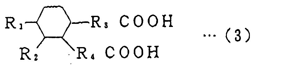
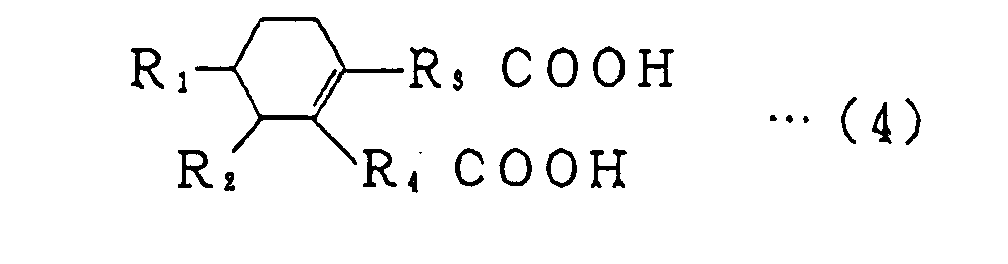
- Examples of alicyclic dimer acids include dimer acids represented by the following general formulae (3) to (6), which may be used either alone or in combination.
- R 1 and R 2 which may be the same or different, are alkyl groups
- R 3 and R 4 which may be the same or different, are alkylene groups
- a total carbon number of R 1 to R 4 is preferably 24 to 36.
- R 1 and R 2 which may be the same or different, are alkyl groups
- R 3 and R 4 which may be the same or different, are alkylene groups
- a total carbon number of R 1 to R 4 is preferably 24 to 36.
- R 1 and R 2 which may be the same or different, are alkyl groups; R 3 and R 4 , which may be the same or different, are alkylene groups; and a total carbon number of R 1 to R 4 is preferably 24 to 36.
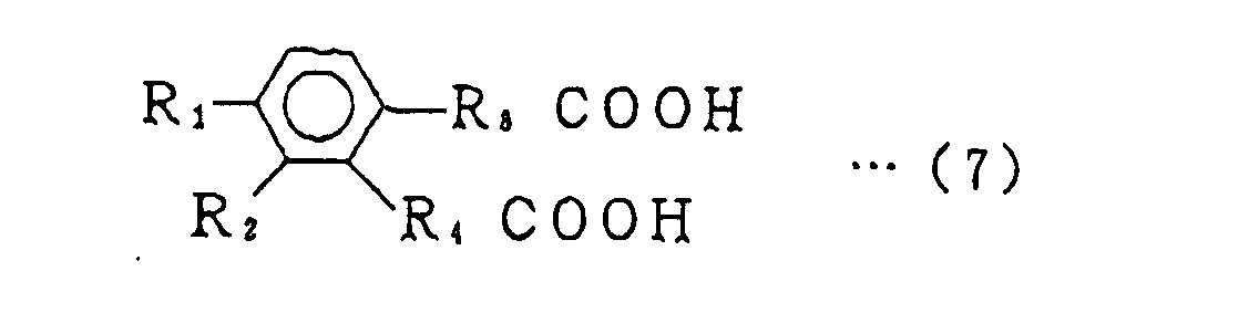
- aromatic dimer acids include dimer acids represented by the following general formula (7). wherein R 1 and R 2 , which may be the same or different, are alkyl groups; R 3 and R 4 , which may be the same or different, are alkylene groups; and a total carbon number of R 1 to R 4 is preferably 24 to 36.
- dimer acids include acids sold under the trade name PRIPOL 1008 by Uniqema of Gouda, the Netherlands (a hydrogenated dimer acid product containing an aromatic dimer acid, an alicyclic dimer acid and an aliphatic dimer acid in a molar ratio of 9:54:37 (carbon number: 36)), Uniqema's PRIPOL 1009 (a hydrogenated dimer acid product containing an aromatic dimer acid, an alicyclic dimer acid and an aliphatic dimer acid in a molar ratio of 13:64:23 (carbon number: 36)), Uniqema's PRIPOL 1098 (an unhydrogenated dimer acid product containing an aromatic dimer acid, an alicyclic dimer acid and an aliphatic dimer acid in a molar ratio of 13:64:23 (carbon number: 36)), Uniqema's PRIPLASTA 3008 (a dimethyl ester product of PRIPOL 1008), and Uniqema's PRIPLASTA 30
- the PBT-TPE containing the dimer acid moiety may be prepared, for example, by partly substituting terephthalic acid (TPA: a material for the PBT) with the dimer acid.
- TPA terephthalic acid
- a polyether or a polyester as a soft segment may be copolymerized with the dimer acid.
- the proportion of the soft segment in the PBT-TPE containing the dimer acid moiety is preferably not greater than 20 wt% from the viewpoint of sour gasoline resistance.
- polyether to be copolymerized with the dimer acid is polytetramethylene glycol (PTMG).
- polyester to be copolymerized with the dimer acid include polybutylene adipate (PBA) and poly- ⁇ -caprolactone.
- the proportion of the dimer acid moiety in the PBT-TPE containing the dimer acid is preferably 1 mol% to 12 mol%, particularly preferably 1.5 mol% to 11 mol%. If the proportion of the dimer acid moiety is smaller than 1 mol%, flexibility tends to be deteriorated. If the proportion of the dimer acid moiety is greater than 12 mol%, the crystallinity of the PBT tends to be reduced, resulting in reduction of gasoline resistance and mechanical strength.
- the PBT-TPE containing the dimer acid moiety preferably has a flexural modulus of 200 MPa to 2000 MPa, particularly preferably 300 MPa to 2000 MPa.
- the innermost layer material may further contain an electrically conductive material such as carbon black, carbon nano-tubes or metal powder.
- the material tends to dissipate static electricity generated by a fuel pump out of the hose to help prevent accidents such as ignition of a fuel (gasoline) which may otherwise occur due to the static electricity.
- a material for the barrier layer 2 provided on the outer periphery of the inner layer 1 is not particularly limited, but a polyester resin is preferably used as the barrier layer material.
- the polyester resin include a polybutylene naphthalate (PBN) resin, a polybutylene terephthalate (PBT) resin, a polyethylene naphthalate (PEN) resin and a polyethylene terephthalate (PET) resin.
- PBN polybutylene naphthalate
- PBT polybutylene terephthalate
- PEN polyethylene naphthalate
- PET polyethylene terephthalate
- an elastomer blend containing any of these polyester resins as a matrix may be employed as the barrier layer material.
- the PBT resin may be prepared by a DMT method employing dimethyl terephthalate (DMT) and 1,4-butanediol as starting materials, or by a direct polymerization method employing terephthalic acid (TPA) and 1,4-butanediol as starting materials.
- DMT dimethyl terephthalate
- TPA terephthalic acid
- the PBN resin may be prepared by an ester exchange method employing 2,6-dimethyl naphthalate (DMN) and 1,4-butanediol as starting materials, or by a direct polymerization method employing 2,6-naphthalene dicarboxylic acid and 1,4-butanediol as starting materials.
- DBN 2,6-dimethyl naphthalate
- 1,4-butanediol 1,4-butanediol
- the PEN resin may be prepared by an ester exchange method employing 2,6-dimethyl naphthalate (DMN) and ethylene glycol as starting materials, or by a direct polymerization method employing 2,6-naphthalene dicarboxylic acid and ethylene glycol as starting ' materials.
- DNN 2,6-dimethyl naphthalate
- ethylene glycol ethylene glycol
- the PET resin may be prepared by a DMT method employing dimethyl terephthalate (DMT) and ethylene glycol as starting materials, or by a direct polymerization method employing terephthalic acid (TPA) and ethylene glycol as starting materials.
- DMT dimethyl terephthalate
- TPA terephthalic acid
- the barrier layer material may further contain an electrically conductive material such as carbon black, carbon nano-tubes or metal powder so as to have electrical conductivity.
- a material for the outer layer 3 provided on the outer periphery of the barrier layer 2 is not particularly limited, but a thermoplastic polyester elastomer is preferably used as the outer layer material.
- a thermoplastic polyester elastomer include a thermoplastic polybutylene naphthalate elastomer (PBN-TPE) and a thermoplastic polybutylene terephthalate elastomer (PBT-TPE).
- the outer layer material may further contain an electrically conductive material such as carbon black, carbon nano-tubes or metal powder so as to have electrical conductivity.
- the inventive fuel hose is produced, for example, in the following manner.
- the inner layer material essentially containing the PBT-TPE containing the dimer acid moiety, the barrier layer material of the polyester resin (e.g., polybutylene naphthalate (PBN)) and the outer layer material of the thermoplastic polyester elastomer (e.g., thermoplastic PBT elastomer) are prepared.
- the respective layer materials are co-extruded by means of an extruder capable of simultaneous formation of the three layers, are in turn sized by a vacuum sizing method, and then cooled to solidification in a cooling water bath.
- the intended fuel hose (see the Figure) is produced.
- the inventive fuel hose may partially have a bellows structure which is formed by means of a corrugator.
- the production method is not limited thereto.
- the inner layer material may first be extruded around a mandrel for formation of the inner layer 1.
- the barrier layer material and the outer layer material may successively be extruded around the inner layer 1 for formation of the barrier layer 2 and the outer layer 3.
- the inner layer 1 of the inventive fuel hose thus produced typically has a thickness of 0.01 mm to 0.5 mm, preferably 0.1 mm to 0.4 mm.
- the barrier layer 2 typically has a thickness of 0.01 mm to 0.5 mm, preferably 0.05 mm to 0.4 mm.
- the outer layer 3 typically has a thickness of 0.1 mm to 3 mm, preferably 0.3 mm to 1 mm.
- the inventive fuel hose typically has an inner diameter of 3 mm to 60 mm, preferably 4 mm to 30 mm.
- the structure of the inventive fuel hose is not limited to the three-layer structure shown in the Figure, as long as the innermost layer is composed of the aforesaid PBT-TPE containing the dimer acid moiety.
- the fuel hose may be of a single layer structure, a two-layer structure, or a multi-layer structure having four or more layers.
- a single layer structure means that the single layer is the innermost layer.
- the inventive fuel hose may be, preferably, of a five layer structure having a first intermediate layer provided on the inner periphery of the barrier layer 2 and a second intermediate layer provided on the outer periphery of the barrier layer 2 (i.e., inner layer 1/first intermediate layer/barrier layer 2/second intermediate layer/outer layer 3).
- An exemplary material for the first and second intermediate layers is a blend of a PBT and a polyolefin elastomer.
- the blend of the PBT and the polyolefin elastomer is advantageous, because the blend has excellent low-temperature impact resistance and adhesiveness to the barrier layer, and is less expensive than PBN.
- inventive fuel hose is advantageously employed as an automotive fuel hose.
- inventive fuel hose may be employed as a fuel hose for a tractor or a farm tractor.
- PBTS01562 (containing Uniqema's PRIPOL 1008 as a dimer acid moiety in a proportion of 6 mol% and having a flexural modulus of 650 MPa) available from Kanebo Gohsen, Ltd. of Osaka, Japan.
- TQB-OT (having a flexural modulus of 2100 MPa) available from Teijin Chemicals, Ltd. of Tokyo, Japan.
- CELANEX 2001 (having a flexural modulus of 2450 MPa) available from Polyplastics Co., Ltd. of Tokyo, Japan.
- TEONEX TN8770 (having a flexural modulus of 2300 MPa) available from Teijin Chemicals, Ltd. of Tokyo, Japan.
- PERPRENE EN5030 (having a flexural modulus of 470 MPa) available from Toyobo Co., Ltd. of Osaka, Japan.
- HYTREL 7277R07 (having a flexural modulus of 570 MPa) available from E.I. DuPont de Nemours & Company of Wilmington, USA.
- HYTREL 5577R07 (having a flexural modulus of 200 MPa) available from DuPont-Toray Co., Ltd. of Tokyo, Japan.
- An inner layer material, a barrier layer material and an outer layer material as shown in Tables 1 and 2 were prepared for each of fuel hoses of Examples 1 to 6 and Comparative examples 1 and 2.
- the inner layer material, the barrier layer material and the outer layer material were co-extruded by an extruder capable of simultaneous formation of three layers, which were in turn cooled to solidification in a cooling water bath.
- a fuel hose was produced, which had a 0.2 mm thick inner layer, a 0.1 mm thick barrier layer provided on the outer periphery of the inner layer and a 0.7 mm thick outer layer provided on the outer periphery of the barrier layer, and had an inner diameter of 6 mm and an outer diameter of 8 mm.
- An inner layer material, a first intermediate layer material, a barrier layer material, a second intermediate layer material and an outer layer material as shown in Table 2 were prepared for each of fuel hoses of Examples 7 and 8.
- the inner layer material, the first intermediate layer material, the barrier layer material, the second intermediate layer material and the outer layer material were co-extruded by an extruder capable of simultaneous formation of five layers, which were in turn cooled to solidification in a cooling water bath.
- a fuel hose was produced, which had a 0.05 mm thick inner layer, a 0.2 mm thick first intermediate layer, 0.1 mm thick barrier layer, 0.2 mm thick second intermediate layer and a 0.45 mm thick outer layer sequentially stacked in this order, and had an inner diameter of 6 mm and an outer diameter of 8 mm.
- Opposite end portions of a 10 m long fuel hose were each expanded to an inner diameter of 10 mm by means of a cone-shaped jig.
- two metal pipes were prepared which each had an outer diameter of 8 mm with two bulged portions each having an outer diameter of 10 mm and with each one end thereof having a rounded outer periphery.
- These metal pipes were respectively press-fitted into opposite end portions of the hose.
- a blind cap was threadingly attached to one of the metal pipes, and a metal valve was attached to the other metal pipe. Thereafter, regular gasoline (containing 10 vol% ethanol) was supplied into the fuel hose through the metal valve, and the fuel hose was sealed.
- the fuel hose was allowed to stand at 40°C for 3000 hours (the regular gasoline was changed every week). Then, fuel permeation was measured for three days on the basis of a Diurnal Breathing Loss (DBL) pattern by the Sealed Housing for Evaporative Detection (SHED) method in accordance with California Air Resources Board (CARB). Then, fuel permeation per meter of the hose was determined on a day when the maximum fuel permeation was detected.
- DBL Diurnal Breathing Loss
- SHED Sealed Housing for Evaporative Detection
- CARB California Air Resources Board
- a model of degraded gasoline was prepared by blending 5 wt% of lauroyl peroxide (LPO) in Fuel C (50% by volume of toluene + 50% by volume of isoctane). Then, two metal pipes were respectively press-fitted into opposite end portions of a 10 m long fuel hose. After the model of degraded gasoline was circulated through the fuel hose at 60 °C at a pressure of 0.3 MPa for eight hours via a pressure regulator, the model of degraded gasoline was filled in the fuel hose for 16 hours. After this cycle was repeated 30 times, a part of the fuel hose was sampled and bent by 180 degrees. The sampled part was visually observed for the evaluation of the sour gasoline resistance. In Tables 1 and 2, a symbol ⁇ indicates that the fuel hose suffered from no abnormality, and a symbol X indicates that the fuel hose was flattened.
- LPO lauroyl peroxide
- the fuel hoses of the examples were excellent in sour gasoline resistance, and each have a low gasoline permeability.
- the thickness of the barrier layer should be increased. With the barrier layer having an increased thickness, the fuel hoses would be more costly and more rigid because the PBN is costly and highly rigid.
- the intermediate layers composed of the blend of the PBT and the polyolefin elastomer were provided on the inner and outer peripheries of the barrier layer, so that the pressure resistance thereof was improved without increasing the thickness of the barrier layer.
- the blend of the PBT and the polyolefin elastomer is advantageous because it has excellent low-temperature impact resistance and adhesiveness to the barrier layer and is less costly than the PBN.
- the fuel hoses of Comparative Examples 1 and 2 were inferior in sour gasoline resistance though each have a lower gasoline permeability. This is because the inner layer was not composed of the PBT-TPE containing the dimer acid moiety, but composed of PBN-TPE or PBT-TPE. Therefore, it is supposed that the soft segment in the TPE was eroded by a peroxide in the sour gasoline, resulting in the deterioration of the sour gasoline resistance.
- the inventive fuel hose has the innermost layer comprising a thermoplastic PBT elastomer containing a dimer acid moiety. Since the dimer acid moiety is introduced into the thermoplastic PBT elastomer to reduce the proportion of the soft segment (e.g., the polyether) or to entirely replace the soft segment with the dimer acid moiety, the soft segment is made less liable to be eroded by peroxide in the sour gasoline, whereby the sour gasoline resistance of the hose is effectively improved.
- the soft segment e.g., the polyether
- the fuel hose further comprises a barrier layer of polyester resin provided around the innermost layer and an outer layer of thermoplastic polyester elastomer provided around the barrier layer, the fuel hose is made less permeable to automotive fuel and the like.
- the fuel hose is made further less permeable to automotive fuel and the like.
Landscapes
- Engineering & Computer Science (AREA)
- General Engineering & Computer Science (AREA)
- Mechanical Engineering (AREA)
- Rigid Pipes And Flexible Pipes (AREA)
- Laminated Bodies (AREA)
Abstract
Description
correspondingly complicating the production process. To this end, a hose has been proposed which includes an innermost layer of a thermoplastic polyester elastomer provided on the inner periphery of a polyester resin layer such as of the PBN or the PBT. Since the innermost layer and the polyester resin layer provided on the outer periphery of the innermost layer are both polyester-based, the innermost layer and the polyester resin layer can be laminated without the use of an adhesive by co-extruding the thermoplastic polyester elastomer and the polyester resin (e.g., PBN). However, the inventors of the present invention found, as a result of further studies on this hose, that the innermost layer of the thermoplastic polyester elastomer is unsatisfactory in sour gasoline resistance (resistance to a sour gasoline generated through oxidation of a gasoline) which is an important property required in hose applications for fuels.





Claims (9)
- A fuel hose comprising at least one layer including an innermost layer which comprises a thermoplastic polybutylene terephthalate elastomer containing a dimer acid moiety.
- A fuel hose as set forth in claim 1, further including a barrier layer comprising a polyester resin and provided around the innermost layer, and an outer layer comprising a thermoplastic polyester elastomer and provided around the barrier layer.
- A fuel hose as set forth in claim 2, wherein the thermoplastic polyester elastomer for the outer layer is at least one of a thermoplastic polybutylene naphthalate elastomer and a thermoplastic polybutylene terephthalate elastomer.
- A fuel hose as set forth in any one of claim 1 to claim 3, wherein the innermost layer further comprises an electrically conductive material.
- A fuel hose as set forth in any one of the preceding Claims wherein the dimer acid is an aliphatic dimer acid, an alicyclic dimer acid and/or an aromatic dimer acid, alone or in combination.
- A fuel hose as set forth in Claim 5 wherein the aliphatic dimer acid is selected from dimer acids represented by the following general formulae (1) or (2), which may be used either alone or in combination:wherein R1 and R2, which may be the same or different, are alkyl groups; R3 and R4, which may be the same or different, are alkylene groups; and a total carbon number of R1 to R4 is preferably 24 to 36;
 wherein R1 and R2, which may be the same or different are, alkyl groups; R3 is an alkylene group; and a total carbon number of R1 to R3 is preferably 24 to 36.
- A fuel hose as set forth in Claim 5 wherein the alicyclic dimer acid is selected from dimer acids represented by the following general formulae (3) to (6), which may be used either alone or in combination:wherein R1 and R2, which may be the same or different, are alkyl groups; R3 and R4, which may be the same or different, are alkylene groups; and total carbon number of R1 to R4 is preferably 24 to 36;
 wherein R1 and R2, which may be the same or different, are alkyl groups; R3 and R4, which may be the same or different, are alkylene groups; and a total carbon number of R1 to R4 is preferably 24 to 36;
 wherein R1 and R2, which may be the same or different, are alkyl groups; R3 and R4, which may be the same or different, are alkylene groups; and a total carbon number of R1 to R4 is preferably 24 to 36;
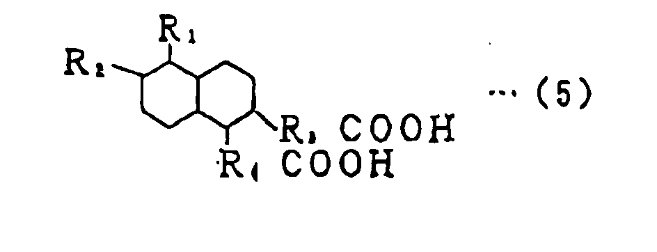 wherein R1 and R2, which may be the same or different, are allyl groups; R3 and R4, which may be the same or different, are alkylene groups; and a total carbon number of R1 to R4 is preferably 24 to 36.
- A hose as set forth in Claim 5 wherein the aromatic dimer acids are dimer acids represented by the following general formula (7).wherein R1 and R2, which may be the same or different, are allyl groups; R3 and R4, which may be the same or different, are alkylene groups; and a total carbon number of R1 to R4 is preferably 24 to 36.

- A fuel hose as set forth in Claim 2 wherein the barrier layer and all the outer layer further contain an electrically conductive material.
Applications Claiming Priority (4)
| Application Number | Priority Date | Filing Date | Title |
|---|---|---|---|
| JP2002016178 | 2002-01-24 | ||
| JP2002016178 | 2002-01-24 | ||
| JP2002277444A JP2003287165A (en) | 2002-01-24 | 2002-09-24 | Hose for fuel |
| JP2002277444 | 2002-09-24 |
Publications (3)
| Publication Number | Publication Date |
|---|---|
| EP1333212A2 true EP1333212A2 (en) | 2003-08-06 |
| EP1333212A3 EP1333212A3 (en) | 2004-02-04 |
| EP1333212B1 EP1333212B1 (en) | 2006-08-30 |
Family
ID=26625628
Family Applications (1)
| Application Number | Title | Priority Date | Filing Date |
|---|---|---|---|
| EP03001538A Expired - Lifetime EP1333212B1 (en) | 2002-01-24 | 2003-01-23 | Fuel hose |
Country Status (4)
| Country | Link |
|---|---|
| US (1) | US6619330B2 (en) |
| EP (1) | EP1333212B1 (en) |
| JP (1) | JP2003287165A (en) |
| DE (1) | DE60307909D1 (en) |
Cited By (1)
| Publication number | Priority date | Publication date | Assignee | Title |
|---|---|---|---|---|
| EP1408268A1 (en) * | 2002-09-30 | 2004-04-14 | Tokai Rubber Industries, Ltd. | Automotive in-tank fuel hose |
Families Citing this family (14)
| Publication number | Priority date | Publication date | Assignee | Title |
|---|---|---|---|---|
| US6776195B2 (en) * | 2001-03-26 | 2004-08-17 | Parker-Hannifin Corporation | Tubular polymeric composites for tubing and hose constructions |
| JP3606280B2 (en) * | 2002-07-16 | 2005-01-05 | 日産自動車株式会社 | Resin tubes and fuel piping tubes |
| US7055553B2 (en) * | 2003-02-27 | 2006-06-06 | Titeflex Corporation | Laminated hose construction having one or more intermediate metal barrier layers |
| JP2005081663A (en) * | 2003-09-08 | 2005-03-31 | Nissan Motor Co Ltd | Resin tubes and fuel piping tubes |
| JP2007261078A (en) * | 2006-03-28 | 2007-10-11 | Tokai Rubber Ind Ltd | Fuel hose |
| JP4450018B2 (en) * | 2007-06-28 | 2010-04-14 | 日産自動車株式会社 | Multilayer hose |
| JP5474623B2 (en) | 2010-03-24 | 2014-04-16 | 東海ゴム工業株式会社 | Fuel hose |
| JP5568356B2 (en) | 2010-03-31 | 2014-08-06 | 東海ゴム工業株式会社 | Fuel hose and manufacturing method thereof |
| US9494262B2 (en) | 2012-04-13 | 2016-11-15 | Ticona Llc | Automotive fuel lines including a polyarylene sulfide |
| US9758674B2 (en) | 2012-04-13 | 2017-09-12 | Ticona Llc | Polyarylene sulfide for oil and gas flowlines |
| US9765219B2 (en) | 2012-04-13 | 2017-09-19 | Ticona Llc | Polyarylene sulfide components for heavy duty trucks |
| CN104797631B (en) | 2012-11-12 | 2017-08-22 | 三井化学株式会社 | Semiaromatic polyamide composition, Semi-aromatic polyamide resin composition and products formed |
| CN105793703B (en) * | 2013-12-23 | 2019-10-18 | 安捷伦科技有限公司 | ESD protection tube for removing charge from cavity |
| WO2023229661A1 (en) | 2022-05-27 | 2023-11-30 | Applied Materials, Inc. | Grounding techniques for esd polymeric fluid lines |
Family Cites Families (12)
| Publication number | Priority date | Publication date | Assignee | Title |
|---|---|---|---|---|
| DE4202397C2 (en) * | 1992-01-29 | 1999-01-14 | Technoflow Fuel Systems Gmbh | Motor vehicle pipeline from a single-layer or a multi-layer extruded plastic pipe |
| JP2578705B2 (en) * | 1992-03-30 | 1997-02-05 | 東海ゴム工業株式会社 | Resin tube for fuel pipe and method of manufacturing the same |
| DE4214383C2 (en) * | 1992-04-30 | 1996-08-14 | Inventa Ag | Coextruded multilayer polymer tube |
| JP2704096B2 (en) * | 1992-06-19 | 1998-01-26 | 横浜ゴム株式会社 | hose |
| EP0637509B1 (en) * | 1993-08-03 | 2002-10-23 | Nitta Moore Company | A tube for fuel transportation |
| JPH0948909A (en) * | 1995-08-02 | 1997-02-18 | Kanebo Ltd | Resin composition for extrusion molding and extrusion molded product thereof |
| DE19643143C2 (en) * | 1996-10-18 | 2002-06-20 | Inventa Ag | Adhesion promoter for polyamide composites, process for their production and their use |
| EP0870800B1 (en) * | 1996-11-06 | 2003-03-05 | The Yokohama Rubber Co., Ltd. | Thermoplastic elastomer compositions, hose made by using thermoplastic elastomer composition, and process for the production thereof |
| DE19819565A1 (en) * | 1998-04-30 | 1999-11-11 | Inventa Ag | Antistatic and peroxide-stable molding compounds |
| FR2797488B1 (en) * | 1999-08-13 | 2001-10-26 | Coutier Moulage Gen Ind | FUEL PIPING |
| JP3606204B2 (en) | 2001-01-19 | 2005-01-05 | 日産自動車株式会社 | Resin tube |
| JP3606213B2 (en) | 2001-03-06 | 2005-01-05 | 日産自動車株式会社 | Resin tube |
-
2002
- 2002-09-24 JP JP2002277444A patent/JP2003287165A/en active Pending
-
2003
- 2003-01-23 EP EP03001538A patent/EP1333212B1/en not_active Expired - Lifetime
- 2003-01-23 DE DE60307909T patent/DE60307909D1/en not_active Expired - Lifetime
- 2003-01-24 US US10/350,267 patent/US6619330B2/en not_active Expired - Lifetime
Cited By (1)
| Publication number | Priority date | Publication date | Assignee | Title |
|---|---|---|---|---|
| EP1408268A1 (en) * | 2002-09-30 | 2004-04-14 | Tokai Rubber Industries, Ltd. | Automotive in-tank fuel hose |
Also Published As
| Publication number | Publication date |
|---|---|
| US20030150503A1 (en) | 2003-08-14 |
| EP1333212A3 (en) | 2004-02-04 |
| JP2003287165A (en) | 2003-10-10 |
| EP1333212B1 (en) | 2006-08-30 |
| DE60307909D1 (en) | 2006-10-12 |
| US6619330B2 (en) | 2003-09-16 |
Similar Documents
| Publication | Publication Date | Title |
|---|---|---|
| US6619330B2 (en) | Fuel hose | |
| US7011114B2 (en) | Automotive fuel hose | |
| JP4783028B2 (en) | Multilayer plastic pipe | |
| JP5568356B2 (en) | Fuel hose and manufacturing method thereof | |
| WO2005058600A1 (en) | Multilayer structure and multilayer formed article | |
| WO2005102694A1 (en) | Multilayer structure | |
| US20040146679A1 (en) | Automotive fuel hose | |
| CA2399745C (en) | Low precipitate polyamide based tubing | |
| CN103029334A (en) | Multilayer tube | |
| US6637465B2 (en) | Fuel hose | |
| JP4787158B2 (en) | Laminated structure | |
| US20060035043A1 (en) | Resin tube | |
| US20040040608A1 (en) | Automotive fuel hose | |
| JP5474623B2 (en) | Fuel hose | |
| US20040071908A1 (en) | Fuel hose | |
| JP2004285905A (en) | Automotive fuel hose | |
| JP2004169851A (en) | Multi-layer tube | |
| US20070231521A1 (en) | Fuel hose | |
| EP1408268A1 (en) | Automotive in-tank fuel hose | |
| JP2006272630A (en) | Fuel hose | |
| JP2003214564A (en) | Hose for fuel | |
| JP2004216779A (en) | Automotive fuel hose | |
| JP2006118392A (en) | Multilayer resin piping and multilayer resin container | |
| JP2011245773A (en) | Hose for fuel | |
| JP2008114452A (en) | Fuel hose |
Legal Events
| Date | Code | Title | Description |
|---|---|---|---|
| PUAI | Public reference made under article 153(3) epc to a published international application that has entered the european phase |
Free format text: ORIGINAL CODE: 0009012 |
|
| AK | Designated contracting states |
Designated state(s): AT BE BG CH CY CZ DE DK EE ES FI FR GB GR HU IE IT LI LU MC NL PT SE SI SK TR |
|
| AX | Request for extension of the european patent |
Extension state: AL LT LV MK RO |
|
| PUAL | Search report despatched |
Free format text: ORIGINAL CODE: 0009013 |
|
| AK | Designated contracting states |
Kind code of ref document: A3 Designated state(s): AT BE BG CH CY CZ DE DK EE ES FI FR GB GR HU IE IT LI LU MC NL PT SE SI SK TR |
|
| AX | Request for extension of the european patent |
Extension state: AL LT LV MK RO |
|
| 17P | Request for examination filed |
Effective date: 20040715 |
|
| AKX | Designation fees paid |
Designated state(s): DE FR GB |
|
| GRAP | Despatch of communication of intention to grant a patent |
Free format text: ORIGINAL CODE: EPIDOSNIGR1 |
|
| GRAS | Grant fee paid |
Free format text: ORIGINAL CODE: EPIDOSNIGR3 |
|
| GRAA | (expected) grant |
Free format text: ORIGINAL CODE: 0009210 |
|
| AK | Designated contracting states |
Kind code of ref document: B1 Designated state(s): DE FR GB |
|
| REG | Reference to a national code |
Ref country code: GB Ref legal event code: FG4D |
|
| REF | Corresponds to: |
Ref document number: 60307909 Country of ref document: DE Date of ref document: 20061012 Kind code of ref document: P |
|
| PG25 | Lapsed in a contracting state [announced via postgrant information from national office to epo] |
Ref country code: DE Free format text: LAPSE BECAUSE OF FAILURE TO SUBMIT A TRANSLATION OF THE DESCRIPTION OR TO PAY THE FEE WITHIN THE PRESCRIBED TIME-LIMIT Effective date: 20061201 |
|
| ET | Fr: translation filed | ||
| PLBE | No opposition filed within time limit |
Free format text: ORIGINAL CODE: 0009261 |
|
| STAA | Information on the status of an ep patent application or granted ep patent |
Free format text: STATUS: NO OPPOSITION FILED WITHIN TIME LIMIT |
|
| 26N | No opposition filed |
Effective date: 20070531 |
|
| GBPC | Gb: european patent ceased through non-payment of renewal fee |
Effective date: 20070123 |
|
| PG25 | Lapsed in a contracting state [announced via postgrant information from national office to epo] |
Ref country code: GB Free format text: LAPSE BECAUSE OF NON-PAYMENT OF DUE FEES Effective date: 20070123 |
|
| REG | Reference to a national code |
Ref country code: FR Ref legal event code: CD Owner name: SUMITOMO RIKO COMPANY LIMITED, JP Effective date: 20141203 |
|
| REG | Reference to a national code |
Ref country code: FR Ref legal event code: PLFP Year of fee payment: 14 |
|
| REG | Reference to a national code |
Ref country code: FR Ref legal event code: PLFP Year of fee payment: 15 |
|
| REG | Reference to a national code |
Ref country code: FR Ref legal event code: PLFP Year of fee payment: 16 |
|
| PGFP | Annual fee paid to national office [announced via postgrant information from national office to epo] |
Ref country code: FR Payment date: 20201210 Year of fee payment: 19 |
|
| PG25 | Lapsed in a contracting state [announced via postgrant information from national office to epo] |
Ref country code: FR Free format text: LAPSE BECAUSE OF NON-PAYMENT OF DUE FEES Effective date: 20220131 |