EP1333148A2 - A rolling mosquito net for frames provided with foldaway guides - Google Patents
A rolling mosquito net for frames provided with foldaway guides Download PDFInfo
- Publication number
- EP1333148A2 EP1333148A2 EP03425031A EP03425031A EP1333148A2 EP 1333148 A2 EP1333148 A2 EP 1333148A2 EP 03425031 A EP03425031 A EP 03425031A EP 03425031 A EP03425031 A EP 03425031A EP 1333148 A2 EP1333148 A2 EP 1333148A2
- Authority
- EP
- European Patent Office
- Prior art keywords
- mosquito net
- rolling
- chain
- bar handle
- guide
- Prior art date
- Legal status (The legal status is an assumption and is not a legal conclusion. Google has not performed a legal analysis and makes no representation as to the accuracy of the status listed.)
- Granted
Links
- 241000255925 Diptera Species 0.000 title claims abstract description 112
- 238000005096 rolling process Methods 0.000 title claims abstract description 39
- 230000005291 magnetic effect Effects 0.000 claims description 9
- 230000002093 peripheral effect Effects 0.000 claims description 7
- 230000000694 effects Effects 0.000 claims description 4
- 230000000903 blocking effect Effects 0.000 claims description 3
- 206010012411 Derailment Diseases 0.000 claims description 2
- 230000015572 biosynthetic process Effects 0.000 claims description 2
- 238000000605 extraction Methods 0.000 claims description 2
- 239000003302 ferromagnetic material Substances 0.000 claims description 2
- 238000003780 insertion Methods 0.000 claims description 2
- 239000000463 material Substances 0.000 claims description 2
- 238000004804 winding Methods 0.000 claims description 2
- 230000037303 wrinkles Effects 0.000 claims description 2
- 238000009434 installation Methods 0.000 claims 1
- 238000012986 modification Methods 0.000 description 2
- 230000004048 modification Effects 0.000 description 2
- 238000009825 accumulation Methods 0.000 description 1
- 238000004140 cleaning Methods 0.000 description 1
- 239000002923 metal particle Substances 0.000 description 1
Images





Classifications
-
- E—FIXED CONSTRUCTIONS
- E06—DOORS, WINDOWS, SHUTTERS, OR ROLLER BLINDS IN GENERAL; LADDERS
- E06B—FIXED OR MOVABLE CLOSURES FOR OPENINGS IN BUILDINGS, VEHICLES, FENCES OR LIKE ENCLOSURES IN GENERAL, e.g. DOORS, WINDOWS, BLINDS, GATES
- E06B9/00—Screening or protective devices for wall or similar openings, with or without operating or securing mechanisms; Closures of similar construction
- E06B9/56—Operating, guiding or securing devices or arrangements for roll-type closures; Spring drums; Tape drums; Counterweighting arrangements therefor
- E06B9/58—Guiding devices
-
- E—FIXED CONSTRUCTIONS
- E06—DOORS, WINDOWS, SHUTTERS, OR ROLLER BLINDS IN GENERAL; LADDERS
- E06B—FIXED OR MOVABLE CLOSURES FOR OPENINGS IN BUILDINGS, VEHICLES, FENCES OR LIKE ENCLOSURES IN GENERAL, e.g. DOORS, WINDOWS, BLINDS, GATES
- E06B9/00—Screening or protective devices for wall or similar openings, with or without operating or securing mechanisms; Closures of similar construction
- E06B9/52—Devices affording protection against insects, e.g. fly screens; Mesh windows for other purposes
- E06B9/54—Roller fly screens
- E06B2009/543—Horizontally moving screens
-
- E—FIXED CONSTRUCTIONS
- E06—DOORS, WINDOWS, SHUTTERS, OR ROLLER BLINDS IN GENERAL; LADDERS
- E06B—FIXED OR MOVABLE CLOSURES FOR OPENINGS IN BUILDINGS, VEHICLES, FENCES OR LIKE ENCLOSURES IN GENERAL, e.g. DOORS, WINDOWS, BLINDS, GATES
- E06B9/00—Screening or protective devices for wall or similar openings, with or without operating or securing mechanisms; Closures of similar construction
- E06B9/56—Operating, guiding or securing devices or arrangements for roll-type closures; Spring drums; Tape drums; Counterweighting arrangements therefor
- E06B9/58—Guiding devices
- E06B2009/587—Mounting of guiding devices to supporting structure
Definitions
- the present invention relates to frames and particularly a rolling mosquito net provided with guides that are folded away upon opening the mosquito net (rolled in the rolling-shutter box) when the same is not in use.
- the currently known rolling mosquito nets are characterized by left and right or upper and lower side guides according to whether the mosquito net is of the vertically or horizontally sliding type. At any rate, however, such upright or transversal guides are stationary with respect to the frame so that they are a useless encumbrance as well as a reduction of the opening of the window or French window, thus obstructing the way especially through the latter.
- the main object of the present invention is to overcome the above-mentioned problems by providing a rolling mosquito net provided with guide means that extends when the mosquito net is being used and are folded away when the same is not in use, thus eliminating parts that can obstruct or hinder the way through the opening of the frame.
- Mosquito nets with vertically disposed side box, a stationary upper guide means and lower foldaway guide means are described below. Such mosquito nets slide in the horizontal direction even if the invention can be applied without modifications to mosquito nets that are rolled/unrolled in the vertical direction.
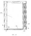
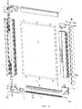
- the mosquito net includes essentially: a box 1 in which the mosquito net 12 is rolled, two (upper and lower) housing seats IS for the mosquito net placed at both ends of the box, a stationary upper guide 4 connected to the upper housing seat IS, a bar handle 10 which is in slidable connection with such foldaway guide means consisting essentially of a chain 11 having an end which is hinged to a support 7 integral with the lower housing seat, as well as a fitting section bar 8 of the bar handle 10 which is secured to the side of the frame opposite to box 1 so as to block the bar handle in the (unrolled) position of use of the mosquito net.
- chain 11 comes out of bar handle 10 (which moves away from box 1) and lies down at the lower side of the frame on a stationary section bar 6 with small thickness which is a fixed seat preventing any crosswise shift of chain 11 which guides mosquito net 12 from the lower side.
- chain 11 does not undergo any shift orthogonal to the plane of mosquito net 12 that is then free from the so-called "sail effect" which, as known, takes place in the presence of wind.
- the upper edge of the mosquito net 12 slides in the stationary upper guide 4, and its lower edge slides in the chain 11, the links of which are hollow and provided with an upper longitudinal slot 11A to allow such sliding (figs. 7A-7E and 9).
- the mosquito net 12 is preferably provided with a peripheral semirigid rubber or plastic edge or frame 12A which is able to keep taut the mosquito net and to avoid the formation of wrinkles (fig. 8) during the sliding and when the mosquito net is in the unrolled position.
- "buttons" 15 secured to the peripheral edge 12A are located at the upper and lower sides of the mosquito net and are able to slide in the stationary upper guide 4 and the hollow chain 11, respectively, thus preventing the mosquito net from being released therefrom.
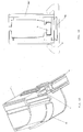
- FIG 2 there is shown the lower portion of the bar handle 10 carrying an angle member 13 which guides the links of chain 11 from the vertical position (rolled mosquito net) to the horizontal position (unrolled mosquito net) and vice versa.
- Such guide angle member 13 is connected to seat 14 for chain 11 inside bar handle 10 (fig. 3).
- the peripheral edge 12A is blocked with its vertical side in a suitable housing arranged in bar handle 10.
- such box 1 is provided with a spring rolling system 2 of the known type as well as end supports 5 for its fastening to the frame in which the relative upper and lower housing seats IS are fitted.
- Supports 5 are closed by suitable plugs 3 also acting as seats for the ends of the self-rolling roller.
- bar handle 10 is fastened to the fitting section bar 8 preferably by a magnetic band arranged both inside the fitting section bar and the bar handle.
- the invention is particularly (even if not exclusively) useful in those case in which the frames are installed in places frequented by handicapped on wheelchair.
- the stationary lower section bar 6 having rounded edges and a thickness of preferably about 3 mm does not hamper the wheels of the wheelchairs.
- the guides or the section bars which are usually provided in the current mosquito nets are instead an obstacle to the free transit of a wheelchair, thus limiting any free movement of the handicapped.
- the fitting section bar 8 is of course missing because in this case the two bar handles 10 are bound to each other.
- the mosquito net described above fully achieves the predetermined purposes, it should be noted that in case of gusts of wind the foldaway chain described above can sometime be raised accidentally due to the so-called “sail effect" of the mosquito net as the above-mentioned thin guide section bar 6 arranged on the floor as described above, even if it prevents the side movements of the chain, does not hinder the movements having also a vertical component which is caused, for example, by the lifting of the chain from the floor just because of the "sail effect".
- the first embodiment of the invention described above has no intermediate opening positions: in other words, the mosquito net can be only installed in a completely rolled or completely unrolled position, which can be difficult in case of very large frames in which two self-rolling mosquito nets opposing to each other are provided. In such case, to pass across the opening of the frame it is necessary at least to re-wind a portion of the mosquito net by one hand and to retain the other portion of the mosquito net by the other hand which otherwise would tend to re-wind suddenly because of the lack of the reciprocal connection of the two portions of the mosquito nets with possible damages.
- a second embodiment of the invention shown in figures 11 to 17C provides further blocking means of the chain in the direction perpendicular to the chain laying plane as well as means to keep the mosquito net also in a partially unrolled position.
- this second embodiment includes a mosquito net of the type described above which is further provided with:
- the latter is able to prevent that the lower end of the bar handle sliding along the lower guide section bar comes out of such section bar which is necessarily very thin in order not to be an obstacle to people, even handicapped on wheelchairs, passing across the opening of the frame on which the mosquito net in installed.
- the foldaway chain 11 is provided with magnetic means M able to co-operate with a stationary guide section bar 6 on the floor with small thickness which is either of ferromagnetic material or provides a longitudinal strip FM of such material so that the magnets M of chain 11 can be magnetically attracted thereby.
- links MC of chain 11 retaining mosquito net 12 are kept in their positions not only according to a horizontal direction crosswise to the chain but also according to the vertical direction.
- Such magnets M are arranged in all or some links MC of chain 11 and are located adjacent to the lower wall thereof which is parallel to the guide section bar 6.
- the embodiment described provides that the guide section bar 6 has a dovetail-shaped cross section able to co-operate with the lower end 10' of the bar handle 10 in order to avoid that accidental "derailments" of the bar handle take place during the mosquito net opening or closure.
- the lower end 10' of the bar handle has of course a shape conjugated to the guide section bar 6.
- a preferably wedge-shaped member EC which is automatically snap-fitted between two adjacent links MC is arranged in the already described angle guide member 13 to block the chain in any intermediate position between the complete opening or closure of the mosquito net with the same "pitch" as the chain.
- the user in order to move the bar handle 10 by unrolling or re-winding mosquito net 12, the user should only "overcome” the resistance of such blocking member EC between two adjoining links that is kept in such position by suitably yielding elastic means.
- magnets M are distributed along chain 11 and not on the guide section bar 6 so as to avoid the excessive accumulation of dirt and metal particles that could be attracted by magnets M. In fact, if the latter would be placed in the stationary guide section bar 6 on the floor, they would quickly give rise to the obstruction of the same unless frequent cleaning are made.
- the stationary support 7 is preferably shaped as a half link of the chain to guarantee the maximum fluidity and smoothness of the movement of extraction from and re-insertion of the chain into the bar handle.
Landscapes
- Engineering & Computer Science (AREA)
- Structural Engineering (AREA)
- Architecture (AREA)
- Civil Engineering (AREA)
- Life Sciences & Earth Sciences (AREA)
- Insects & Arthropods (AREA)
- Pest Control & Pesticides (AREA)
- Catching Or Destruction (AREA)
- Operating, Guiding And Securing Of Roll- Type Closing Members (AREA)
Abstract
Description
- magnetic means to connect the links of the chain to the lower guide section bar;
- elastic snap connection means to retain automatically the mosquito net in a partially unrolled position; and
- slidable fitting means to guide and to retain the ends of the operating bar handle in its seat.
Claims (22)
- A rolling mosquito net for frames provided with foldaway guides, characterized in that it includes in combination: a mosquito net (12) that can be self-rolled into a suitable lateral, vertically disposed rolling-shutter box (1), and is provided with a stationary upper guide means (4) and a movable lower guide means (11) able to be folded away into a control bar handle (10) operated by the user during the mosquito net rolling step and to project outside of such control bar handle during the mosquito net unrolling step, thus ensuring a correct positioning of the unrolled mosquito net (12) and to reduce the overall dimensions of the guide means when the mosquito net is in its rolled position within box (1).
- The rolling mosquito net of the preceding claim, characterized in that said foldaway guide means consists essentially of a chain (11) with an end hinged to a stationary support (7) integral with a housing seat (IS) placed at the lower end of the box.
- The rolling mosquito net of the preceding claim, characterized in that during the unrolling motion of the self-rolling mosquito net (12), chain (11) comes out of bar handle (10) which moves away from box (1) and lies down at the lower side of the frame on a suitable stationary section bar (6) with small thickness which is a fixed seat preventing any crosswise shift of chain (11) which guides mosquito net (12) from the lower side, thus obtaining that chain (11) does not undergo any shift orthogonal to the plane of mosquito net (12) that is then free from the so-called "sail effect".
- The rolling mosquito net according to any claim from 2 on, characterized in that the upper edge of the mosquito net 12 slides in the stationary upper guide 4, and its lower edge slides in the chain 11, the links of which are hollow and provided with an upper longitudinal slot 11A to allow such sliding.
- The rolling mosquito net of the preceding claim, characterized in that the mosquito net (12) is provided with a peripheral semirigid rubber or plastic edge or frame (12A) which is able to keep taut the mosquito net and to avoid the formation of wrinkles during the sliding and when the mosquito net is in the unrolled position.
- The rolling mosquito net of the preceding claim, characterized in that in the lower portion of the bar handle (10) an angle member (13) is located which guides the links of chain (11) from the vertical position (rolled mosquito net) to the horizontal position (unrolled mosquito net) and vice versa, said guide angle member (13) being connected to a seat (14) for chain (11) inside bar handle (10).
- The rolling mosquito net of claim 5 or 6, characterized in that buttons (15) secured to the peripheral edge (12A) are located at the upper and lower sides of the mosquito net (12) and are able to slide in the stationary upper guide (4) and the hollow chain (11), respectively, thus preventing the mosquito net from being released therefrom.
- The rolling mosquito net of claim 5, characterized in that the peripheral semirigid edge (12A) of the mosquito net is blocked with its vertical side opposite to the box (1) in a suitable housing arranged in bar handle (10).
- The rolling mosquito net of any preceding claim, characterized in that such box (1) is provided with a spring rolling system (2) of the known type as well as end supports (5) for its fastening to the frame in which the relative upper and lower housing seats (IS) are fitted, the supports (5) being closed by suitable plugs (3) also acting as seats for the ends of the self-rolling roller.
- The rolling mosquito net of any preceding claim, characterized in that there is provided a fitting section bar (8) of the bar handle (10) which is secured to the side of the frame opposite to box (1) so as to block the bar handle in the (unrolled) position of use of the mosquito net.
- The rolling mosquito net of the preceding claim, characterized in that bar handle (10) is fastened in a removable manner to the fitting section bar (8) by a magnetic band arranged both inside the fitting section bar and the bar handle.
- The rolling mosquito net of any claims from 1 to 9, characterized in that said bar handle (10) is bound to a second bar handle of another specular rolling mosquito net to carry out an installation with two mirror-like opposing mosquito nets, said bar handle being provided with magnetic means co-operating with those of the second bar handle to make a reciprocal connection.
- The rolling mosquito net according to any claim from 10 on, characterized in that in alternative to said magnetic means or bands, a mechanical fitting means of the known type is provided.
- The rolling mosquito net of claim 3, characterized in that said lower section bar (6) has rounded edges and a thickness of about 3 mm so that any obstacle for the wheels of the wheelchairs of the handicapped or the like is avoided and a free transit to the latter also through the frames provided with said mosquito nets is allowed.
- The rolling mosquito net of claim 1, characterized in that it further includes magnetic means (M) to connect said lower movable guide means to a lower guide section bar (6), elastic snap connection means to retain automatically the mosquito net in a partially unrolled position, and slidable fitting means to guide and to retain the ends of the operating bar handle in its seat.
- The rolling mosquito net of the preceding claim, characterized in that said foldaway guide means consists essentially of a chain (11) having an end which is hinged to a stationary support (7) integral with the lower housing seat (IS) located at the lower end of the box.
- The rolling mosquito net of claim 15 or 16, characterized in that said foldaway chain (11) is provided with magnetic means (M) able to co-operate with a stationary guide section bar (6) on the floor with small thickness which is either of ferromagnetic material or provides a longitudinal strip (FM) of such material so that the magnets (M) of chain (11) can be magnetically attracted thereby so that the links (MC) of chain (11) retaining mosquito net (12) are kept in their positions not only according to a horizontal direction crosswise to the chain but also according to the vertical direction.
- The rolling mosquito net of the preceding claim, characterized in that said magnets (M) are arranged in all or some links (MC) of chain (11) and are located adjacent to the lower wall thereof which is parallel to the guide section bar (6).
- The rolling mosquito net of claim 14 or 17, characterized in that said guide section bar (6) has a dovetail-shaped cross section able to co-operate with the lower end (10') of the bar handle (10) in order to avoid that accidental "derailments" of the bar handle take place during the mosquito net opening or closure, said lower end (10') of the bar handle having a shape conjugated to the guide section bar (6).
- The rolling mosquito net of any claims from 15 to 19, characterized in that an angle member (13) which guides the links of chain (11) from the vertical position (rolled mosquito net) to the horizontal position (unrolled mosquito net) and vice versa is arranged in the lower portion of the bar handle (10), which angle guide member (13) is provided with a preferably wedge-shaped member (EC) which is automatically snap-fitted between two adjacent links (MC) to block the chain in any intermediate position between the complete opening or closure of the mosquito net with the same "pitch" as the chain so that in order to move the bar handle (10) by unrolling or re-winding mosquito net (12), the user should only "overcome" the resistance of such blocking member (EC) between two adjoining links that is kept in such position by suitably yielding elastic means.
- The rolling mosquito net of the preceding claim, characterized in that said snap-fitting member (EC) which is pressed between two adjoining links (MC) by a preferably helical spring (S) has generally the shape of a truncated pyramid so that because of the movement of the bar handle (10) the fitting member (EC) engaged between links (MC) interferes with its inclined walls against the bevelled edge of the lower wall (I) of one link, thus generating a thrust tending to move it away from the chain against the elastic thrust of spring (S) .
- The rolling mosquito net of the preceding claim, characterized in that the stationary support (7) is shaped as a half link of the chain to guarantee the maximum fluidity and smoothness of the movement of extraction from and re-insertion of the chain into the bar handle.
Applications Claiming Priority (4)
| Application Number | Priority Date | Filing Date | Title |
|---|---|---|---|
| IT2002RM000029A ITRM20020029A1 (en) | 2002-01-23 | 2002-01-23 | ROLL-UP MOSQUITO NET FOR FIXTURES EQUIPPED WITH RETRACTABLE GUIDES. |
| ITRM20020029 | 2002-01-23 | ||
| ITRM20020657 | 2002-12-30 | ||
| ITRM20020657 ITRM20020657A1 (en) | 2002-12-30 | 2002-12-30 | ROLL-UP MOSQUITO NET WITH HIDDEN RETRACTABLE GUIDES. |
Publications (3)
| Publication Number | Publication Date |
|---|---|
| EP1333148A2 true EP1333148A2 (en) | 2003-08-06 |
| EP1333148A3 EP1333148A3 (en) | 2004-06-02 |
| EP1333148B1 EP1333148B1 (en) | 2007-09-26 |
Family
ID=26332847
Family Applications (1)
| Application Number | Title | Priority Date | Filing Date |
|---|---|---|---|
| EP03425031A Expired - Lifetime EP1333148B1 (en) | 2002-01-23 | 2003-01-23 | A rolling mosquito net for frames provided with foldaway guides |
Country Status (5)
| Country | Link |
|---|---|
| EP (1) | EP1333148B1 (en) |
| AT (1) | ATE374303T1 (en) |
| DE (1) | DE60316484T2 (en) |
| ES (1) | ES2294259T3 (en) |
| PT (1) | PT1333148E (en) |
Cited By (25)
| Publication number | Priority date | Publication date | Assignee | Title |
|---|---|---|---|---|
| EP1460233A1 (en) * | 2003-03-18 | 2004-09-22 | Agila S.R.L. | A roll-up mosquito screen |
| WO2006006194A1 (en) * | 2004-07-15 | 2006-01-19 | Mv Line Srl | Improved rolling mosquito net provided with foldaway guides |
| EP1640554A4 (en) * | 2003-05-21 | 2009-03-11 | Seiki Hanbai Co Ltd | Winding-up screen device |
| EP1905944A3 (en) * | 2006-09-21 | 2009-05-13 | EFFE S.r.l. | Roller screen device |
| EP2011954A3 (en) * | 2007-07-04 | 2009-08-05 | Genius Italia S.r.L. | Roller fly-screen with concealed guides |
| EP1783320A4 (en) * | 2004-06-14 | 2010-04-14 | Metaco Inc | SCREEN DEVICE |
| ITMI20090131A1 (en) * | 2009-02-03 | 2010-08-04 | Primed S R L | SCREENING SCREEN DEVICE PERFECTED |
| US7810543B2 (en) | 2007-12-11 | 2010-10-12 | Effe S.R.L. | Roller screen device |
| EP2341210A2 (en) | 2009-12-30 | 2011-07-06 | Unilux Nederland B.V. | Handle and a locking clip for use with a screen device, and screen device equipped therewith |
| EP2407628A2 (en) | 2010-07-12 | 2012-01-18 | Argyrios Papadopoulos | Anti-mosquito screen restraint system within articulated guide |
| ITPD20110098A1 (en) * | 2011-03-30 | 2012-10-01 | Dennis Buggio | STRUCTURAL ELEMENTS OF REWINDABLE MOSQUITO-NETS |
| CN102747929A (en) * | 2012-06-14 | 2012-10-24 | 广铝集团有限公司 | Barrier-free vertical hinged door window with gauze element |
| ITBO20110443A1 (en) * | 2011-07-26 | 2013-01-27 | Mv Line Spa | GROUP OF MOVEMENT FOR MOSQUITO NETS, CURTAINS AND LAMINAR ELEMENTS IN GENERAL |
| ITBO20110442A1 (en) * | 2011-07-26 | 2013-01-27 | Mv Line Spa | GROUP OF MOVEMENT FOR MOSQUITO NETS, CURTAINS AND LAMINAR ELEMENTS IN GENERAL |
| ITRE20110101A1 (en) * | 2011-11-23 | 2013-05-24 | Rami S R L Off | DEVICE TO SCREEN AN OPENING, TYPICALLY WITH A MOSQUITO NET |
| ES2399268R1 (en) * | 2011-09-13 | 2013-08-01 | Herrero Llopis Maria Amparo | LINK CHAIN FOR RETRACTABLE SCREENS |
| RU2491400C2 (en) * | 2008-08-06 | 2013-08-27 | Метако Инк. | Screen device |
| ITCZ20120009A1 (en) * | 2012-08-02 | 2014-02-03 | Apz Sistemi Srl | MOSQUITO NET FOR WINDOWS EQUIPPED WITH CONCEALED GUIDES |
| EP2773831A1 (en) | 2011-11-02 | 2014-09-10 | MV Line S.p.A. | Movable mosquito screen, particularly for windows, doors and the like |
| WO2015121817A1 (en) * | 2014-02-17 | 2015-08-20 | Apz Sistemi Srl | Shielding for doors or windows frame equipped with side-scrolling lateral box |
| EP3023574A1 (en) * | 2014-11-21 | 2016-05-25 | Mark Andrew Huskinson | Retractable fly-screen with a handicapped accessible lower guide |
| EP3037619A1 (en) * | 2014-12-23 | 2016-06-29 | APZ Sistemi S.r.l | Shielding for doors or windows frame equipped with side-scrolling lateral box suitable to be free of lower guide |
| KR20220129414A (en) * | 2021-03-16 | 2022-09-23 | (주)인익스 | Detachable functional net storage assembly and window assembly including same |
| IT202400004342A1 (en) * | 2024-02-28 | 2025-08-28 | Biessebi S R L | SCREENING APPARATUS FOR SCREENING AN OPENING PROVIDED WITH A LOCKING UNIT FOR LOCKING IT IN A SCREENING POSITION OF THE OPENING |
| IT202400012982A1 (en) * | 2024-06-06 | 2025-12-06 | Mv Line Spa | TELESCOPIC MOVEMENT SYSTEM FOR SIDE-SLIDING SCREENS |
Families Citing this family (1)
| Publication number | Priority date | Publication date | Assignee | Title |
|---|---|---|---|---|
| WO2025163421A2 (en) * | 2024-02-01 | 2025-08-07 | Di Girolamo Gianpiero | System for opening and sliding a mosquito net |
Family Cites Families (3)
| Publication number | Priority date | Publication date | Assignee | Title |
|---|---|---|---|---|
| FR2602539B1 (en) * | 1986-08-11 | 1989-06-09 | Hayashiguchi Seizo | WINDOW SCREEN |
| US6186212B1 (en) * | 1998-06-11 | 2001-02-13 | Metaco Inc. | Screen device |
| US6318438B1 (en) * | 2000-04-18 | 2001-11-20 | Seiki Hanbai Co., Ltd. | Net guide for side-sliding wire screen |
-
2003
- 2003-01-23 ES ES03425031T patent/ES2294259T3/en not_active Expired - Lifetime
- 2003-01-23 PT PT03425031T patent/PT1333148E/en unknown
- 2003-01-23 DE DE60316484T patent/DE60316484T2/en not_active Expired - Lifetime
- 2003-01-23 EP EP03425031A patent/EP1333148B1/en not_active Expired - Lifetime
- 2003-01-23 AT AT03425031T patent/ATE374303T1/en not_active IP Right Cessation
Cited By (27)
| Publication number | Priority date | Publication date | Assignee | Title |
|---|---|---|---|---|
| EP1460233A1 (en) * | 2003-03-18 | 2004-09-22 | Agila S.R.L. | A roll-up mosquito screen |
| EP1640554A4 (en) * | 2003-05-21 | 2009-03-11 | Seiki Hanbai Co Ltd | Winding-up screen device |
| EP1783320A4 (en) * | 2004-06-14 | 2010-04-14 | Metaco Inc | SCREEN DEVICE |
| WO2006006194A1 (en) * | 2004-07-15 | 2006-01-19 | Mv Line Srl | Improved rolling mosquito net provided with foldaway guides |
| EP1905944A3 (en) * | 2006-09-21 | 2009-05-13 | EFFE S.r.l. | Roller screen device |
| EP2011954A3 (en) * | 2007-07-04 | 2009-08-05 | Genius Italia S.r.L. | Roller fly-screen with concealed guides |
| US7810543B2 (en) | 2007-12-11 | 2010-10-12 | Effe S.R.L. | Roller screen device |
| RU2491400C2 (en) * | 2008-08-06 | 2013-08-27 | Метако Инк. | Screen device |
| ITMI20090131A1 (en) * | 2009-02-03 | 2010-08-04 | Primed S R L | SCREENING SCREEN DEVICE PERFECTED |
| EP2341210A2 (en) | 2009-12-30 | 2011-07-06 | Unilux Nederland B.V. | Handle and a locking clip for use with a screen device, and screen device equipped therewith |
| EP2407628A2 (en) | 2010-07-12 | 2012-01-18 | Argyrios Papadopoulos | Anti-mosquito screen restraint system within articulated guide |
| ITPD20110098A1 (en) * | 2011-03-30 | 2012-10-01 | Dennis Buggio | STRUCTURAL ELEMENTS OF REWINDABLE MOSQUITO-NETS |
| ITBO20110443A1 (en) * | 2011-07-26 | 2013-01-27 | Mv Line Spa | GROUP OF MOVEMENT FOR MOSQUITO NETS, CURTAINS AND LAMINAR ELEMENTS IN GENERAL |
| ITBO20110442A1 (en) * | 2011-07-26 | 2013-01-27 | Mv Line Spa | GROUP OF MOVEMENT FOR MOSQUITO NETS, CURTAINS AND LAMINAR ELEMENTS IN GENERAL |
| ES2399268R1 (en) * | 2011-09-13 | 2013-08-01 | Herrero Llopis Maria Amparo | LINK CHAIN FOR RETRACTABLE SCREENS |
| EP2773831A1 (en) | 2011-11-02 | 2014-09-10 | MV Line S.p.A. | Movable mosquito screen, particularly for windows, doors and the like |
| ITRE20110101A1 (en) * | 2011-11-23 | 2013-05-24 | Rami S R L Off | DEVICE TO SCREEN AN OPENING, TYPICALLY WITH A MOSQUITO NET |
| CN102747929B (en) * | 2012-06-14 | 2015-01-07 | 广铝集团有限公司 | Barrier-free vertical hinged door window with gauze element |
| CN102747929A (en) * | 2012-06-14 | 2012-10-24 | 广铝集团有限公司 | Barrier-free vertical hinged door window with gauze element |
| ITCZ20120009A1 (en) * | 2012-08-02 | 2014-02-03 | Apz Sistemi Srl | MOSQUITO NET FOR WINDOWS EQUIPPED WITH CONCEALED GUIDES |
| WO2015121817A1 (en) * | 2014-02-17 | 2015-08-20 | Apz Sistemi Srl | Shielding for doors or windows frame equipped with side-scrolling lateral box |
| EP3023574A1 (en) * | 2014-11-21 | 2016-05-25 | Mark Andrew Huskinson | Retractable fly-screen with a handicapped accessible lower guide |
| EP3037619A1 (en) * | 2014-12-23 | 2016-06-29 | APZ Sistemi S.r.l | Shielding for doors or windows frame equipped with side-scrolling lateral box suitable to be free of lower guide |
| KR20220129414A (en) * | 2021-03-16 | 2022-09-23 | (주)인익스 | Detachable functional net storage assembly and window assembly including same |
| IT202400004342A1 (en) * | 2024-02-28 | 2025-08-28 | Biessebi S R L | SCREENING APPARATUS FOR SCREENING AN OPENING PROVIDED WITH A LOCKING UNIT FOR LOCKING IT IN A SCREENING POSITION OF THE OPENING |
| IT202400012982A1 (en) * | 2024-06-06 | 2025-12-06 | Mv Line Spa | TELESCOPIC MOVEMENT SYSTEM FOR SIDE-SLIDING SCREENS |
| EP4660411A1 (en) * | 2024-06-06 | 2025-12-10 | MV Line SpA | Telescopic handling system for lateral sliding shields |
Also Published As
| Publication number | Publication date |
|---|---|
| PT1333148E (en) | 2007-12-24 |
| EP1333148B1 (en) | 2007-09-26 |
| ATE374303T1 (en) | 2007-10-15 |
| ES2294259T3 (en) | 2008-04-01 |
| EP1333148A3 (en) | 2004-06-02 |
| DE60316484D1 (en) | 2007-11-08 |
| DE60316484T2 (en) | 2008-07-03 |
Similar Documents
| Publication | Publication Date | Title |
|---|---|---|
| EP1333148B1 (en) | A rolling mosquito net for frames provided with foldaway guides | |
| AU2008207626B2 (en) | Head rail assembly | |
| US3149665A (en) | Roller type screens for windows | |
| WO2007133445A2 (en) | Assembly to lock a storm curtain adjacent to an opening in a building | |
| US11643869B2 (en) | Hem bar for use with an architectural-structure covering | |
| EP3271540B1 (en) | Screen device | |
| JP6570838B2 (en) | Waterproof shutter | |
| KR101973968B1 (en) | Both sides end supporting structure of mosquito net | |
| EP1419306B1 (en) | A reversible window, use thereof and a guide device for a reversible window | |
| KR101444941B1 (en) | A Apparatus for Fixing Side of Roller Blind | |
| EP0370550A1 (en) | Roll up door | |
| JPH06158961A (en) | Screen door device | |
| US20230228145A1 (en) | Low Profile, Garage Door Attachment, Which Deters Loose Debris From Entering the Contained Space | |
| KR100773432B1 (en) | Installation structure of roll winding screen for door | |
| JP2001248370A (en) | Guide rail of roll type storage screen door | |
| JPH0513910Y2 (en) | ||
| JP3354586B2 (en) | Assembled screen door device | |
| KR200283707Y1 (en) | Window structure having a rewinding web apparatus | |
| JPH0328710Y2 (en) | ||
| AU718335B2 (en) | Roll up blind and cord guide unit | |
| EP1781886B1 (en) | Improved rolling mosquito net provided with foldaway guides | |
| JPH0642277A (en) | Roller screen for aperture coating on walls or pitched roofs | |
| JP2547706Y2 (en) | Insect screen | |
| JP3958670B2 (en) | Switchgear | |
| JP2844159B2 (en) | Roll-up screen door |
Legal Events
| Date | Code | Title | Description |
|---|---|---|---|
| PUAI | Public reference made under article 153(3) epc to a published international application that has entered the european phase |
Free format text: ORIGINAL CODE: 0009012 |
|
| AK | Designated contracting states |
Designated state(s): AT BE BG CH CY CZ DE DK EE ES FI FR GB GR HU IE IT LI LU MC NL PT SE SI SK TR |
|
| AX | Request for extension of the european patent |
Extension state: AL LT LV MK RO |
|
| RIC1 | Information provided on ipc code assigned before grant |
Ipc: 7E 06B 9/54 A Ipc: 7E 06B 9/58 B |
|
| PUAL | Search report despatched |
Free format text: ORIGINAL CODE: 0009013 |
|
| AK | Designated contracting states |
Kind code of ref document: A3 Designated state(s): AT BE BG CH CY CZ DE DK EE ES FI FR GB GR HU IE IT LI LU MC NL PT SE SI SK TR |
|
| AX | Request for extension of the european patent |
Extension state: AL LT LV MK RO |
|
| RIC1 | Information provided on ipc code assigned before grant |
Ipc: 7E 06B 9/54 A Ipc: 7E 06B 9/262 B Ipc: 7E 06B 9/58 B |
|
| 17P | Request for examination filed |
Effective date: 20041125 |
|
| AKX | Designation fees paid |
Designated state(s): AT BE BG CH CY CZ DE DK EE ES FI FR GB GR HU IE IT LI LU MC NL PT SE SI SK TR |
|
| 17Q | First examination report despatched |
Effective date: 20050530 |
|
| TPAC | Observations filed by third parties |
Free format text: ORIGINAL CODE: EPIDOSNTIPA |
|
| GRAP | Despatch of communication of intention to grant a patent |
Free format text: ORIGINAL CODE: EPIDOSNIGR1 |
|
| GRAS | Grant fee paid |
Free format text: ORIGINAL CODE: EPIDOSNIGR3 |
|
| GRAA | (expected) grant |
Free format text: ORIGINAL CODE: 0009210 |
|
| RAP1 | Party data changed (applicant data changed or rights of an application transferred) |
Owner name: MV LINE S.R.L |
|
| AK | Designated contracting states |
Kind code of ref document: B1 Designated state(s): AT BE BG CH CY CZ DE DK EE ES FI FR GB GR HU IE IT LI LU MC NL PT SE SI SK TR |
|
| REG | Reference to a national code |
Ref country code: GB Ref legal event code: FG4D |
|
| REG | Reference to a national code |
Ref country code: CH Ref legal event code: EP |
|
| REF | Corresponds to: |
Ref document number: 60316484 Country of ref document: DE Date of ref document: 20071108 Kind code of ref document: P |
|
| REG | Reference to a national code |
Ref country code: IE Ref legal event code: FG4D |
|
| REG | Reference to a national code |
Ref country code: PT Ref legal event code: SC4A Free format text: AVAILABILITY OF NATIONAL TRANSLATION Effective date: 20071213 |
|
| PG25 | Lapsed in a contracting state [announced via postgrant information from national office to epo] |
Ref country code: FI Free format text: LAPSE BECAUSE OF FAILURE TO SUBMIT A TRANSLATION OF THE DESCRIPTION OR TO PAY THE FEE WITHIN THE PRESCRIBED TIME-LIMIT Effective date: 20070926 |
|
| REG | Reference to a national code |
Ref country code: CH Ref legal event code: NV Representative=s name: PATENTS & TECHNOLOGY SURVEYS SA |
|
| REG | Reference to a national code |
Ref country code: GR Ref legal event code: EP Ref document number: 20070403746 Country of ref document: GR |
|
| REG | Reference to a national code |
Ref country code: ES Ref legal event code: FG2A Ref document number: 2294259 Country of ref document: ES Kind code of ref document: T3 |
|
| PG25 | Lapsed in a contracting state [announced via postgrant information from national office to epo] |
Ref country code: CZ Free format text: LAPSE BECAUSE OF FAILURE TO SUBMIT A TRANSLATION OF THE DESCRIPTION OR TO PAY THE FEE WITHIN THE PRESCRIBED TIME-LIMIT Effective date: 20070926 Ref country code: SK Free format text: LAPSE BECAUSE OF FAILURE TO SUBMIT A TRANSLATION OF THE DESCRIPTION OR TO PAY THE FEE WITHIN THE PRESCRIBED TIME-LIMIT Effective date: 20070926 |
|
| ET | Fr: translation filed | ||
| PG25 | Lapsed in a contracting state [announced via postgrant information from national office to epo] |
Ref country code: SE Free format text: LAPSE BECAUSE OF FAILURE TO SUBMIT A TRANSLATION OF THE DESCRIPTION OR TO PAY THE FEE WITHIN THE PRESCRIBED TIME-LIMIT Effective date: 20071226 |
|
| PG25 | Lapsed in a contracting state [announced via postgrant information from national office to epo] |
Ref country code: DK Free format text: LAPSE BECAUSE OF FAILURE TO SUBMIT A TRANSLATION OF THE DESCRIPTION OR TO PAY THE FEE WITHIN THE PRESCRIBED TIME-LIMIT Effective date: 20070926 |
|
| PLBE | No opposition filed within time limit |
Free format text: ORIGINAL CODE: 0009261 |
|
| STAA | Information on the status of an ep patent application or granted ep patent |
Free format text: STATUS: NO OPPOSITION FILED WITHIN TIME LIMIT |
|
| PG25 | Lapsed in a contracting state [announced via postgrant information from national office to epo] |
Ref country code: MC Free format text: LAPSE BECAUSE OF NON-PAYMENT OF DUE FEES Effective date: 20080131 |
|
| 26N | No opposition filed |
Effective date: 20080627 |
|
| PG25 | Lapsed in a contracting state [announced via postgrant information from national office to epo] |
Ref country code: EE Free format text: LAPSE BECAUSE OF FAILURE TO SUBMIT A TRANSLATION OF THE DESCRIPTION OR TO PAY THE FEE WITHIN THE PRESCRIBED TIME-LIMIT Effective date: 20070926 Ref country code: IE Free format text: LAPSE BECAUSE OF NON-PAYMENT OF DUE FEES Effective date: 20080123 |
|
| PG25 | Lapsed in a contracting state [announced via postgrant information from national office to epo] |
Ref country code: SI Free format text: LAPSE BECAUSE OF FAILURE TO SUBMIT A TRANSLATION OF THE DESCRIPTION OR TO PAY THE FEE WITHIN THE PRESCRIBED TIME-LIMIT Effective date: 20070926 |
|
| PG25 | Lapsed in a contracting state [announced via postgrant information from national office to epo] |
Ref country code: CY Free format text: LAPSE BECAUSE OF FAILURE TO SUBMIT A TRANSLATION OF THE DESCRIPTION OR TO PAY THE FEE WITHIN THE PRESCRIBED TIME-LIMIT Effective date: 20070926 |
|
| PG25 | Lapsed in a contracting state [announced via postgrant information from national office to epo] |
Ref country code: BG Free format text: LAPSE BECAUSE OF FAILURE TO SUBMIT A TRANSLATION OF THE DESCRIPTION OR TO PAY THE FEE WITHIN THE PRESCRIBED TIME-LIMIT Effective date: 20071226 |
|
| PGFP | Annual fee paid to national office [announced via postgrant information from national office to epo] |
Ref country code: CH Payment date: 20100215 Year of fee payment: 8 Ref country code: ES Payment date: 20100226 Year of fee payment: 8 Ref country code: PT Payment date: 20100121 Year of fee payment: 8 |
|
| PGFP | Annual fee paid to national office [announced via postgrant information from national office to epo] |
Ref country code: FR Payment date: 20100212 Year of fee payment: 8 |
|
| PGFP | Annual fee paid to national office [announced via postgrant information from national office to epo] |
Ref country code: AT Payment date: 20100129 Year of fee payment: 8 Ref country code: DE Payment date: 20100201 Year of fee payment: 8 Ref country code: GB Payment date: 20100302 Year of fee payment: 8 Ref country code: TR Payment date: 20100121 Year of fee payment: 8 |
|
| PG25 | Lapsed in a contracting state [announced via postgrant information from national office to epo] |
Ref country code: LU Free format text: LAPSE BECAUSE OF NON-PAYMENT OF DUE FEES Effective date: 20080123 Ref country code: HU Free format text: LAPSE BECAUSE OF FAILURE TO SUBMIT A TRANSLATION OF THE DESCRIPTION OR TO PAY THE FEE WITHIN THE PRESCRIBED TIME-LIMIT Effective date: 20080327 |
|
| PGFP | Annual fee paid to national office [announced via postgrant information from national office to epo] |
Ref country code: BE Payment date: 20100310 Year of fee payment: 8 Ref country code: NL Payment date: 20100121 Year of fee payment: 8 |
|
| PGFP | Annual fee paid to national office [announced via postgrant information from national office to epo] |
Ref country code: GR Payment date: 20100128 Year of fee payment: 8 |
|
| REG | Reference to a national code |
Ref country code: CH Ref legal event code: PFA Owner name: MV LINE S.R.L Free format text: MV LINE S.R.L#VIA SAMMICHELE, N.C. ZONA PIP#70021 ACQUAVIVA DELLE FONTI (IT) -TRANSFER TO- MV LINE S.R.L#VIA SAMMICHELE, N.C. ZONA PIP#70021 ACQUAVIVA DELLE FONTI (IT) |
|
| BERE | Be: lapsed |
Owner name: MV LINE S.R.L Effective date: 20110131 |
|
| REG | Reference to a national code |
Ref country code: PT Ref legal event code: MM4A Free format text: LAPSE DUE TO NON-PAYMENT OF FEES Effective date: 20110725 |
|
| REG | Reference to a national code |
Ref country code: NL Ref legal event code: V1 Effective date: 20110801 |
|
| REG | Reference to a national code |
Ref country code: CH Ref legal event code: PL |
|
| GBPC | Gb: european patent ceased through non-payment of renewal fee |
Effective date: 20110123 |
|
| REG | Reference to a national code |
Ref country code: FR Ref legal event code: ST Effective date: 20110930 |
|
| PG25 | Lapsed in a contracting state [announced via postgrant information from national office to epo] |
Ref country code: PT Free format text: LAPSE BECAUSE OF NON-PAYMENT OF DUE FEES Effective date: 20110725 Ref country code: CH Free format text: LAPSE BECAUSE OF NON-PAYMENT OF DUE FEES Effective date: 20110131 Ref country code: FR Free format text: LAPSE BECAUSE OF NON-PAYMENT OF DUE FEES Effective date: 20110131 Ref country code: LI Free format text: LAPSE BECAUSE OF NON-PAYMENT OF DUE FEES Effective date: 20110131 |
|
| PG25 | Lapsed in a contracting state [announced via postgrant information from national office to epo] |
Ref country code: AT Free format text: LAPSE BECAUSE OF NON-PAYMENT OF DUE FEES Effective date: 20110123 Ref country code: GB Free format text: LAPSE BECAUSE OF NON-PAYMENT OF DUE FEES Effective date: 20110123 Ref country code: GR Free format text: LAPSE BECAUSE OF NON-PAYMENT OF DUE FEES Effective date: 20110802 Ref country code: BE Free format text: LAPSE BECAUSE OF NON-PAYMENT OF DUE FEES Effective date: 20110131 |
|
| PG25 | Lapsed in a contracting state [announced via postgrant information from national office to epo] |
Ref country code: NL Free format text: LAPSE BECAUSE OF NON-PAYMENT OF DUE FEES Effective date: 20110801 |
|
| REG | Reference to a national code |
Ref country code: DE Ref legal event code: R119 Ref document number: 60316484 Country of ref document: DE Effective date: 20110802 |
|
| REG | Reference to a national code |
Ref country code: ES Ref legal event code: FD2A Effective date: 20120220 |
|
| PG25 | Lapsed in a contracting state [announced via postgrant information from national office to epo] |
Ref country code: ES Free format text: LAPSE BECAUSE OF NON-PAYMENT OF DUE FEES Effective date: 20110124 |
|
| PG25 | Lapsed in a contracting state [announced via postgrant information from national office to epo] |
Ref country code: DE Free format text: LAPSE BECAUSE OF NON-PAYMENT OF DUE FEES Effective date: 20110802 |
|
| PG25 | Lapsed in a contracting state [announced via postgrant information from national office to epo] |
Ref country code: TR Free format text: LAPSE BECAUSE OF NON-PAYMENT OF DUE FEES Effective date: 20110123 |
|
| PGFP | Annual fee paid to national office [announced via postgrant information from national office to epo] |
Ref country code: IT Payment date: 20220124 Year of fee payment: 20 |