EP1332928B1 - Method of folding an airbag - Google Patents
Method of folding an airbag Download PDFInfo
- Publication number
- EP1332928B1 EP1332928B1 EP03002529A EP03002529A EP1332928B1 EP 1332928 B1 EP1332928 B1 EP 1332928B1 EP 03002529 A EP03002529 A EP 03002529A EP 03002529 A EP03002529 A EP 03002529A EP 1332928 B1 EP1332928 B1 EP 1332928B1
- Authority
- EP
- European Patent Office
- Prior art keywords
- airbag
- connection element
- folding
- base plate
- cover
- Prior art date
- Legal status (The legal status is an assumption and is not a legal conclusion. Google has not performed a legal analysis and makes no representation as to the accuracy of the status listed.)
- Expired - Lifetime
Links
Images


Classifications
-
- B—PERFORMING OPERATIONS; TRANSPORTING
- B60—VEHICLES IN GENERAL
- B60R—VEHICLES, VEHICLE FITTINGS, OR VEHICLE PARTS, NOT OTHERWISE PROVIDED FOR
- B60R21/00—Arrangements or fittings on vehicles for protecting or preventing injuries to occupants or pedestrians in case of accidents or other traffic risks
- B60R21/02—Occupant safety arrangements or fittings, e.g. crash pads
- B60R21/16—Inflatable occupant restraints or confinements designed to inflate upon impact or impending impact, e.g. air bags
- B60R21/20—Arrangements for storing inflatable members in their non-use or deflated condition; Arrangement or mounting of air bag modules or components
- B60R21/201—Packaging straps or envelopes for inflatable members
-
- B—PERFORMING OPERATIONS; TRANSPORTING
- B60—VEHICLES IN GENERAL
- B60R—VEHICLES, VEHICLE FITTINGS, OR VEHICLE PARTS, NOT OTHERWISE PROVIDED FOR
- B60R21/00—Arrangements or fittings on vehicles for protecting or preventing injuries to occupants or pedestrians in case of accidents or other traffic risks
- B60R21/02—Occupant safety arrangements or fittings, e.g. crash pads
- B60R21/16—Inflatable occupant restraints or confinements designed to inflate upon impact or impending impact, e.g. air bags
- B60R21/23—Inflatable members
- B60R21/237—Inflatable members characterised by the way they are folded
-
- B—PERFORMING OPERATIONS; TRANSPORTING
- B60—VEHICLES IN GENERAL
- B60R—VEHICLES, VEHICLE FITTINGS, OR VEHICLE PARTS, NOT OTHERWISE PROVIDED FOR
- B60R21/00—Arrangements or fittings on vehicles for protecting or preventing injuries to occupants or pedestrians in case of accidents or other traffic risks
- B60R21/02—Occupant safety arrangements or fittings, e.g. crash pads
- B60R21/16—Inflatable occupant restraints or confinements designed to inflate upon impact or impending impact, e.g. air bags
- B60R21/20—Arrangements for storing inflatable members in their non-use or deflated condition; Arrangement or mounting of air bag modules or components
-
- B—PERFORMING OPERATIONS; TRANSPORTING
- B60—VEHICLES IN GENERAL
- B60R—VEHICLES, VEHICLE FITTINGS, OR VEHICLE PARTS, NOT OTHERWISE PROVIDED FOR
- B60R21/00—Arrangements or fittings on vehicles for protecting or preventing injuries to occupants or pedestrians in case of accidents or other traffic risks
- B60R21/02—Occupant safety arrangements or fittings, e.g. crash pads
- B60R21/16—Inflatable occupant restraints or confinements designed to inflate upon impact or impending impact, e.g. air bags
- B60R21/23—Inflatable members
- B60R21/231—Inflatable members characterised by their shape, construction or spatial configuration
- B60R21/2334—Expansion control features
- B60R21/2338—Tethers
- B60R2021/23382—Internal tether means
-
- B—PERFORMING OPERATIONS; TRANSPORTING
- B60—VEHICLES IN GENERAL
- B60R—VEHICLES, VEHICLE FITTINGS, OR VEHICLE PARTS, NOT OTHERWISE PROVIDED FOR
- B60R21/00—Arrangements or fittings on vehicles for protecting or preventing injuries to occupants or pedestrians in case of accidents or other traffic risks
- B60R21/02—Occupant safety arrangements or fittings, e.g. crash pads
- B60R21/16—Inflatable occupant restraints or confinements designed to inflate upon impact or impending impact, e.g. air bags
- B60R21/23—Inflatable members
- B60R21/237—Inflatable members characterised by the way they are folded
- B60R2021/2375—Folding devices
-
- B—PERFORMING OPERATIONS; TRANSPORTING
- B60—VEHICLES IN GENERAL
- B60R—VEHICLES, VEHICLE FITTINGS, OR VEHICLE PARTS, NOT OTHERWISE PROVIDED FOR
- B60R21/00—Arrangements or fittings on vehicles for protecting or preventing injuries to occupants or pedestrians in case of accidents or other traffic risks
- B60R21/02—Occupant safety arrangements or fittings, e.g. crash pads
- B60R21/16—Inflatable occupant restraints or confinements designed to inflate upon impact or impending impact, e.g. air bags
- B60R21/20—Arrangements for storing inflatable members in their non-use or deflated condition; Arrangement or mounting of air bag modules or components
- B60R21/217—Inflation fluid source retainers, e.g. reaction canisters; Connection of bags, covers, diffusers or inflation fluid sources therewith or together
Definitions
- the invention relates to a process for folding an airbag of an airbag module, having the steps of: arranging the airbag and a base plate on a receiver of a folding device, with the airbag secured to the base plate, and stretching the airbag out.
- the invention also relates to a device for performing this process and to an airbag module having a base plate and an airbag secured to the latter.
- US-5,360,387 relates to an automated system for folding a vehicle airbag, wherein a machine having numerous movable arms controlled by a controller is provided, an edge folding assembly of the machine has five arms, including a center arm, two outer blades and two outwardly facing U-channel forks, which reside between respective outer blades and the center arm, whereby the edge folding assembly moves forward so that all of its five arms engage an unfolded airbag.
- EP 0 712 760 relates to a method for folding a gas bag for a vehicle occupant protection system, wherein the airbag is folded from a deflated, flattened and spread-out condition into a shape adapted to the interior space of a receiving compartment by substantially rotating the junction section relative to the securing section of the airbag.
- EP 0 825 072 relates to a method for folding an airbag having the steps of inserting a first plunger into an opening in a lower half of the airbag such that it pushes the upper part away from the lower part, the upper part is then clamped between the first plunger and the second plunger, thereafter the airbag is folded upward such that a plurality of radial folds is created, which are then folded inward. Following that, a hollow die is then placed over the folded airbag, whereas the upper end of the airbag in a central portion of the airbag is twisted in different directions while a third plunger is placed over the end face of the folded airbag.
- DE 195 35 564 relates to a method for folding an airbag, wherein the empty airbag is spread out and gathered in towards a center to achieve a folded airbag, wherein the airbag is gathered inside a fixed vertical profiled section having a top and a bottom separated by a distance, and wherein only a view gathering tools and only a view operations are necessary to gather the airbag.
- a process for folding an airbag of an airbag module having the steps of: arranging the airbag and a base plate on a receiver of a folding device in the form of a piston, with the airbag secured to the base plate; arranging a housing of the airbag module on a holding device of the folding device in the form of a substantially vertically arranged tube with circular cross-section; fixing a portion of the airbag remote from the base plate to an upper part of the housing of the airbag module.
- the cylindrical holding device with airbag module are movable substantially vertically relative to the receiver. In one position of the folding process the airbag is stretched out within the tubular holding device between the portion fixed to the airbag module housing and the portion fixed to the base plate. No indication is given of how to fix the portion of the airbag remote from the base plate to the upper part of the airbag module housing.
- a portion of the airbag remote from the base plate is to be arranged or mounted or secured on or to a holding device of the folding device, and the airbag is subsequently to be stretched out by pulling this secured portion.
- the pulling is performed by means of a movement of the holding device relative to the receiver. During this movement, alternatively, the holding device or the receiver may be moved individually or in combination relative to one another.
- the airbag is not pushed from the inside outwards in the direction of stretching out, but rather it is pulled on its outside with the aid of a holding device. This pulling may be performed in a manner giving a reliable procedure, using a device that can be produced at low cost.
- the associated device and the correspondingly shaped airbag module are particularly useful if the base plate of the airbag module is substantially closed in the direction of stretching out.
- the airbag can be stretched out although no die or piston can be pushed in through the substantially closed base plate for the purpose of stretching out the airbag.
- the process according to the invention can also be used with airbag modules, in which an inflator is already pre-mounted on the base plate before the process steps of stretching out and folding.
- the pre-mounted inflator makes it impossible for a die or piston still to be pushed in through the base plate.
- the airbag of the airbag module cannot be inflated to stretch out the airbag in the interior by increasing the pressure.
- the process according to the invention and the associated device may thus be used for the greatest variety of types of airbag module.
- the portion of the airbag is secured to the holding device by means of a releasable connection, in particular by bringing the portion of the airbag into engagement or hooked arrangement with the holding device.
- Suitable releasable connections are hook-and-eye connections. It is also possible to attach or stitch a connection face of a hook-and-burr closure to the portion of the airbag to be secured, and for a second connection face of the hook-and-burr closure, permanently attached to the holding device, to be merely pressed against this for the purpose of connection to make the releasable connection.
- an opening may be made on the holding device, which may fix the portion of the airbag in position, while the holding device is removed when the hook-and-burr closure is opened.
- the hook-and-burr closure may be used in combination with a cover of the airbag module, only being released when the airbag is activated.
- a type of gripper device for example a tong-shaped gripper device, to be provided so that the airbag only needs to have a tab where it is gripped, without the tab having to have holes or the like, however.
- a type of suction device so that the tab can be dispensed with altogether and the suction device consequently takes hold of a particular portion or region of the airbag.
- the said connection is released at the end of the step or after the step of stretching out the airbag. Release can be performed particularly simply by withdrawing a first connection element between the airbag and the holding device. The folded airbag can then be installed independently of the holding device.
- a cover is provided on the airbag module on the holding device, and this cover remains on the airbag after the latter has been stretched out and folded. It is then possible to secure the portion of the airbag directly to the cover of the airbag module and in some cases to construct this connection such that it is only released when the airbag mounted in a vehicle is activated. By releasing the connection, the activated airbag can unfold freely, and exert its protective action with respect to a passenger of the vehicle.
- a releasable connection may be formed with the aid of one or two eyes made on the airbag and a rod guided on the cover.
- the rod forms a first connection element that cooperates with the eye or eyes on the airbag, as second connection elements.
- Fig. 1 illustrates a device 10 for folding an airbag of an airbag module 12, in particular a driver airbag module.
- the device 10 has a receiver 14 with a substantially vertically arranged cylinder or tube 16 and a piston or die 18 arranged displaceably therein. Constructed around the upper edge (as seen in Fig. 1) of the tube 16 is a support 20.
- the airbag module 12 is arranged on the receiver 14. It has a base plate 22 which lies on the piston 18, and in the centre of the base plate 22, remote from the piston 18, there is constructed a portion 24 for arranging or inserting a inflator (not illustrated).
- a portion 24 for arranging or inserting a inflator (not illustrated).
- the inflator itself may be used with a base plate arranged thereon.
- An airbag 26 is secured to the base plate 22 and includes an outer sheath 28 and restraining tapes 30 arranged therein.
- the airbag 26 is laid out with its outer sheath 28 over the base plate 22 and is spread out over the support 20.
- a portion 32 of the outer sheath 28 of the airbag 26 remote from the base plate 22 is provided with a tab 34 which projects upwards (as seen in Fig. 1) from the outer sheath 28.
- a through opening 36 is made in the tab 34 approximately in the centre.
- a cover 38 in the form of a cap of the airbag module 12 is arranged on the device 10.
- the cover 38 has downwardly projecting webs 40 and, in the centre of its underside, a hook 42 which projects downwards (as seen in Fig. 1).
- the cover 38 is supported by a holding device 44 that is movable substantially vertically relative to the receiver 14 of the device 10.
- the airbag 26 of the airbag module 12 can first be stretched out and then folded. To be able to perform these operations, first of all the tab 34 is hooked onto the hook 42 of the cover 38, manually or automatically, at the through opening 36. Then, the piston 18 moves in the tube 16, as a result of which the base plate 22 moves downwards (as seen in Fig. 1). During this relative movement between the receiver 14 and the holding device 44, the portion 32 of the airbag 26 is pulled away from the base plate 22, and the outer sheath 28 of the airbag 26 is at the same time stretched out until the restraining tapes 30 are substantially fully taut.
- the tube 16 may be moved upwards and/or the cover 38 with the holding device 44 may be moved downwards until the webs 40 of the cover 38 are set on the upper rim of the tube 16. Then, the piston 18 is moved upwards (as seen in Fig. 1) inside the tube 16. During this movement, the airbag 26 is now laid in chaotically arranged folds inside the tube 16 and at the same time pushed into the cover 38 from below.
- the through opening 36 in the tab 34 is constructed such that when the airbag module 12 having the airbag 26 and installed in a vehicle is activated and unfolded, the connection between the tab 34 and the hook 42 is released automatically. Once the connection has been automatically released, the airbag 26 can unfold freely, independently of the cover 38.
- Figs. 2 and 3 illustrate a second embodiment of the device 10, which is shaped in a manner corresponding to the device 10 illustrated in Fig. 1 as regards the receiver 14.
- the associated airbag module 12 on the cover 38 and the airbag 26 is, however, slightly modified.
- the cover 38 is provided on each of its webs 40 with a substantially horizontally extending hole 46.
- the two holes 46 lie opposite one another, so that a rod 48 may be pushed in manually or automatically.
- Two through openings 50 are made in the tab 34 of the airbag 26, by means of which the tabs 34 may be threaded onto the rod 48 when the latter is pushed in.
- connection, made by the rod 48 and the through openings 50, between the cover 38 and the portion 32 of the airbag 26 creates a releasable connection by means of which the portion 32 in the device 10 can first be pulled away from the base plate 22, while it still remains possible for the portion 32 to be released from the cover 38 again once the airbag 26 has been folded.
- all that is necessary is for the rod 48 to be withdrawn from the two holes 46 in the webs 40 and from the two through openings 50 in the tab 34.
- the connection between the cover 38 and the airbag 26 is hence released again, and the airbag 26 can later on be unfolded in a safety-critical situation, independently of the cover 38.
- Fig. 3 illustrates how the tab 34 of the airbag 26 is secured to the cover 38 with the aid of the rod 48 and hence to the holding device 44 while the airbag is being stretched out.
- Fig. 3 shows the process step during which the restraining tapes 30 are fully taut.
- the outer sheath 28 of the airbag 26 still forms a peripheral folded layer.
- This folded layer is moved upwards (as seen in Fig. 3) into the interior of the tube 16 by a subsequent displacement of the tube 16.
- the upper rim of the tube 16 is guided towards the webs 40 of the cover 38.
- the airbag 26 is laid in folds and compressed in the interior of the tube 16 and below the cover 38.
- the rod 48 is withdrawn from the holes 46, and finally the folded airbag 26 is pushed into the underside of the cover 38 by the piston 18.
- the airbag module 12 is pre-mounted with its folded airbag 26 and the cover 38.
- Fig. 4 illustrates another example of a device 10 not forming part of the present invention.
- the device is shaped in manner corresponding to the devices 10 illustrated in Figs. 1 to 3 as regards the receiver 14.
- the holding device 44 no cover 38 is provided in the case of the device 10 according to Fig. 4.
- the holding device 44 is constructed in a shape that corresponds to the underside of a cover 38 of an airbag module 12.
- a substantially vertically arranged pin 52 passes through the centre of the holding device 44, and a hook element 54 is constructed on the underside thereof.
- the hook element 54 has two hook wings 56 which are opposite one another and extend substantially horizontally.
- a releasable connection is made between the holding device 44 and the portion 32 of the airbag 26 in that the pin 52, by means of its hook wings 56 on the hook element 54, is first pushed through the opening 58 in the outer sheath 28 and then turned through an angle of approximately 90°. During this turning movement, the hook wings 56 are pushed underneath the outer sheath 28 in the portion 32.
- the portion 32 is secured to the holding device 44 with the aid of the hook element 54 and is hence pulled away from the base plate 22 to stretch out the airbag 26.
- the procedure of folding the airbag 26 is performed as illustrated in particular in Fig. 3.
- the pin 52 is again turned through an angle of approximately 90°, as a result of which the hook wings 56 of the hook element 54 are brought into congruence with the elongate opening 58 in the outer sheath 28.
- the airbag module 12, together with its folded airbag 26, can now be moved out of the holding device 44 because the connection between the hook element 54 and the portion 32 of the airbag 26 is then undone again.
- the airbag module 12, together with its folded airbag 26, can be further installed.
- a cover is provided through which a pin 52 illustrated in Figs. 4 and 5 can be introduced. With the aid of hook wings 56 on the pin 52, the airbag can then be stretched out underneath the cover. Then the pin 52 is released from the airbag again and withdrawn from the cover.
- the opening required in the cover is closed for example using an emblem of a vehicle manufacturer.
- a rotary and/or pivotal hook may also be provided.
Landscapes
- Engineering & Computer Science (AREA)
- Mechanical Engineering (AREA)
- Air Bags (AREA)
Description
- The invention relates to a process for folding an airbag of an airbag module, having the steps of: arranging the airbag and a base plate on a receiver of a folding device, with the airbag secured to the base plate, and stretching the airbag out. The invention also relates to a device for performing this process and to an airbag module having a base plate and an airbag secured to the latter.
- In known processes for folding an airbag of an airbag module, first the airbag is secured to a base plate, from which it is then stretched out on a folding device into at least one outer tube. The stretched-out airbag located in the outer tube is then folded by a die or piston of the folding device moving into the outer tube. During folding, the airbag is thus laid in a chaotic folding arrangement.
- It is known from
DE 298 11 042 U1 to displace a die through the base plate into the airbag to stretch out the airbag. Introducing a die in this way is only possible with base plates of airbag modules which are not substantially closed in the direction of stretching out the airbag, however. -
US-5,360,387 relates to an automated system for folding a vehicle airbag, wherein a machine having numerous movable arms controlled by a controller is provided, an edge folding assembly of the machine has five arms, including a center arm, two outer blades and two outwardly facing U-channel forks, which reside between respective outer blades and the center arm, whereby the edge folding assembly moves forward so that all of its five arms engage an unfolded airbag. -
EP 0 712 760 relates to a method for folding a gas bag for a vehicle occupant protection system, wherein the airbag is folded from a deflated, flattened and spread-out condition into a shape adapted to the interior space of a receiving compartment by substantially rotating the junction section relative to the securing section of the airbag. -
EP 0 825 072 relates to a method for folding an airbag having the steps of inserting a first plunger into an opening in a lower half of the airbag such that it pushes the upper part away from the lower part, the upper part is then clamped between the first plunger and the second plunger, thereafter the airbag is folded upward such that a plurality of radial folds is created, which are then folded inward. Following that, a hollow die is then placed over the folded airbag, whereas the upper end of the airbag in a central portion of the airbag is twisted in different directions while a third plunger is placed over the end face of the folded airbag. -
DE 195 35 564 relates to a method for folding an airbag, wherein the empty airbag is spread out and gathered in towards a center to achieve a folded airbag, wherein the airbag is gathered inside a fixed vertical profiled section having a top and a bottom separated by a distance, and wherein only a view gathering tools and only a view operations are necessary to gather the airbag. - A process for folding an airbag of an airbag module, is known from
WO99/67108 - It is the object of the invention to provide a process and a device of folding an airbag of an airbag module in which the airbag can be stretched out in a simple and low-cost way before it is folded.
- This object is achieved in accordance with the invention by a process according to Claim 1, a device according to
Claim 5 and an airbag module according to Claim 6. - According to the invention, before the airbag is folded inside an outer tube, a portion of the airbag remote from the base plate is to be arranged or mounted or secured on or to a holding device of the folding device, and the airbag is subsequently to be stretched out by pulling this secured portion. The pulling is performed by means of a movement of the holding device relative to the receiver. During this movement, alternatively, the holding device or the receiver may be moved individually or in combination relative to one another. In contrast to known processes, according to the invention the airbag is not pushed from the inside outwards in the direction of stretching out, but rather it is pulled on its outside with the aid of a holding device. This pulling may be performed in a manner giving a reliable procedure, using a device that can be produced at low cost.
- The process according to the invention, the associated device and the correspondingly shaped airbag module are particularly useful if the base plate of the airbag module is substantially closed in the direction of stretching out. According to the invention, with an airbag module of this kind the airbag can be stretched out although no die or piston can be pushed in through the substantially closed base plate for the purpose of stretching out the airbag.
- The process according to the invention can also be used with airbag modules, in which an inflator is already pre-mounted on the base plate before the process steps of stretching out and folding. The pre-mounted inflator makes it impossible for a die or piston still to be pushed in through the base plate. As a result of the already pre-mounted inflator, the airbag of the airbag module cannot be inflated to stretch out the airbag in the interior by increasing the pressure.
- The process according to the invention and the associated device may thus be used for the greatest variety of types of airbag module.
- In an advantageous further development of the process according to the invention, because of this advantage it is provided that, before the step of stretching out the airbag, a inflator connected to the base plate already is or has been arranged on the receiver of the device.
- According to the invention, the portion of the airbag is secured to the holding device by means of a releasable connection, in particular by bringing the portion of the airbag into engagement or hooked arrangement with the holding device. Suitable releasable connections are hook-and-eye connections. It is also possible to attach or stitch a connection face of a hook-and-burr closure to the portion of the airbag to be secured, and for a second connection face of the hook-and-burr closure, permanently attached to the holding device, to be merely pressed against this for the purpose of connection to make the releasable connection. To release the hook-and-burr closure, an opening may be made on the holding device, which may fix the portion of the airbag in position, while the holding device is removed when the hook-and-burr closure is opened. Alternatively, the hook-and-burr closure may be used in combination with a cover of the airbag module, only being released when the airbag is activated. Alternatively, it is also possible for a type of gripper device, for example a tong-shaped gripper device, to be provided so that the airbag only needs to have a tab where it is gripped, without the tab having to have holes or the like, however. It is also possible to provide a type of suction device, so that the tab can be dispensed with altogether and the suction device consequently takes hold of a particular portion or region of the airbag.
- To push the folded airbag, once it has been folded, into a housing of the airbag module or cover, it is advantageous if the said connection is released at the end of the step or after the step of stretching out the airbag. Release can be performed particularly simply by withdrawing a first connection element between the airbag and the holding device. The folded airbag can then be installed independently of the holding device.
- In addition, a cover is provided on the airbag module on the holding device, and this cover remains on the airbag after the latter has been stretched out and folded. It is then possible to secure the portion of the airbag directly to the cover of the airbag module and in some cases to construct this connection such that it is only released when the airbag mounted in a vehicle is activated. By releasing the connection, the activated airbag can unfold freely, and exert its protective action with respect to a passenger of the vehicle.
- Between the portion of the airbag to be secured and the cover, particularly advantageously, a releasable connection may be formed with the aid of one or two eyes made on the airbag and a rod guided on the cover. The rod forms a first connection element that cooperates with the eye or eyes on the airbag, as second connection elements. By withdrawing the rod from the eyes at the end of the folding procedure, the connection between the airbag and the cover may be released, so that when the airbag is activated it may unfold independently of the cover. At the same time, the cover is already pre-mounted on the folded airbag for further assembly of the airbag module.
- Exemplary embodiments of the invention will be explained below in more detail with reference to the attached diagrammatic drawings, in which:
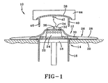
- Fig. 1 shows a first exemplary embodiment of a device according to the invention for folding an airbag of an airbag module, in a side view in partial section;
- Fig. 2 shows a second exemplary embodiment of a device according to the invention for folding an airbag of an airbag module, in a view according to Fig. 1, during a first process step;
- Fig. 3 shows the view according to Fig. 2, in a second process step;
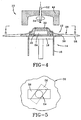
- Fig. 4 shows a third exemplary embodiment of a device for folding an airbag of an airbag module, which is not covered by the invention; and
- Fig. 5 shows a plan view according to Fig. 4, on a larger scale.
- Fig. 1 illustrates a
device 10 for folding an airbag of anairbag module 12, in particular a driver airbag module. Thedevice 10 has areceiver 14 with a substantially vertically arranged cylinder ortube 16 and a piston or die 18 arranged displaceably therein. Constructed around the upper edge (as seen in Fig. 1) of thetube 16 is asupport 20. - The
airbag module 12 is arranged on thereceiver 14. It has abase plate 22 which lies on thepiston 18, and in the centre of thebase plate 22, remote from thepiston 18, there is constructed aportion 24 for arranging or inserting a inflator (not illustrated). Advantageously, instead of theportion 24, the inflator itself may be used with a base plate arranged thereon. Anairbag 26 is secured to thebase plate 22 and includes anouter sheath 28 andrestraining tapes 30 arranged therein. Theairbag 26 is laid out with itsouter sheath 28 over thebase plate 22 and is spread out over thesupport 20. Aportion 32 of theouter sheath 28 of theairbag 26 remote from thebase plate 22 is provided with atab 34 which projects upwards (as seen in Fig. 1) from theouter sheath 28. A through opening 36 is made in thetab 34 approximately in the centre. - Above the tab 34 (as seen in Fig. 1), a
cover 38 in the form of a cap of theairbag module 12 is arranged on thedevice 10. Thecover 38 has downwardly projectingwebs 40 and, in the centre of its underside, ahook 42 which projects downwards (as seen in Fig. 1). Thecover 38 is supported by a holdingdevice 44 that is movable substantially vertically relative to thereceiver 14 of thedevice 10. - With the aid of the
device 10, theairbag 26 of theairbag module 12 can first be stretched out and then folded. To be able to perform these operations, first of all thetab 34 is hooked onto thehook 42 of thecover 38, manually or automatically, at the throughopening 36. Then, thepiston 18 moves in thetube 16, as a result of which thebase plate 22 moves downwards (as seen in Fig. 1). During this relative movement between thereceiver 14 and the holdingdevice 44, theportion 32 of theairbag 26 is pulled away from thebase plate 22, and theouter sheath 28 of theairbag 26 is at the same time stretched out until the restrainingtapes 30 are substantially fully taut. - At the same time, the
tube 16 may be moved upwards and/or thecover 38 with the holdingdevice 44 may be moved downwards until thewebs 40 of thecover 38 are set on the upper rim of thetube 16. Then, thepiston 18 is moved upwards (as seen in Fig. 1) inside thetube 16. During this movement, theairbag 26 is now laid in chaotically arranged folds inside thetube 16 and at the same time pushed into thecover 38 from below. - The through
opening 36 in thetab 34 is constructed such that when theairbag module 12 having theairbag 26 and installed in a vehicle is activated and unfolded, the connection between thetab 34 and thehook 42 is released automatically. Once the connection has been automatically released, theairbag 26 can unfold freely, independently of thecover 38. - Figs. 2 and 3 illustrate a second embodiment of the
device 10, which is shaped in a manner corresponding to thedevice 10 illustrated in Fig. 1 as regards thereceiver 14. - For the
device 10 according to Figs. 2 and 3, the associatedairbag module 12 on thecover 38 and theairbag 26 is, however, slightly modified. Thecover 38 is provided on each of itswebs 40 with a substantially horizontally extendinghole 46. The twoholes 46 lie opposite one another, so that arod 48 may be pushed in manually or automatically. Two throughopenings 50 are made in thetab 34 of theairbag 26, by means of which thetabs 34 may be threaded onto therod 48 when the latter is pushed in. - The connection, made by the
rod 48 and the throughopenings 50, between thecover 38 and theportion 32 of theairbag 26 creates a releasable connection by means of which theportion 32 in thedevice 10 can first be pulled away from thebase plate 22, while it still remains possible for theportion 32 to be released from thecover 38 again once theairbag 26 has been folded. For the purpose of release, all that is necessary is for therod 48 to be withdrawn from the twoholes 46 in thewebs 40 and from the two throughopenings 50 in thetab 34. The connection between thecover 38 and theairbag 26 is hence released again, and theairbag 26 can later on be unfolded in a safety-critical situation, independently of thecover 38. - Fig. 3 illustrates how the
tab 34 of theairbag 26 is secured to thecover 38 with the aid of therod 48 and hence to the holdingdevice 44 while the airbag is being stretched out. Fig. 3 shows the process step during which the restrainingtapes 30 are fully taut. During this process step, theouter sheath 28 of theairbag 26 still forms a peripheral folded layer. This folded layer is moved upwards (as seen in Fig. 3) into the interior of thetube 16 by a subsequent displacement of thetube 16. At the same time, the upper rim of thetube 16 is guided towards thewebs 40 of thecover 38. As a result of a subsequent upward movement of thepiston 18, theairbag 26 is laid in folds and compressed in the interior of thetube 16 and below thecover 38. At the end of the upward movement of thepiston 18, therod 48 is withdrawn from theholes 46, and finally the foldedairbag 26 is pushed into the underside of thecover 38 by thepiston 18. Theairbag module 12 is pre-mounted with its foldedairbag 26 and thecover 38. - Fig. 4 illustrates another example of a
device 10 not forming part of the present invention. The device is shaped in manner corresponding to thedevices 10 illustrated in Figs. 1 to 3 as regards thereceiver 14. As regards the holdingdevice 44, however, nocover 38 is provided in the case of thedevice 10 according to Fig. 4. Instead, the holdingdevice 44 is constructed in a shape that corresponds to the underside of acover 38 of anairbag module 12. - A substantially vertically arranged
pin 52 passes through the centre of the holdingdevice 44, and ahook element 54 is constructed on the underside thereof. Thehook element 54 has twohook wings 56 which are opposite one another and extend substantially horizontally. Anelongate opening 58, below which a fabric layer of the restrainingtapes 30 is also located, is constructed in theouter sheath 28 of theairbag 26 of an associatedairbag module 12. - In the
device 10 illustrated in Figs. 4 and 5 for folding theairbag 26, a releasable connection is made between the holdingdevice 44 and theportion 32 of theairbag 26 in that thepin 52, by means of itshook wings 56 on thehook element 54, is first pushed through theopening 58 in theouter sheath 28 and then turned through an angle of approximately 90°. During this turning movement, thehook wings 56 are pushed underneath theouter sheath 28 in theportion 32. When thereceiver 14 is subsequently moved relative to the holdingdevice 44, theportion 32 is secured to the holdingdevice 44 with the aid of thehook element 54 and is hence pulled away from thebase plate 22 to stretch out theairbag 26. - The procedure of folding the
airbag 26 is performed as illustrated in particular in Fig. 3. At the end of the folding procedure, thepin 52 is again turned through an angle of approximately 90°, as a result of which thehook wings 56 of thehook element 54 are brought into congruence with theelongate opening 58 in theouter sheath 28. Theairbag module 12, together with its foldedairbag 26, can now be moved out of the holdingdevice 44 because the connection between thehook element 54 and theportion 32 of theairbag 26 is then undone again. Theairbag module 12, together with its foldedairbag 26, can be further installed. - In another example of a device for folding an airbag of an airbag module, which is not illustrated, a cover is provided through which a
pin 52 illustrated in Figs. 4 and 5 can be introduced. With the aid ofhook wings 56 on thepin 52, the airbag can then be stretched out underneath the cover. Then thepin 52 is released from the airbag again and withdrawn from the cover. The opening required in the cover is closed for example using an emblem of a vehicle manufacturer. Alternatively or in addition to arotary pin 52, a rotary and/or pivotal hook may also be provided.
Claims (11)
- A process for folding an airbag (26) of an airbag module (12), having the steps of:arranging the airbag (26) and a base plate (22) on a receiver (14) of a folding device (10), with the airbag (26) secured to the base plate (22), and stretching the airbag (26) out,arranging a cover (38) of the airbag module (12) on a holding device (44) of the folding device (10),a first connection element (42, 48) being arranged on the cover (38), a second connection element (34) comprising at least one opening (36, 50) being provided on a portion (32) of the airbag (26) remote from the base plate (22)introducing the first connection element in the form of a rod (48) or a hook (42) into the at least one opening (36, 50) of the second connection element (34) thereby securing the portion (32) of the airbag (26) to the cover (38) of the airbag module (12), andstretching out the airbag (26) by pulling the secured portion (32) by means of a movement of the holding device (44) relative to the receiver (14), the receiver (14) having a substantially vertically arranged cylinder or tube (16) and a piston or die (18) arranged displaceably therein, the holding device (44) being movable substantially vertically relative to the receiver (14).
- A process for folding an airbag according to Claim 1, characterised by the step of arranging an inflator connected to the base plate (22) on the receiver (14) before the step of stretching out the airbag (26).
- A process for folding an airbag according to Claim 1 or 2, characterised by the step of releasing the connection at the end of the step or after the step of stretching out the airbag (26).
- A process for folding an airbag according to Claim 3, characterised by the step of withdrawing a first connection element (48) between the airbag (26) and the holding device (44).
- A folding device which is adapted to perform the process for folding an airbag according to one of Claims 1 to 4.
- An airbag module (12) having a base plate (22) and an airbag (26) secured to the latter, wherein
the airbag (26) is adapted to be releasably securable to a first connection element (42, 48) arranged on a cover (38) arranged on a folding device (10) by a second connection element (34, 36, 50) being provided on a portion (32) of the airbag (26) remote from the base plate (22),
this second connection element being shaped such that by means of the first and second connection elements the portion (32) of the airbag (26) is to be pulled relative to the base plate (22) and hence stretched out, and
the second connection element is constructed with at least one opening (36, 50) made in the airbag (26) into which a first connection element in the form of a rod (48) or a hook (42) may be introduced. - An airbag module according to Claim 6, characterised in that an inflator is connected to the base plate (22) before the airbag (26) is stretched out.
- An airbag module according to one of Claims 6 to 7, characterised in that a cover (38) is provided on which the first connection element (42, 48) is arranged
- An airbag module according to Claim 8, characterised in that the first connection element (42, 48) is guided or arranged as one piece on the cover (38).
- An airbag module according to one of Claims 6 to 9, characterised in that the connection between the first and the second connection element is made releasable such that it is released automatically when the airbag (26) is activated
- An airbag module according to Claim 10, characterised in that on activation a hook (42), as the first connection element, is torn out of an opening (36), as the second connection element.
Applications Claiming Priority (2)
| Application Number | Priority Date | Filing Date | Title |
|---|---|---|---|
| DE10204643 | 2002-02-05 | ||
| DE10204643A DE10204643C1 (en) | 2002-02-05 | 2002-02-05 | Method and device for folding an airbag module gas bag |
Publications (2)
| Publication Number | Publication Date |
|---|---|
| EP1332928A1 EP1332928A1 (en) | 2003-08-06 |
| EP1332928B1 true EP1332928B1 (en) | 2007-10-31 |
Family
ID=7713699
Family Applications (1)
| Application Number | Title | Priority Date | Filing Date |
|---|---|---|---|
| EP03002529A Expired - Lifetime EP1332928B1 (en) | 2002-02-05 | 2003-02-05 | Method of folding an airbag |
Country Status (5)
| Country | Link |
|---|---|
| US (1) | US6779813B2 (en) |
| EP (1) | EP1332928B1 (en) |
| JP (1) | JP2003237513A (en) |
| KR (1) | KR100524848B1 (en) |
| DE (2) | DE10204643C1 (en) |
Families Citing this family (16)
| Publication number | Priority date | Publication date | Assignee | Title |
|---|---|---|---|---|
| US6789819B1 (en) * | 2003-03-20 | 2004-09-14 | Key Safety Systems, Inc. | Sensor for monitoring airbag deployment |
| US6951532B2 (en) * | 2003-05-09 | 2005-10-04 | Key Safety Systems, Inc. | Method of folding an airbag containing sensor tapes integrated within the airbag |
| DE102005013010A1 (en) * | 2004-12-02 | 2006-06-08 | Trw Automotive Safety Systems Gmbh & Co. Kg | Apparatus and method for folding a gas bag |
| US7980590B2 (en) | 2008-03-19 | 2011-07-19 | Amsafe, Inc. | Inflatable personal restraint systems having web-mounted inflators and associated methods of use and manufacture |
| US7665761B1 (en) | 2008-03-27 | 2010-02-23 | Amsafe, Inc. | Inflatable personal restraint systems and associated methods of use and manufacture |
| US8469397B2 (en) | 2011-04-13 | 2013-06-25 | Amsafe, Inc. | Stitch patterns for restraint-mounted airbags and associated systems and methods |
| KR101737528B1 (en) * | 2011-07-15 | 2017-05-19 | 현대모비스 주식회사 | Apparatus for folding a driver airbag cushion and method for folding the driver airbag cushion |
| US8439398B2 (en) | 2011-07-29 | 2013-05-14 | Amsafe, Inc. | Inflator connectors for inflatable personal restraints and associated systems and methods |
| US9511866B2 (en) | 2012-03-19 | 2016-12-06 | Amsafe, Inc. | Structure mounted airbag assemblies and associated systems and methods |
| US8523220B1 (en) | 2012-03-19 | 2013-09-03 | Amsafe, Inc. | Structure mounted airbag assemblies and associated systems and methods |
| US9352839B2 (en) | 2014-10-02 | 2016-05-31 | Amsafe, Inc. | Active positioning airbag assembly and associated systems and methods |
| US9944245B2 (en) | 2015-03-28 | 2018-04-17 | Amsafe, Inc. | Extending pass-through airbag occupant restraint systems, and associated systems and methods |
| SG11201708221UA (en) | 2015-04-11 | 2017-11-29 | Amsafe Inc | Active airbag vent system |
| KR102457263B1 (en) * | 2015-12-10 | 2022-10-20 | 현대모비스 주식회사 | Apparatus for assembling a passenger air bag and method for assembling the passenger air bag |
| US10604259B2 (en) | 2016-01-20 | 2020-03-31 | Amsafe, Inc. | Occupant restraint systems having extending restraints, and associated systems and methods |
| DE102018102869A1 (en) * | 2018-02-08 | 2019-08-08 | Dalphi Metal Espana, S.A. | Airbag module and method for producing an airbag module |
Citations (4)
| Publication number | Priority date | Publication date | Assignee | Title |
|---|---|---|---|---|
| US5360387A (en) * | 1993-02-03 | 1994-11-01 | Jamal Saklou | Bag folding system |
| EP0712760A1 (en) * | 1994-11-15 | 1996-05-22 | TRW Occupant Restraint Systems GmbH | Folding method of an air bag for a vehicle occupant restraint system, device for performing this method and air bag so obtained |
| DE19535564A1 (en) * | 1995-09-12 | 1997-03-13 | Petri Ag | Method and device for folding an airbag for an airbag module |
| EP0825072A1 (en) * | 1996-08-19 | 1998-02-25 | TAKATA (EUROPE) VEHICLE SAFETY TECHNOLOGY GmbH | Method and device to recess an airbag folded as a package in an airbag device housing |
Family Cites Families (9)
| Publication number | Priority date | Publication date | Assignee | Title |
|---|---|---|---|---|
| DE19536625C2 (en) * | 1995-09-22 | 2003-08-14 | Takata Petri Ag | Method for folding an airbag and device for carrying out the folding |
| DE19648654A1 (en) * | 1996-11-15 | 1998-05-20 | Petri Ag | Airbag for an airbag module and method and device for folding an airbag |
| DE29811042U1 (en) * | 1998-06-19 | 1999-02-11 | Trw Automotive Safety Sys Gmbh | Airbag folding device |
| DE19827725A1 (en) | 1998-06-22 | 1999-12-23 | Delphi Automotive Systems Gmbh | Method and device for folding an inflatable air bag |
| DE19831613A1 (en) | 1998-07-14 | 2000-01-20 | Delphi Automotive Systems Gmbh | Method and device for folding an inflatable air bag |
| BR9912149A (en) | 1998-09-14 | 2001-09-25 | Breed Automotive Tech | Process and apparatus for folding an airbag |
| DE19845721A1 (en) | 1998-10-05 | 2000-04-06 | Takata Europ Gmbh | Procedure for folding an airbag |
| GB2371025B (en) | 2001-01-12 | 2004-05-12 | Autoliv Dev | Improvements in or relating to a method of and apparatus for folding an air-bag |
| US6588179B2 (en) * | 2001-08-31 | 2003-07-08 | Delphi Technologies, Inc. | Method and apparatus for packaging an airbag |
-
2002
- 2002-02-05 DE DE10204643A patent/DE10204643C1/en not_active Expired - Fee Related
- 2002-08-07 US US10/212,807 patent/US6779813B2/en not_active Expired - Lifetime
-
2003
- 2003-02-04 KR KR10-2003-0006696A patent/KR100524848B1/en not_active Expired - Fee Related
- 2003-02-05 DE DE60317121T patent/DE60317121T2/en not_active Expired - Fee Related
- 2003-02-05 JP JP2003028463A patent/JP2003237513A/en not_active Withdrawn
- 2003-02-05 EP EP03002529A patent/EP1332928B1/en not_active Expired - Lifetime
Patent Citations (4)
| Publication number | Priority date | Publication date | Assignee | Title |
|---|---|---|---|---|
| US5360387A (en) * | 1993-02-03 | 1994-11-01 | Jamal Saklou | Bag folding system |
| EP0712760A1 (en) * | 1994-11-15 | 1996-05-22 | TRW Occupant Restraint Systems GmbH | Folding method of an air bag for a vehicle occupant restraint system, device for performing this method and air bag so obtained |
| DE19535564A1 (en) * | 1995-09-12 | 1997-03-13 | Petri Ag | Method and device for folding an airbag for an airbag module |
| EP0825072A1 (en) * | 1996-08-19 | 1998-02-25 | TAKATA (EUROPE) VEHICLE SAFETY TECHNOLOGY GmbH | Method and device to recess an airbag folded as a package in an airbag device housing |
Also Published As
| Publication number | Publication date |
|---|---|
| DE60317121D1 (en) | 2007-12-13 |
| JP2003237513A (en) | 2003-08-27 |
| DE10204643C1 (en) | 2003-10-16 |
| KR20030066442A (en) | 2003-08-09 |
| EP1332928A1 (en) | 2003-08-06 |
| US6779813B2 (en) | 2004-08-24 |
| DE60317121T2 (en) | 2008-08-14 |
| US20030146613A1 (en) | 2003-08-07 |
| KR100524848B1 (en) | 2005-10-28 |
Similar Documents
| Publication | Publication Date | Title |
|---|---|---|
| EP1332928A1 (en) | Method of folding an airbag | |
| JP3036890U (en) | Airbag module assembly and airbag housing | |
| JP4473274B2 (en) | Airbag structure | |
| JP2009045949A (en) | Air bag device | |
| AU2006256054B2 (en) | Airbag device | |
| US5795284A (en) | Method of and device for folding a gas bag of a vehicle occupant restraint system | |
| JP4113356B2 (en) | Airbag folding method and apparatus | |
| EP2519426A1 (en) | Air bag having a slit in a border region | |
| KR101301135B1 (en) | Method of assembling airbag device and airbag device | |
| JP4836494B2 (en) | Airbag device | |
| KR19980703232A (en) | Airbag device, how to fold airbags and airbag folding device | |
| JP3723732B2 (en) | Air bag, air bag device, and air bag folding method | |
| KR101301137B1 (en) | Folding device and folding method for airbag | |
| US5800328A (en) | Method of and device for folding a gas bag of a vehicle occupant restraint system | |
| JP3039624U (en) | Airbag module with assembly / attachment means | |
| EP1499519A2 (en) | Airbag tie back | |
| JP2011136697A (en) | Airbag device | |
| EP1772255B1 (en) | Airbag folding apparatus and method | |
| JPH07117603A (en) | Sewing method for suspension cloth of air bag and sewing machine therefor | |
| JP2003104152A (en) | Airbag folding method and system | |
| JP2007015542A5 (en) |
Legal Events
| Date | Code | Title | Description |
|---|---|---|---|
| PUAI | Public reference made under article 153(3) epc to a published international application that has entered the european phase |
Free format text: ORIGINAL CODE: 0009012 |
|
| AK | Designated contracting states |
Designated state(s): AT BE BG CH CY CZ DE DK EE ES FI FR GB GR HU IE IT LI LU MC NL PT SE SI SK TR |
|
| AX | Request for extension of the european patent |
Extension state: AL LT LV MK RO |
|
| 17P | Request for examination filed |
Effective date: 20040116 |
|
| AKX | Designation fees paid |
Designated state(s): DE FR GB IT |
|
| 17Q | First examination report despatched |
Effective date: 20041124 |
|
| RAP1 | Party data changed (applicant data changed or rights of an application transferred) |
Owner name: KEY SAFETY SYSTEMS, INC. |
|
| 17Q | First examination report despatched |
Effective date: 20041124 |
|
| GRAP | Despatch of communication of intention to grant a patent |
Free format text: ORIGINAL CODE: EPIDOSNIGR1 |
|
| GRAS | Grant fee paid |
Free format text: ORIGINAL CODE: EPIDOSNIGR3 |
|
| GRAA | (expected) grant |
Free format text: ORIGINAL CODE: 0009210 |
|
| AK | Designated contracting states |
Kind code of ref document: B1 Designated state(s): DE FR GB IT |
|
| REG | Reference to a national code |
Ref country code: GB Ref legal event code: FG4D |
|
| REF | Corresponds to: |
Ref document number: 60317121 Country of ref document: DE Date of ref document: 20071213 Kind code of ref document: P |
|
| PGFP | Annual fee paid to national office [announced via postgrant information from national office to epo] |
Ref country code: DE Payment date: 20080229 Year of fee payment: 6 |
|
| ET | Fr: translation filed | ||
| PLBE | No opposition filed within time limit |
Free format text: ORIGINAL CODE: 0009261 |
|
| STAA | Information on the status of an ep patent application or granted ep patent |
Free format text: STATUS: NO OPPOSITION FILED WITHIN TIME LIMIT |
|
| 26N | No opposition filed |
Effective date: 20080801 |
|
| PGFP | Annual fee paid to national office [announced via postgrant information from national office to epo] |
Ref country code: GB Payment date: 20090106 Year of fee payment: 7 |
|
| PGFP | Annual fee paid to national office [announced via postgrant information from national office to epo] |
Ref country code: FR Payment date: 20090206 Year of fee payment: 7 |
|
| PG25 | Lapsed in a contracting state [announced via postgrant information from national office to epo] |
Ref country code: DE Free format text: LAPSE BECAUSE OF NON-PAYMENT OF DUE FEES Effective date: 20090901 |
|
| GBPC | Gb: european patent ceased through non-payment of renewal fee |
Effective date: 20100205 |
|
| REG | Reference to a national code |
Ref country code: FR Ref legal event code: ST Effective date: 20101029 |
|
| PG25 | Lapsed in a contracting state [announced via postgrant information from national office to epo] |
Ref country code: FR Free format text: LAPSE BECAUSE OF NON-PAYMENT OF DUE FEES Effective date: 20100301 |
|
| PG25 | Lapsed in a contracting state [announced via postgrant information from national office to epo] |
Ref country code: IT Free format text: LAPSE BECAUSE OF NON-PAYMENT OF DUE FEES Effective date: 20080229 |
|
| PG25 | Lapsed in a contracting state [announced via postgrant information from national office to epo] |
Ref country code: GB Free format text: LAPSE BECAUSE OF NON-PAYMENT OF DUE FEES Effective date: 20100205 |