EP1332927A2 - Vehicular wireless transmission control assembly - Google Patents
Vehicular wireless transmission control assembly Download PDFInfo
- Publication number
- EP1332927A2 EP1332927A2 EP03002036A EP03002036A EP1332927A2 EP 1332927 A2 EP1332927 A2 EP 1332927A2 EP 03002036 A EP03002036 A EP 03002036A EP 03002036 A EP03002036 A EP 03002036A EP 1332927 A2 EP1332927 A2 EP 1332927A2
- Authority
- EP
- European Patent Office
- Prior art keywords
- vehicular
- wireless transmission
- transmission control
- control assembly
- assembly according
- Prior art date
- Legal status (The legal status is an assumption and is not a legal conclusion. Google has not performed a legal analysis and makes no representation as to the accuracy of the status listed.)
- Withdrawn
Links
Images


Classifications
-
- B—PERFORMING OPERATIONS; TRANSPORTING
- B60—VEHICLES IN GENERAL
- B60R—VEHICLES, VEHICLE FITTINGS, OR VEHICLE PARTS, NOT OTHERWISE PROVIDED FOR
- B60R16/00—Electric or fluid circuits specially adapted for vehicles and not otherwise provided for; Arrangement of elements of electric or fluid circuits specially adapted for vehicles and not otherwise provided for
- B60R16/02—Electric or fluid circuits specially adapted for vehicles and not otherwise provided for; Arrangement of elements of electric or fluid circuits specially adapted for vehicles and not otherwise provided for electric constitutive elements
- B60R16/03—Electric or fluid circuits specially adapted for vehicles and not otherwise provided for; Arrangement of elements of electric or fluid circuits specially adapted for vehicles and not otherwise provided for electric constitutive elements for supply of electrical power to vehicle subsystems or for
- B60R16/0315—Electric or fluid circuits specially adapted for vehicles and not otherwise provided for; Arrangement of elements of electric or fluid circuits specially adapted for vehicles and not otherwise provided for electric constitutive elements for supply of electrical power to vehicle subsystems or for using multiplexing techniques
Definitions
- the present invention relates to a wireless transmission control assembly, and more particular to a wireless transmission control assembly for adjusting a view range of a vehicular monitoring device according to a vehicular status indicator.
- the rearview mirror can be adjusted manually or automatically by pushing buttons. After the adjustment of rearview mirrors is done, the view angle of each rearview mirror seen by the driver is constant, and it is difficult and also dangerous for the driver to further change the view angles while driving.
- some deluxe cars are equipped with a view-angle adjustable rearview mirror.
- the view angle of the rearview mirror can be automatically adjusted in order to avoid any blind spot. For example, when the vehicle is turning right, it is desirable that the driver clearly sees the right lane by rotating the exterior rearview mirror at the right side of the vehicle outwards.
- an object of the present invention is to provide a control assembly, which can be easily incorporated into the layout of a car to automatically adjust the view angle of the rearview mirror.
- a first aspect of the present invention relates to a wireless transmission control assembly for used with a vehicular monitoring device and a vehicular status indicator.
- the assembly comprises a sensing device in communication with the vehicular status indicator, asserting a control signal in response to an enabled operation of the vehicular status indicator; a wireless signal transmitter in communication with the sensing device, transforming the control signal into a wireless transmission control signal, and outputting the wireless transmission control signal; a wireless signal receiver receiving and recovering the wireless transmission control signal into the control signal; and a control device in communication with the wireless signal receiver and the vehicular monitoring device, having the vehicular monitoring device perform a view-range adjusting operation in response to the control signal.
- the sensing device and the wireless signal transmitter are disposed adjacent to the vehicular status indicator.
- the vehicular status indicator is a turning-direction indicator light
- the sensing device and the wireless signal transmitter are preferably disposed in the trunk of a vehicle.
- the vehicular status indicator can also be selected from a group consisting of an indicator-light switch, an electronic compass, a global positioning system (GPS), a telematics system, an attitude indicator, a vehicle stability control system, and a yaw sensor.
- GPS global positioning system
- the wireless signal receiver and the control device are disposed adjacent to the vehicular monitoring device.
- the vehicular monitoring device may include a rearview mirror, a camera, and/or a display.
- the view-range adjusting operation of the vehicular monitoring device is a rotating operation.
- the vehicular monitoring device is rotated from an initial position toward a working position in response to the assertion of the control signal, and rotated back to the initial position in response to the suspension of the control signal.
- the view-range adjusting operation of the vehicular monitoring device is disabled when two different control signals are received by the control device at the same time.
- the view-range adjusting operation of the vehicular monitoring device is a zooming operation.
- the wireless signal transmitter is in communication with the sensing device via a vehicular digital bus
- the control device is in communication with the wireless signal receiver via the vehicular digital bus.
- the vehicular digital bus for example, is a controller area network (CAN) bus or a vehicle area network (VAN) bus.
- the view-range adjusting operation of the vehicular monitoring device is performed at a rate correlating to a driving speed of the vehicle.
- the wireless transmission control assembly includes two sensing devices 12, two wireless signal transmitters 13, a wireless signal receiver 14 and a control device 15.
- the two sensing devices 12 are disposed adjacent to the rear left- and right-turn indicator lights 10, respectively, and connected between the main circuit 1 of the vehicle and the indicator lights 10.
- the two wireless signal transmitters 13 are connected to the two sensing devices, respectively, and thus preferably also disposed near the indicator lights 10.
- the sensing devices 12 and wireless signal transmitters 13 can be placed in the trunk of the vehicle.
- the wireless signal receiver 14 and the control device 15 are disposed adjacent to one of the rearview mirrors 16, e.g. the rearview mirror at the driver's side.
- the sensing device 12 at the right side will also detect the enabled operation of the indicator light 10 so as to assert a control signal.
- the wireless signal transmitter 13 once receiving the control signal, transforms the control signal into a wireless transmittable form, e.g. a radio frequency (RF) signal or a microwave signal, and outputs the control signal indicative of the turning operation of the vehicle.
- the wireless transmitted control signal is received by the wireless signal receiver 14, and demodulated into the control signal to be read by the control device 15.
- the control device 15 turns the rearview mirror 16 at the right side outwards, i.e. counterclockwise, to enlarge the view range at the right side.
- both of the rearview mirrors 16 can be turned counterclockwise to have even larger view range at the right side.
- the rearview mirror is rotated from an initial position toward a working position in response to the assertion of the control signal, as mentioned above, and kept at the working position until the control signal is suspended.
- the indicator-light switch 11 should be automatically or manually switched off so as to turn off the indicator light 10 at the right side.
- the assertion of the control signal stops, and thus the control device 15 has the rearview mirror(s) 16 rotated back to the initial position.
- the view-range adjusting operation for the rearview mirror(s) is disabled. In other words, the rearview mirrors are maintained at the initial position.
- the similar operation can be performed for the case when the driver would like to turn the vehicle left.
- the left-side rearview mirror 16 or both the rearview mirrors 16 are rotated clockwise to enlarge the view range at the left side in response to the control signal asserted by the left-side sensing device 12 when the left-turn indicator light 10 is turned on.
- the control assembly for automatically adjusting the view range of the rearview mirror while the vehicle is turning can be easily attached to the layout of the vehicle.
- the sensing devices and the wireless signal transmitters can be mounted in the trunk, and the wireless receiver and the control device can be mounted near the console. Therefore, the control assembly of the invention can be mounted without moving the furniture and altering the main circuit of the vehicle.
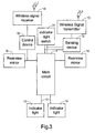
- Fig. 3 is a schematic circuit block diagram showing a simplified layout of a vehicle associated with automatic view-range adjustment according to another preferred embodiment of the present invention.
- the main circuit 1 is a vehicular digital bus such as a controller area network (CAN) bus or a vehicle area network (VAN) bus.
- the sensing device 12 is connected to the vehicular digital bus 1.
- CAN controller area network
- VAN vehicle area network
- the control device 15 When the driver intends to turn the vehicle right, for example, he should manipulate the indicator light switch 11, and a digital encoded signal is outputted to the vehicular digital bus 1.
- the sensing device 12 while detecting the digital encoded signal from the vehicular digital bus 1, asserts a control signal indicative of the right turn information to the wireless signal transmitter 13.
- the wireless signal transmitter 13 then transforms and outputs the control signal in a wireless transmission format.
- the wireless transmitted control signal is received by the wireless signal receiver 14, and demodulated into the control signal to be read by the control device 15.
- the control device 15 turns the rearview mirror 16 at the right side outwards, i.e. counterclockwise, to enlarge the view range at the right side.
- both of the rearview mirrors 16 can be turned counterclockwise to have even larger view range at the right side.
- the sensing device 12 can detect the enabled operation of the indicator-light switch 11 via the vehicular digital bus 1, the sensing device 12 can be mounted at any position advantageous to mounting work.
- the relative positions of the wireless signal transmitter 13 and the wireless signal receiver 14 should be suitable for the wireless transmission.
- the indicator lights and the indicator light switch are exemplified as vehicular status indicators for determining whether the view range of the rearview mirror is to be adjusted.
- vehicular status indicators can also be used to realize the current or coming action of the vehicle so that the view range of the rearview mirror can be adjusted simultaneously or in advance if necessary.
- the vehicular status indicators for example, include an indicator-light switch, an electronic compass, a global positioning system (GPS), a telematics system, an attitude indicator, a vehicle stability control system, and a yaw sensor.
- Some of the output signals indicate the turning operation of the vehicle, some indicate the slope change of the vehicle, and others indicate the speed change of the vehicle.
- the rearview mirror is preferably turned downwards in response to the control signal.
- the two rearview mirrors are both rotated outwards for facilitating the overtaking operation.
- the driver can also monitor the exterior situation via other vehicular monitoring devices, e.g. CCD (charge coupled device) or CMOS (complementary metal oxide semiconductor) cameras, backup radars and displays such as liquid crystal displays.
- CCD charge coupled device
- CMOS complementary metal oxide semiconductor
- the rearview mirrors, cameras and backup radars can be rotated in response to the control signal to change the view range.
- the displays can change the view range by a zoom in/out operation.
- the view-range adjusting operation of the vehicular monitoring device is performed at a rate correlating to a driving speed of the vehicle.
- the faster the vehicle is driven the faster the motor speed for rotating rearview mirrors, cameras and/or backup radars, and the zooming speed of the displays.
Landscapes
- Engineering & Computer Science (AREA)
- Mechanical Engineering (AREA)
- Rear-View Mirror Devices That Are Mounted On The Exterior Of The Vehicle (AREA)
- Selective Calling Equipment (AREA)
- Fittings On The Vehicle Exterior For Carrying Loads, And Devices For Holding Or Mounting Articles (AREA)
Abstract
Description
Claims (13)
- A wireless transmission control assembly for used with a vehicular monitoring device and a vehicular status indicator, comprising:a sensing device in communication with the vehicular status indicator, asserting a control signal in response to an enabled operation of the vehicular status indicator;a wireless signal transmitter in communication with the sensing device, transforming the control signal into a wireless transmission control signal, and outputting the wireless transmission control signal;a wireless signal receiver receiving and recovering the wireless transmission control signal into the control signal; anda control device in communication with the wireless signal receiver and the vehicular monitoring device, having the vehicular monitoring device perform a view-range adjusting operation in response to the control signal.
- The wireless transmission control assembly according to claim 1, characterized in that the sensing device and the wireless signal transmitter are disposed adjacent to the vehicular status indicator.
- The wireless transmission control assembly according to claim 2, characterized in that the vehicular status indicator is a turning-direction indicator light, and the sensing device and the wireless signal transmitter are disposed in the trunk of a vehicle.
- The wireless transmission control assembly according to claim 2, characterized in that the vehicular status indicator is a member selected from a group consisting of an indicator-light switch, an electronic compass, a global positioning system (GPS), a telematics system, an attitude indicator, a vehicle stability control system, and a yaw sensor.
- The wireless transmission control assembly according to claim 1, characterized in that the wireless signal receiver and the control device are disposed adjacent to the vehicular monitoring device.
- The wireless transmission control assembly according to claim 1, characterized in that the vehicular monitoring device includes a rearview mirror, a camera, and/or a display.
- The wireless transmission control assembly according to claim 1, characterized in that the view-range adjusting operation of the vehicular monitoring device is a rotating operation.
- The wireless transmission control assembly according to claim 7, characterized in that the vehicular monitoring device is rotated from an initial position toward a working position in response to the assertion of the control signal, and rotated back to the initial position in response to the suspension of the control signal.
- The wireless transmission control assembly according to claim 1, characterized in that the view-range adjusting operation of the vehicular monitoring device is disabled when two different control signals are received by the control device at the same time.
- The wireless transmission control assembly according to claim 1, characterized in that the view-range adjusting operation of the vehicular monitoring device is a zooming operation.
- The wireless transmission control assembly according to claim 1, characterized in that the wireless signal transmitter is in communication with the sensing device via a vehicular digital bus, and the control device is in communication with the wireless signal receiver via the vehicular digital bus.
- The wireless transmission control assembly according to claim 11, characterized in that the vehicular digital bus is a controller area network (CAN) bus or a vehicle area network (VAN) bus.
- The wireless transmission control assembly according to claim 1, characterized in that the view-range adjusting operation of the vehicular monitoring device is performed at a rate correlating to a driving speed of the vehicle.
Applications Claiming Priority (2)
| Application Number | Priority Date | Filing Date | Title |
|---|---|---|---|
| CN02103109 | 2002-01-30 | ||
| CN02103109A CN1412724A (en) | 2002-01-30 | 2002-01-30 | Wireless Transmission Control Module |
Publications (2)
| Publication Number | Publication Date |
|---|---|
| EP1332927A2 true EP1332927A2 (en) | 2003-08-06 |
| EP1332927A3 EP1332927A3 (en) | 2004-10-20 |
Family
ID=4739812
Family Applications (1)
| Application Number | Title | Priority Date | Filing Date |
|---|---|---|---|
| EP03002036A Withdrawn EP1332927A3 (en) | 2002-01-30 | 2003-01-28 | Vehicular wireless transmission control assembly |
Country Status (4)
| Country | Link |
|---|---|
| US (1) | US20030141964A1 (en) |
| EP (1) | EP1332927A3 (en) |
| JP (1) | JP2003267136A (en) |
| CN (1) | CN1412724A (en) |
Families Citing this family (13)
| Publication number | Priority date | Publication date | Assignee | Title |
|---|---|---|---|---|
| TWM303142U (en) * | 2006-04-19 | 2006-12-21 | Jeng-Chiun Chen | Wireless signal light module for car |
| US10013815B2 (en) * | 2006-12-13 | 2018-07-03 | Crown Equipment Corporation | Information system for industrial vehicles |
| CA2909832C (en) | 2006-12-13 | 2018-05-01 | Crown Equipment Corporation | Fleet management system |
| US11225404B2 (en) | 2006-12-13 | 2022-01-18 | Crown Equipment Corporation | Information system for industrial vehicles |
| US10600256B2 (en) | 2006-12-13 | 2020-03-24 | Crown Equipment Corporation | Impact sensing usable with fleet management system |
| US9984341B2 (en) * | 2006-12-13 | 2018-05-29 | Crown Equipment Corporation | Information system for industrial vehicles including cyclical recurring vehicle information message |
| US8046023B2 (en) * | 2008-03-07 | 2011-10-25 | Sony Ericsson Mobile Communications Ab | Mobile communication device with direction indicator |
| CN102483836B (en) | 2009-08-12 | 2016-03-16 | 克朗设备公司 | For the infosystem of industrial vehicle |
| CA2771170C (en) | 2009-09-01 | 2019-11-05 | Crown Equipment Corporation | Information system for industrial vehicles including cyclical recurring vehicle information message |
| US20120022749A1 (en) * | 2010-07-22 | 2012-01-26 | Thomas Clegg | Apparatus and methods for eliminating or reducing blind spots in vehicle mirror and camera systems |
| US8941482B1 (en) * | 2011-06-23 | 2015-01-27 | BenJoaquin Tomas Gouverneur | Automating turn indication systems |
| CN103513803A (en) * | 2012-06-25 | 2014-01-15 | 台景达科技股份有限公司 | Display device with wireless transmission function and wireless transmission method of display device |
| CN108275073A (en) * | 2018-03-02 | 2018-07-13 | 广东东箭汽车科技股份有限公司 | A kind of automobile lane change auxiliary system and method |
Family Cites Families (23)
| Publication number | Priority date | Publication date | Assignee | Title |
|---|---|---|---|---|
| JPS6146743A (en) * | 1984-08-13 | 1986-03-07 | Nissan Motor Co Ltd | Position adjusting device for motor appliance to be mounted on car |
| US4679158A (en) * | 1985-03-21 | 1987-07-07 | Tate William J | Automatic mirror rotating system |
| DK604786D0 (en) * | 1986-12-16 | 1986-12-16 | Jensen Kaj Berg | SELF-CONTROL SIDE MIRROR |
| JPH03224838A (en) * | 1990-01-30 | 1991-10-03 | Nissan Motor Co Ltd | Side mirror for vehicle |
| JPH04201749A (en) * | 1990-11-30 | 1992-07-22 | Toshiba Corp | Rear view mirror device |
| JPH0538984A (en) * | 1991-08-06 | 1993-02-19 | Honda Access:Kk | Cordless mobile telephone |
| US6498620B2 (en) * | 1993-02-26 | 2002-12-24 | Donnelly Corporation | Vision system for a vehicle including an image capture device and a display system having a long focal length |
| JPH0732942A (en) * | 1993-07-15 | 1995-02-03 | Yoichi Hattori | Vision field regulating device of electric fender mirror |
| JPH0858470A (en) * | 1994-08-24 | 1996-03-05 | Alpine Electron Inc | Rear view confirmation device |
| JPH0939661A (en) * | 1995-07-31 | 1997-02-10 | Mitsubishi Automob Eng Co Ltd | Electric mirror device |
| DE19530727B4 (en) * | 1995-08-18 | 2012-09-20 | Kiekert Ag | Method for operating a control system for controlling motor vehicle components |
| JPH09204323A (en) * | 1996-01-26 | 1997-08-05 | Nippon Seiki Co Ltd | Vehicle information transmission device |
| JPH1024801A (en) * | 1996-07-10 | 1998-01-27 | Nec Eng Ltd | In-vehicle side confirmation device |
| US5905433A (en) * | 1996-11-25 | 1999-05-18 | Highwaymaster Communications, Inc. | Trailer communications system |
| DE19924301A1 (en) * | 1999-05-27 | 2000-12-21 | Mekra Lang Gmbh & Co Kg | Control system for electrically operated functional units in motor vehicles |
| DE10000215A1 (en) * | 2000-01-05 | 2001-07-12 | Bosch Gmbh Robert | Device for adjusting a rear-view mirror for a motor vehicle |
| JP2001277952A (en) * | 2000-03-29 | 2001-10-10 | Tokai Rika Co Ltd | Vehicular communication system and vehicular accessories operating system using the vehicular communication system |
| DE10016222A1 (en) * | 2000-03-31 | 2001-10-31 | Volkswagen Ag | Electrical adjustment of outside mirror of motor vehicle when changing lanes based on angle at which change is made |
| JP2001315578A (en) * | 2000-05-10 | 2001-11-13 | Ichikoh Ind Ltd | Side mirror device for connected vehicles |
| WO2001085496A1 (en) * | 2000-05-12 | 2001-11-15 | Kabushiki Kaisha Toyota Jidoshokki | Vehicle backing support apparatus |
| JP4341151B2 (en) * | 2000-08-03 | 2009-10-07 | 株式会社日本自動車部品総合研究所 | In-vehicle wireless communication system |
| JP3084021U (en) * | 2001-08-09 | 2002-02-28 | 峰鼎電子股▲ふん▼有限公司 | Wireless reverse monitoring system for automobiles |
| JP3870779B2 (en) * | 2001-12-20 | 2007-01-24 | 株式会社デンソー | Car monitoring system |
-
2002
- 2002-01-30 CN CN02103109A patent/CN1412724A/en active Pending
-
2003
- 2003-01-28 US US10/352,529 patent/US20030141964A1/en not_active Abandoned
- 2003-01-28 EP EP03002036A patent/EP1332927A3/en not_active Withdrawn
- 2003-01-29 JP JP2003020314A patent/JP2003267136A/en active Pending
Also Published As
| Publication number | Publication date |
|---|---|
| EP1332927A3 (en) | 2004-10-20 |
| US20030141964A1 (en) | 2003-07-31 |
| JP2003267136A (en) | 2003-09-25 |
| CN1412724A (en) | 2003-04-23 |
Similar Documents
| Publication | Publication Date | Title |
|---|---|---|
| US8886401B2 (en) | Driver assistance system for a vehicle | |
| EP3378722B1 (en) | Drive assistance device and drive assistance method, and moving body | |
| EP1332927A2 (en) | Vehicular wireless transmission control assembly | |
| US9802486B2 (en) | Interior display systems and methods | |
| US10346689B2 (en) | Apparatus and method for connecting a mobile device camera | |
| US7012510B2 (en) | Device and method for adjusting view range of vehicular monitoring device | |
| CN102667887A (en) | Portable communication tool, driver assistance system comprising a portable communication tool, and method for aiding a driver when operating a vehicle | |
| EP1338473A2 (en) | Device and method for adjusting view range of vehicular monitoring device | |
| CN111655541A (en) | Driver assistance systems for industrial vehicles | |
| CN107207012A (en) | Driver assistance system for motor vehicle | |
| WO2009002518A2 (en) | A mirror system for a trucking rig having a tractor and an articulated trailer | |
| US20040212676A1 (en) | Optical detection system for vehicles | |
| US20030191569A1 (en) | Vehicular monitor actuating device and method | |
| CN104553985B (en) | Automobile steering auxiliary system | |
| KR20120044752A (en) | A car without side-mirror and a system operating the same | |
| CN205098052U (en) | Car blind spot monitoring and warning device | |
| US20210031686A1 (en) | Vehicular back-up camera system | |
| JP3084469U (en) | Operation image display system | |
| KR20180090521A (en) | Apparatus Preventing camera being robbed of Camera Monitor System For Vehicle and Preventing Method Using it | |
| EP1638814A1 (en) | Proximity sensing system | |
| JP3231104U (en) | Imaging equipment for mobile vehicles compatible with radar equipment | |
| JP2020006733A (en) | Dimmer glass control device for vehicle | |
| KR100971453B1 (en) | Car rearview system | |
| HK1167920A (en) | Data processing system and method for providing at least one driver assistance function |
Legal Events
| Date | Code | Title | Description |
|---|---|---|---|
| PUAI | Public reference made under article 153(3) epc to a published international application that has entered the european phase |
Free format text: ORIGINAL CODE: 0009012 |
|
| AK | Designated contracting states |
Designated state(s): AT BE BG CH CY CZ DE DK EE ES FI FR GB GR HU IE IT LI LU MC NL PT SE SI SK TR |
|
| AX | Request for extension of the european patent |
Extension state: AL LT LV MK RO |
|
| PUAL | Search report despatched |
Free format text: ORIGINAL CODE: 0009013 |
|
| AK | Designated contracting states |
Kind code of ref document: A3 Designated state(s): AT BE BG CH CY CZ DE DK EE ES FI FR GB GR HU IE IT LI LU MC NL PT SE SI SK TR |
|
| AX | Request for extension of the european patent |
Extension state: AL LT LV MK RO |
|
| 17P | Request for examination filed |
Effective date: 20041027 |
|
| 17Q | First examination report despatched |
Effective date: 20050203 |
|
| AKX | Designation fees paid |
Designated state(s): AT BE BG CH CY CZ DE DK EE ES FI FR GB GR HU IE IT LI LU MC NL PT SE SI SK TR |
|
| STAA | Information on the status of an ep patent application or granted ep patent |
Free format text: STATUS: THE APPLICATION IS DEEMED TO BE WITHDRAWN |
|
| 18D | Application deemed to be withdrawn |
Effective date: 20050614 |