EP1332915B1 - A pedestrian protection headlamp assembly - Google Patents
A pedestrian protection headlamp assembly Download PDFInfo
- Publication number
- EP1332915B1 EP1332915B1 EP03100015A EP03100015A EP1332915B1 EP 1332915 B1 EP1332915 B1 EP 1332915B1 EP 03100015 A EP03100015 A EP 03100015A EP 03100015 A EP03100015 A EP 03100015A EP 1332915 B1 EP1332915 B1 EP 1332915B1
- Authority
- EP
- European Patent Office
- Prior art keywords
- headlamp
- vehicle
- assembly
- trigger
- pivot mechanism
- Prior art date
- Legal status (The legal status is an assumption and is not a legal conclusion. Google has not performed a legal analysis and makes no representation as to the accuracy of the status listed.)
- Expired - Lifetime
Links
- 230000007246 mechanism Effects 0.000 claims description 17
- 230000002787 reinforcement Effects 0.000 claims description 4
- 208000027418 Wounds and injury Diseases 0.000 description 5
- 230000006378 damage Effects 0.000 description 5
- 208000014674 injury Diseases 0.000 description 5
- 230000008901 benefit Effects 0.000 description 2
- 230000009467 reduction Effects 0.000 description 2
- 238000010521 absorption reaction Methods 0.000 description 1
- 230000009286 beneficial effect Effects 0.000 description 1
- 238000010276 construction Methods 0.000 description 1
- 238000012423 maintenance Methods 0.000 description 1
- 238000004519 manufacturing process Methods 0.000 description 1
- 230000008439 repair process Effects 0.000 description 1
Images

Classifications
-
- B—PERFORMING OPERATIONS; TRANSPORTING
- B60—VEHICLES IN GENERAL
- B60Q—ARRANGEMENT OF SIGNALLING OR LIGHTING DEVICES, THE MOUNTING OR SUPPORTING THEREOF OR CIRCUITS THEREFOR, FOR VEHICLES IN GENERAL
- B60Q1/00—Arrangement of optical signalling or lighting devices, the mounting or supporting thereof or circuits therefor
- B60Q1/0064—Arrangement of optical signalling or lighting devices, the mounting or supporting thereof or circuits therefor with provision for maintenance, e.g. changing the light bulb
-
- B—PERFORMING OPERATIONS; TRANSPORTING
- B60—VEHICLES IN GENERAL
- B60Q—ARRANGEMENT OF SIGNALLING OR LIGHTING DEVICES, THE MOUNTING OR SUPPORTING THEREOF OR CIRCUITS THEREFOR, FOR VEHICLES IN GENERAL
- B60Q1/00—Arrangement of optical signalling or lighting devices, the mounting or supporting thereof or circuits therefor
- B60Q1/02—Arrangement of optical signalling or lighting devices, the mounting or supporting thereof or circuits therefor the devices being primarily intended to illuminate the way ahead or to illuminate other areas of way or environments
- B60Q1/04—Arrangement of optical signalling or lighting devices, the mounting or supporting thereof or circuits therefor the devices being primarily intended to illuminate the way ahead or to illuminate other areas of way or environments the devices being headlights
- B60Q1/0408—Arrangement of optical signalling or lighting devices, the mounting or supporting thereof or circuits therefor the devices being primarily intended to illuminate the way ahead or to illuminate other areas of way or environments the devices being headlights built into the vehicle body, e.g. details concerning the mounting of the headlamps on the vehicle body
- B60Q1/0425—Arrangement of optical signalling or lighting devices, the mounting or supporting thereof or circuits therefor the devices being primarily intended to illuminate the way ahead or to illuminate other areas of way or environments the devices being headlights built into the vehicle body, e.g. details concerning the mounting of the headlamps on the vehicle body the housing being swivel mounted on the vehicle body
-
- B—PERFORMING OPERATIONS; TRANSPORTING
- B60—VEHICLES IN GENERAL
- B60Q—ARRANGEMENT OF SIGNALLING OR LIGHTING DEVICES, THE MOUNTING OR SUPPORTING THEREOF OR CIRCUITS THEREFOR, FOR VEHICLES IN GENERAL
- B60Q1/00—Arrangement of optical signalling or lighting devices, the mounting or supporting thereof or circuits therefor
- B60Q1/02—Arrangement of optical signalling or lighting devices, the mounting or supporting thereof or circuits therefor the devices being primarily intended to illuminate the way ahead or to illuminate other areas of way or environments
- B60Q1/04—Arrangement of optical signalling or lighting devices, the mounting or supporting thereof or circuits therefor the devices being primarily intended to illuminate the way ahead or to illuminate other areas of way or environments the devices being headlights
- B60Q1/0491—Shock absorbing devices therefor
Definitions
- This invention relates to headlamps for automotive vehicles and, more particularly, to a headlamp that absorbs impact forces in order to lessen the severity of injury to a pedestrian struck by the vehicle.
- some motor vehicles have headlamps that form the front corners of the vehicle and wrap around the corners of the vehicle. This allows a single headlamp unit to include the main headlamp reflectors, turn signals, and other lamps.
- the headlamps may also be located relatively far forward, with their front surface located only a short distance behind the bumper of the vehicle. When headlamps are in this position on the vehicle, it is important that they be designed with the pedestrian in mind.
- U.S. Patent No. 4,475,148 teaches a headlamp that pivots about a horizontal axis when it is struck in order to cushion a pedestrian impact. This configuration, however, results in only the upper portion of the headlamp being able to move rearward, with any impact near the bottom of the headlamp being substantially un-cushioned. Also, because the headlamp has a short vertical dimension, the distance that the upper edge of the headlamp is able to move is relatively small, limiting the amount of energy that can be dissipated.
- DE 3802104 discloses a headlamp unit mounted to a vehicle by interengaging inboard and outbard, upper and lower latches that release under impact to permit the headlamp unit to pivot about any of the latches against the force of restoring springs.
- a pedestrian protection headlamp assembly for a motor vehicle comprising a headlamp having an inboard end and an outboard end mountable to the vehicle to form a part of a front corner of the vehicle, characterised in that the outboard end of the headlamp is connected by a fixed pivot mechanism to the vehicle, the pivot mechanism permitting the headlamp to rotate relative to the vehicle about a pivot axis that is inclined rearward from the vertical such that only the inboard end of the headlamp can move rearwardly relative to the vehicle, and in that the inboard end of the headlamp is connected to the vehicle by a damper disposed inboard of the pivot mechanism, the damper allowing controlled rearward movement of the inboard end of the headlamp relative to the vehicle when a force applied to the headlamp causes rotation of the headlamp about the pivot mechanism.
- the pivot axis may be inclined rearward from vertical by an angle of between 10 degrees and 30 degrees.
- the pivot mechanism may be adapted to secure the headlamp to a grill opening reinforcement.
- the damper may be located adjacent an inboard end of the headlamp.
- the headlamp assembly may further comprise a trigger preventing rotation of the headlamp about the pivot axis when the force applied to the headlamp is below a threshold value and permitting the headlamp to rotate rearward when the force applied reaches or exceeds the threshold value.
- the trigger may be disposed adjacent the inboard end of the headlamp and connects the headlamp to the vehicle.
- the trigger may be manually releasable and after the trigger is released the pivot mechanism is operable to allow the headlamp to rotate forward with respect to the vehicle in order to provide access to a rear surface of the headlamp.
- the trigger may include a shear pin designed to fail when a pre-determined force is applied thereto.
- the headlamp may be adapted to absorb energy by deforming during an impact.
- a motor vehicle having a pedestrian protection headlamp assembly in accordance with said first aspect of the invention.
- a front quarter of an automotive vehicle 10 includes a bumper 12, a hood or bonnet 14, a grill 16, a fender or front wing 18, and a pedestrian protection headlamp assembly 20.
- a grill opening reinforcement 22 is located behind grill 16 and provides structural support for the grill and other components.
- the headlamp assembly 20 is located at the outboard corner of the vehicle front quarter and wraps around the corner. As best seen in FIG. 2 , headlamp assembly 20 preferably includes a headlamp 24 having a transparent lens 26 enclosing at least one bulb/reflector 28 for projecting a light beam. Many bulbs and/or reflectors may be contained within the headlamp 26 as called for by styling or functional considerations.
- Headlamp assembly 20 further comprises a pivot mechanism 30 disposed adjacent the outboard end of headlamp 24 and defining a generally vertical or upwardly extending pivot axis 32 about which the headlamp 24 may pivot with respect to the vehicle.
- outboard and inboard are with respect to the vehicle as a whole and refer to relative distance from a longitudinal centreline of the vehicle and the term generally vertical means inclined at no more than 45° to the vertical.
- the pivot mechanism 30 preferably mounts the headlamp 24 to grille opening reinforcement 22, but may mount to any vehicle structure adjacent the outboard end of the headlamp 24.
- the pivot mechanism 30 comprises of a rod or pivot pin (not shown) passing through the headlamp 24 and supported adjacent its upper and lower ends. It will be appreciated that any other appropriate pivot design may be used.
- An energy-absorbing damper 36 is disposed between a rear surface of headlamp 24 and extends rearward to the vehicle structure.
- the damper 36 is preferably located adjacent the inboard end of headlamp 24 and permits controlled rearward movement of the inboard end of the headlamp as the headlamp rotates about pivot mechanism 30.
- the damper 36 may be pneumatic, hydraulic, mechanical, or any other appropriate type of device for absorbing or dissipating kinetic energy.
- a trigger 38 connects the inboard end of headlamp 24 to grill 16, hood 14, bumper 12, or other adjacent vehicle structure.
- the trigger 38 holds headlamp 24 securely to the adjacent vehicle structure so that the headlamp 24 is not able to rotate about pivot mechanism 30 until a pre-determined threshold level of force is exerted on the trigger 38. When the threshold level of force is reached, the trigger 38 releases and permits the inboard end of headlamp 24 to move rearward.
- the trigger 38 comprises of a first ring-like fitting 40 secured to grill 16, a second ring-like fitting 42 secured to headlamp 24 so as to be in alignment with the first fitting when the headlamp is in the normal operating condition (see FIG. 2 ), and a shear pin 44 passing through the two fittings. It will be appreciated that other constructions could be used to form the trigger and if required the trigger could be collocated with or integrated into the damper 36.
- the trigger 38 releases headlamp 24 and the inboard end of the headlamp is forced rearward against the resistance provided by damper 36 as the damper compresses thereby absorbing energy. See FIG. 3 .
- damper 36 cushions the impact delivered to the pedestrian by headlamp 24, thereby reducing the likelihood and/or severity of injury.
- the trigger 38 may be a single-use device as described above that must be replaced after it has released headlamp 24, or may be a re-settable device that functions multiple times without the need for replacement.
- pivot axis 32 The generally vertical or upwardly extending orientation of pivot axis 32 and its location adjacent the outboard end of headlamp 24 yields two main advantages.
- the headlamp 24 is relatively wide it is able to move rearward a substantial distance and so absorb a significant amount of impact energy.
- a rotation of approximately 6° about pivot axis 32 corresponds to a rearward movement of approximately 45 mm adjacent the inboard end of the headlamp 24.
- the headlamp assembly 20 is able to absorb an impact that takes place anywhere over the vertical extent of the headlamp 24. This results in the headlamp assembly 20 providing injury reduction benefits in the case of a lower leg impact as well as an upper leg impact.
- the pivot axis 32 should be oriented perpendicular to the direction of impact by a pedestrian on the headlamp 24. Depending upon the vehicle geometry and the stature of the pedestrian, the expected direction of pedestrian impact may be inclined downwardly from the horizontal. With this in mind, it has been found beneficial to move the upper end of the pivot axis 32 toward the rear of the vehicle so that the axis is tilted to the rear by an angle of from approximately 10° to approximately 30°.
- Trigger 38 may also be released manually and damper 36 detached from headlamp 24 so that the headlamp 24 can be rotated forward, as shown in FIG. 4 . This forward rotation allows access to the rear surface of headlamp 24 so that repairs and/or maintenance can be performed.
- the headlamp 24 may be designed to break, yield, flex, crush, and/or deform under the force of a pedestrian impact in order to absorb additional impact energy.
Landscapes
- Engineering & Computer Science (AREA)
- Mechanical Engineering (AREA)
- Lighting Device Outwards From Vehicle And Optical Signal (AREA)
Description
- This invention relates to headlamps for automotive vehicles and, more particularly, to a headlamp that absorbs impact forces in order to lessen the severity of injury to a pedestrian struck by the vehicle.
- In recent years, increased importance has been placed on ways in which automotive vehicles can be designed to minimize the amount of injury suffered by a pedestrian when struck by a vehicle. To achieve the greatest overall reduction in the probability and severity of pedestrian injury, all components of the vehicle that may contact a pedestrian during an impact must be designed to be "pedestrian friendly."
- For styling, manufacturing and light projection reasons, some motor vehicles have headlamps that form the front corners of the vehicle and wrap around the corners of the vehicle. This allows a single headlamp unit to include the main headlamp reflectors, turn signals, and other lamps. The headlamps may also be located relatively far forward, with their front surface located only a short distance behind the bumper of the vehicle. When headlamps are in this position on the vehicle, it is important that they be designed with the pedestrian in mind.
-
U.S. Patent No. 4,475,148 teaches a headlamp that pivots about a horizontal axis when it is struck in order to cushion a pedestrian impact. This configuration, however, results in only the upper portion of the headlamp being able to move rearward, with any impact near the bottom of the headlamp being substantially un-cushioned. Also, because the headlamp has a short vertical dimension, the distance that the upper edge of the headlamp is able to move is relatively small, limiting the amount of energy that can be dissipated. -
DE 3802104 discloses a headlamp unit mounted to a vehicle by interengaging inboard and outbard, upper and lower latches that release under impact to permit the headlamp unit to pivot about any of the latches against the force of restoring springs. - According to the present invention there is provided a pedestrian protection headlamp assembly for a motor vehicle comprising a headlamp having an inboard end and an outboard end mountable to the vehicle to form a part of a front corner of the vehicle, characterised in that the outboard end of the headlamp is connected by a fixed pivot mechanism to the vehicle, the pivot mechanism permitting the headlamp to rotate relative to the vehicle about a pivot axis that is inclined rearward from the vertical such that only the inboard end of the headlamp can move rearwardly relative to the vehicle, and in that the inboard end of the headlamp is connected to the vehicle by a damper disposed inboard of the pivot mechanism, the damper allowing controlled rearward movement of the inboard end of the headlamp relative to the vehicle when a force applied to the headlamp causes rotation of the headlamp about the pivot mechanism.
- The pivot axis may be inclined rearward from vertical by an angle of between 10 degrees and 30 degrees.
- The pivot mechanism may be adapted to secure the headlamp to a grill opening reinforcement.
- The damper may be located adjacent an inboard end of the headlamp.
- The headlamp assembly may further comprise a trigger preventing rotation of the headlamp about the pivot axis when the force applied to the headlamp is below a threshold value and permitting the headlamp to rotate rearward when the force applied reaches or exceeds the threshold value.
- Preferably, the trigger may be disposed adjacent the inboard end of the headlamp and connects the headlamp to the vehicle.
- The trigger may be manually releasable and after the trigger is released the pivot mechanism is operable to allow the headlamp to rotate forward with respect to the vehicle in order to provide access to a rear surface of the headlamp.
- The trigger may include a shear pin designed to fail when a pre-determined force is applied thereto.
- The headlamp may be adapted to absorb energy by deforming during an impact.
- According to a second aspect of the invention there is provided a motor vehicle having a pedestrian protection headlamp assembly in accordance with said first aspect of the invention.
- The invention will now be described by way of example with reference to the accompanying drawing of which:-
-
FIG.1 is a perspective partial view of a headlamp assembly according to the invention on a vehicle; -
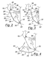
FIG.2 is a top view of the headlamp assembly in a normal operating condition; -
FIG.3 is a top view of the headlamp assembly in a compressed condition; and -
FIG.4 is a top view of the headlamp assembly in a servicing condition. - As seen in
FIG. 1 , a front quarter of anautomotive vehicle 10 includes abumper 12, a hood orbonnet 14, agrill 16, a fender orfront wing 18, and a pedestrianprotection headlamp assembly 20. Agrill opening reinforcement 22 is located behindgrill 16 and provides structural support for the grill and other components. - The
headlamp assembly 20 is located at the outboard corner of the vehicle front quarter and wraps around the corner. As best seen inFIG. 2 ,headlamp assembly 20 preferably includes aheadlamp 24 having atransparent lens 26 enclosing at least one bulb/reflector 28 for projecting a light beam. Many bulbs and/or reflectors may be contained within theheadlamp 26 as called for by styling or functional considerations. -
Headlamp assembly 20 further comprises apivot mechanism 30 disposed adjacent the outboard end ofheadlamp 24 and defining a generally vertical or upwardly extendingpivot axis 32 about which theheadlamp 24 may pivot with respect to the vehicle. - As used herein, the terms "outboard" and "inboard" are with respect to the vehicle as a whole and refer to relative distance from a longitudinal centreline of the vehicle and the term generally vertical means inclined at no more than 45° to the vertical.
- The
pivot mechanism 30 preferably mounts theheadlamp 24 to grilleopening reinforcement 22, but may mount to any vehicle structure adjacent the outboard end of theheadlamp 24. Thepivot mechanism 30 comprises of a rod or pivot pin (not shown) passing through theheadlamp 24 and supported adjacent its upper and lower ends. It will be appreciated that any other appropriate pivot design may be used. - An energy-absorbing
damper 36 is disposed between a rear surface ofheadlamp 24 and extends rearward to the vehicle structure. Thedamper 36 is preferably located adjacent the inboard end ofheadlamp 24 and permits controlled rearward movement of the inboard end of the headlamp as the headlamp rotates aboutpivot mechanism 30. - The
damper 36 may be pneumatic, hydraulic, mechanical, or any other appropriate type of device for absorbing or dissipating kinetic energy. - A
trigger 38 connects the inboard end ofheadlamp 24 togrill 16,hood 14,bumper 12, or other adjacent vehicle structure. Thetrigger 38 holdsheadlamp 24 securely to the adjacent vehicle structure so that theheadlamp 24 is not able to rotate aboutpivot mechanism 30 until a pre-determined threshold level of force is exerted on thetrigger 38. When the threshold level of force is reached, thetrigger 38 releases and permits the inboard end ofheadlamp 24 to move rearward. - The
trigger 38 comprises of a first ring-like fitting 40 secured togrill 16, a second ring-like fitting 42 secured toheadlamp 24 so as to be in alignment with the first fitting when the headlamp is in the normal operating condition (seeFIG. 2 ), and ashear pin 44 passing through the two fittings. It will be appreciated that other constructions could be used to form the trigger and if required the trigger could be collocated with or integrated into thedamper 36. - When a rearward force is applied to the
invention headlamp assembly 20 by striking a pedestrian, thetrigger 38 releasesheadlamp 24 and the inboard end of the headlamp is forced rearward against the resistance provided bydamper 36 as the damper compresses thereby absorbing energy. SeeFIG. 3 . - The controlled movement caused by
damper 36 cushions the impact delivered to the pedestrian byheadlamp 24, thereby reducing the likelihood and/or severity of injury. - The
trigger 38 may be a single-use device as described above that must be replaced after it has releasedheadlamp 24, or may be a re-settable device that functions multiple times without the need for replacement. - The generally vertical or upwardly extending orientation of
pivot axis 32 and its location adjacent the outboard end ofheadlamp 24 yields two main advantages. - First, because the
headlamp 24 is relatively wide it is able to move rearward a substantial distance and so absorb a significant amount of impact energy. For a headlamp used on an average sized passenger vehicle, a rotation of approximately 6° aboutpivot axis 32 corresponds to a rearward movement of approximately 45 mm adjacent the inboard end of theheadlamp 24. Second, theheadlamp assembly 20 is able to absorb an impact that takes place anywhere over the vertical extent of theheadlamp 24. This results in theheadlamp assembly 20 providing injury reduction benefits in the case of a lower leg impact as well as an upper leg impact. - For optimum absorption of impact energy, the
pivot axis 32 should be oriented perpendicular to the direction of impact by a pedestrian on theheadlamp 24. Depending upon the vehicle geometry and the stature of the pedestrian, the expected direction of pedestrian impact may be inclined downwardly from the horizontal. With this in mind, it has been found beneficial to move the upper end of thepivot axis 32 toward the rear of the vehicle so that the axis is tilted to the rear by an angle of from approximately 10° to approximately 30°. -
Trigger 38 may also be released manually anddamper 36 detached fromheadlamp 24 so that theheadlamp 24 can be rotated forward, as shown inFIG. 4 . This forward rotation allows access to the rear surface ofheadlamp 24 so that repairs and/or maintenance can be performed. - The
headlamp 24 may be designed to break, yield, flex, crush, and/or deform under the force of a pedestrian impact in order to absorb additional impact energy. - While a preferred embodiment of the invention has been described in detail, those familiar with the art to which this invention relates will recognize that various alternative designs and embodiments for practicing the invention could be constructed without departing from the scope of the invention, as defined in the claims.
Claims (9)
- A pedestrian protection headlamp assembly (20) for a motor vehicle (10) comprising a headlamp (24) having an inboard end and an outboard end mountable to the vehicle (10) to form a part of a front corner of the vehicle (10), whereby the outboard end of the headlamp (24) is connected by a fixed pivot mechanism (30) to the vehicle, and the inboard end of the headlamp is connected to the vehicle (10) by a damper (36) disposed inboard of the pivot mechanism (30), the damper (36) allowing controlled rearward movement of the inboard end of the headlamp (24) relative to the vehicle when a force applied to the headlamp (24) causes rotation of the headlamp (24) about the pivot mechanism (30) ; characterised in that (10) the pivot mechanism (30) permits the headlamp (24) to rotate relative to the vehicle (10) about a pivot axis (32)that is inclined rearward from the vertical at no more than 45°, such that only the inboard end of the headlamp (24) can move rearwardly relative to the vehicle.
- A headlamp assembly as claimed in claim 1, wherein the pivot axis (32) is inclined rearward from vertical by an angle of between 10 degrees and 30 degrees.
- A headlamp assembly as claimed in claim 1 or 2, wherein the pivot mechanism (30) is adapted to secure the headlamp (24) to a grill opening reinforcement (22).
- A headlamp assembly as claimed in any of claims 1 to 3, wherein the damper (36) is located adjacent an inboard end of the headlamp (24).
- A headlamp assembly as claimed in any of claims 1 to 4, further comprising a trigger (38) preventing rotation of the headlamp (24) about the pivot axis (32) when the force applied to the headlamp (24) is below a threshold value and permitting the headlamp (24) to rotate rearward when the force applied reaches or exceeds the threshold value.
- A headlamp assembly as claimed in claim 5, wherein the trigger (38) is disposed adjacent the inboard end of the headlamp (24) and connects the headlamp (24) to the vehicle (10).
- A headlamp assembly as claimed in claim 5 or in claim 6, wherein the trigger (38) is manually releasable and after the trigger (38) is released the pivot mechanism (30) is operable to allow the headlamp (24) to rotate forward with respect to the vehicle (10) in order to provide access to a rear surface of the headlamp (24).
- A headlamp assembly as claimed in any of claims 1 to 7, wherein the headlamp (24) is adapted to absorb energy by deforming during an impact.
- A motor vehicle (10) characterised in that the motor vehicle (10) has a pedestrian protection headlamp assembly (20) as claimed in any of claims 1 to 8.
Applications Claiming Priority (2)
| Application Number | Priority Date | Filing Date | Title |
|---|---|---|---|
| US09/683,654 US20030142503A1 (en) | 2002-01-30 | 2002-01-30 | Pedestrian protection headlamp |
| US683654 | 2002-01-30 |
Publications (3)
| Publication Number | Publication Date |
|---|---|
| EP1332915A2 EP1332915A2 (en) | 2003-08-06 |
| EP1332915A3 EP1332915A3 (en) | 2007-02-21 |
| EP1332915B1 true EP1332915B1 (en) | 2011-12-28 |
Family
ID=24744930
Family Applications (1)
| Application Number | Title | Priority Date | Filing Date |
|---|---|---|---|
| EP03100015A Expired - Lifetime EP1332915B1 (en) | 2002-01-30 | 2003-01-07 | A pedestrian protection headlamp assembly |
Country Status (2)
| Country | Link |
|---|---|
| US (1) | US20030142503A1 (en) |
| EP (1) | EP1332915B1 (en) |
Cited By (2)
| Publication number | Priority date | Publication date | Assignee | Title |
|---|---|---|---|---|
| EP4197858A1 (en) | 2021-12-16 | 2023-06-21 | ZKW Group GmbH | Shock absorbing vehicle headlight system |
| EP4296120A1 (en) | 2022-06-21 | 2023-12-27 | ZKW Group GmbH | Shock absorbing vehicle headlight system |
Families Citing this family (22)
| Publication number | Priority date | Publication date | Assignee | Title |
|---|---|---|---|---|
| FR2844757B1 (en) * | 2002-09-20 | 2005-10-07 | Valeo Vision | MOTOR VEHICLE PROJECTOR COMPRISING IMPROVED VEHICLE CHASSIS CONNECTION MEANS |
| DE10357920B4 (en) * | 2003-12-11 | 2009-07-09 | Daimler Ag | Vehicle lighting device |
| DE102004013536A1 (en) * | 2004-03-19 | 2005-10-13 | Rehau Ag + Co | Headlight assembly for a motor vehicle |
| DE102004054020A1 (en) * | 2004-11-05 | 2006-05-18 | Peguform Gmbh | headlamp housing |
| DE102005012760A1 (en) * | 2005-03-19 | 2006-09-21 | GM Global Technology Operations, Inc., Detroit | Automotive body |
| FR2895954B1 (en) * | 2006-01-11 | 2008-04-11 | Peugeot Citroen Automobiles Sa | DEVICE FOR MOUNTING AN OPTICAL BLOCK BETWEEN STRUCTURAL ELEMENTS OF A MOTOR VEHICLE AND OPTICAL BLOCK COMPRISING SUCH A DEVICE FOR MOUNTING. |
| FR2903050B1 (en) * | 2006-06-30 | 2009-02-27 | Valeo Systemes Thermiques | LIGHTING OR SIGNALING DEVICE FOR FRONT PANEL OF MOTOR VEHICLE AND FRONT PANEL HAVING SUCH A DEVICE |
| DE102007020915A1 (en) * | 2007-05-04 | 2008-11-06 | GM Global Technology Operations, Inc., Detroit | Front section of motor vehicle has headlamp held in frame, movable between normal position and lowered position and acted on by spring element when in normal position |
| US20090066096A1 (en) * | 2007-09-06 | 2009-03-12 | Doroghazi William J | Vehicle grille including structural inner and decorative outer snap-in features with, and/or method of making the same |
| US9033399B2 (en) * | 2010-03-01 | 2015-05-19 | Sabic Global Technologies B.V. | Energy absorber elements and vehicle systems |
| DE102011011701A1 (en) * | 2011-02-18 | 2012-08-23 | Gm Global Technology Operations, Llc | Mounting bracket for mounting module of front headlight of motor vehicle, comprises receptacle recess for headlight, and pivot support for front headlight, which is engaged with one or multiple support elements |
| FR2983141B1 (en) | 2011-11-24 | 2014-08-08 | Renault Sa | A PROJECTOR ASSEMBLY AND ITS MOUNTING DEVICE LIMITING THE REPAIRS OF THE ADJACENT WING DURING A SHOCK AND THE CORRESPONDING VEHICLE |
| DE102012011596B3 (en) * | 2012-06-13 | 2013-07-04 | Decoma (Germany) Gmbh | cradle |
| DE102013004461B4 (en) * | 2013-03-14 | 2020-10-22 | Audi Ag | Rear bumper and motor vehicle with such a rear bumper |
| US9073478B2 (en) * | 2013-03-29 | 2015-07-07 | GM Global Technology Operations LLC | Energy absorbing headlamp assembly and a resettable headlamp assembly |
| GB2522613A (en) * | 2014-01-06 | 2015-08-05 | Nissan Motor Mfg Uk Ltd | Front end impact structure |
| FR3016577B1 (en) * | 2014-01-22 | 2017-12-22 | Peugeot Citroen Automobiles Sa | FRONT FRONT OF MOTOR VEHICLE WITH RUPTURE FIXING FOR PROJECTOR |
| US10400977B2 (en) * | 2017-02-27 | 2019-09-03 | Motor Coach Industries Limited | Quick adjust vehicle headlight assembly |
| EP3501894B1 (en) * | 2017-12-19 | 2024-07-10 | Ningbo Geely Automobile Research & Development Co., Ltd. | A device for suspension of a lamp in a vehicle |
| EP3501893B1 (en) * | 2017-12-19 | 2023-12-06 | Ningbo Geely Automobile Research & Development Co. Ltd. | A device for suspension of a lamp in a vehicle |
| DE102018211811A1 (en) | 2018-07-16 | 2020-01-16 | Bayerische Motoren Werke Aktiengesellschaft | Front light assembly of a vehicle |
| FR3121402A1 (en) * | 2021-03-30 | 2022-10-07 | Psa Automobiles Sa | System for fixing a headlamp to a vehicle. |
Family Cites Families (9)
| Publication number | Priority date | Publication date | Assignee | Title |
|---|---|---|---|---|
| DE2542920C3 (en) * | 1975-09-26 | 1979-10-25 | Dr.Ing.H.C. F. Porsche Ag, 7000 Stuttgart | Bumpers for vehicles, in particular motor vehicles |
| US4466646A (en) * | 1983-02-25 | 1984-08-21 | General Motors Corporation | Energy absorbing bumper assembly for vehicles |
| DE3802104A1 (en) | 1988-01-26 | 1989-08-03 | Bayerische Motoren Werke Ag | Arrangement of a vehicle lighting unit |
| IT221656Z2 (en) * | 1989-10-13 | 1994-07-25 | Iveco Fiat | BODY ELEMENT OF A VEHICLE INCORPORATING A LIGHTING DEVICE. |
| DE4142582A1 (en) * | 1991-12-21 | 1993-06-24 | Porsche Ag | BUMPER FOR VEHICLES, IN PARTICULAR MOTOR VEHICLES |
| DE19732745A1 (en) * | 1997-07-30 | 1999-02-04 | Bosch Gmbh Robert | Fastening arrangement of a lighting device on a vehicle |
| US6331068B1 (en) * | 1999-02-18 | 2001-12-18 | Lacks Industries, Inc. | Flexible lamp mounting |
| FR2792588B1 (en) * | 1999-04-26 | 2001-07-13 | Peugeot Citroen Automobiles Sa | DEVICE FOR MOUNTING AN OPTICAL BLOCK ON BODY ELEMENTS OF A MOTOR VEHICLE |
| DE19955648C2 (en) * | 1999-11-19 | 2001-10-31 | Audi Ag | Headlamp arrangement |
-
2002
- 2002-01-30 US US09/683,654 patent/US20030142503A1/en not_active Abandoned
-
2003
- 2003-01-07 EP EP03100015A patent/EP1332915B1/en not_active Expired - Lifetime
Cited By (2)
| Publication number | Priority date | Publication date | Assignee | Title |
|---|---|---|---|---|
| EP4197858A1 (en) | 2021-12-16 | 2023-06-21 | ZKW Group GmbH | Shock absorbing vehicle headlight system |
| EP4296120A1 (en) | 2022-06-21 | 2023-12-27 | ZKW Group GmbH | Shock absorbing vehicle headlight system |
Also Published As
| Publication number | Publication date |
|---|---|
| EP1332915A3 (en) | 2007-02-21 |
| EP1332915A2 (en) | 2003-08-06 |
| US20030142503A1 (en) | 2003-07-31 |
Similar Documents
| Publication | Publication Date | Title |
|---|---|---|
| EP1332915B1 (en) | A pedestrian protection headlamp assembly | |
| US7452112B2 (en) | Energy absorbing headlight for a motor vehicle and a method of absorbing the energy produced by pedestrian impact | |
| US7097222B2 (en) | Vehicle anti-crash safety device | |
| US6412581B2 (en) | Radiator mounting structure | |
| US6415883B1 (en) | Deployable A-pillar covers for pedestrian protection | |
| JP3335228B2 (en) | Vehicle headlights | |
| JP2001233121A (en) | Supporting device for lighting fixture for vehicle | |
| EP3501894B1 (en) | A device for suspension of a lamp in a vehicle | |
| US20200298745A1 (en) | Device for suspension of a lamp in a vehicle | |
| CN100377925C (en) | System for preventing window suddenly drop into driver's cab of motor-trolley when collision | |
| JP3762904B2 (en) | Boundary structure between bonnet and headlight | |
| EP2112020B1 (en) | Headlamp assembly and vehicle | |
| KR100691199B1 (en) | Lower stiffener assembly with combined use of stiffener for protecting pedestrian and bumper lip | |
| JP2006001344A (en) | Attaching structure of lighting fixture for vehicle | |
| RU2565439C1 (en) | Headlight device for vehicle | |
| CN212766104U (en) | Buffer mechanism of vehicle engine hood and vehicle | |
| JPS58211975A (en) | Supporting structure of car hood | |
| KR100448161B1 (en) | Hood hinge in an automobile | |
| EP2423056B1 (en) | A safety device | |
| KR100410938B1 (en) | Impact absorbing device of head lamp for vehicle | |
| JP2007537923A (en) | Improved automotive headlamp | |
| KR100696041B1 (en) | Impact absorbing device for head lamp in vehicle | |
| KR100471477B1 (en) | Impact absorption structure of automobile hood panel | |
| KR100542103B1 (en) | Bumper supply structure for vehicles | |
| KR200166593Y1 (en) | Safety bumper |
Legal Events
| Date | Code | Title | Description |
|---|---|---|---|
| PUAI | Public reference made under article 153(3) epc to a published international application that has entered the european phase |
Free format text: ORIGINAL CODE: 0009012 |
|
| AK | Designated contracting states |
Designated state(s): AT BE BG CH CY CZ DE DK EE ES FI FR GB GR HU IE IT LI LU MC NL PT SE SI SK TR |
|
| AX | Request for extension of the european patent |
Extension state: AL LT LV MK RO |
|
| PUAL | Search report despatched |
Free format text: ORIGINAL CODE: 0009013 |
|
| AK | Designated contracting states |
Kind code of ref document: A3 Designated state(s): AT BE BG CH CY CZ DE DK EE ES FI FR GB GR HU IE IT LI LU MC NL PT SE SI SK TR |
|
| AX | Request for extension of the european patent |
Extension state: AL LT LV MK RO |
|
| 17P | Request for examination filed |
Effective date: 20070804 |
|
| AKX | Designation fees paid |
Designated state(s): DE GB SE |
|
| 17Q | First examination report despatched |
Effective date: 20071031 |
|
| GRAP | Despatch of communication of intention to grant a patent |
Free format text: ORIGINAL CODE: EPIDOSNIGR1 |
|
| RAP1 | Party data changed (applicant data changed or rights of an application transferred) |
Owner name: VOLVO CAR CORPORATION |
|
| GRAS | Grant fee paid |
Free format text: ORIGINAL CODE: EPIDOSNIGR3 |
|
| GRAA | (expected) grant |
Free format text: ORIGINAL CODE: 0009210 |
|
| AK | Designated contracting states |
Kind code of ref document: B1 Designated state(s): DE GB SE |
|
| REG | Reference to a national code |
Ref country code: GB Ref legal event code: FG4D |
|
| REG | Reference to a national code |
Ref country code: DE Ref legal event code: R096 Ref document number: 60339529 Country of ref document: DE Effective date: 20120301 |
|
| REG | Reference to a national code |
Ref country code: SE Ref legal event code: TRGR |
|
| PLBE | No opposition filed within time limit |
Free format text: ORIGINAL CODE: 0009261 |
|
| STAA | Information on the status of an ep patent application or granted ep patent |
Free format text: STATUS: NO OPPOSITION FILED WITHIN TIME LIMIT |
|
| 26N | No opposition filed |
Effective date: 20121001 |
|
| REG | Reference to a national code |
Ref country code: DE Ref legal event code: R097 Ref document number: 60339529 Country of ref document: DE Effective date: 20121001 |
|
| PGFP | Annual fee paid to national office [announced via postgrant information from national office to epo] |
Ref country code: SE Payment date: 20150123 Year of fee payment: 13 Ref country code: GB Payment date: 20150120 Year of fee payment: 13 |
|
| GBPC | Gb: european patent ceased through non-payment of renewal fee |
Effective date: 20160107 |
|
| PG25 | Lapsed in a contracting state [announced via postgrant information from national office to epo] |
Ref country code: GB Free format text: LAPSE BECAUSE OF NON-PAYMENT OF DUE FEES Effective date: 20160107 |
|
| PG25 | Lapsed in a contracting state [announced via postgrant information from national office to epo] |
Ref country code: SE Free format text: LAPSE BECAUSE OF NON-PAYMENT OF DUE FEES Effective date: 20160108 |
|
| PGFP | Annual fee paid to national office [announced via postgrant information from national office to epo] |
Ref country code: DE Payment date: 20170116 Year of fee payment: 15 |
|
| REG | Reference to a national code |
Ref country code: DE Ref legal event code: R119 Ref document number: 60339529 Country of ref document: DE |
|
| PG25 | Lapsed in a contracting state [announced via postgrant information from national office to epo] |
Ref country code: DE Free format text: LAPSE BECAUSE OF NON-PAYMENT OF DUE FEES Effective date: 20180801 |