EP1332860A1 - Mold clamping device, mold clamping method, and mold thickness adjusting method using the device - Google Patents
Mold clamping device, mold clamping method, and mold thickness adjusting method using the device Download PDFInfo
- Publication number
- EP1332860A1 EP1332860A1 EP01976809A EP01976809A EP1332860A1 EP 1332860 A1 EP1332860 A1 EP 1332860A1 EP 01976809 A EP01976809 A EP 01976809A EP 01976809 A EP01976809 A EP 01976809A EP 1332860 A1 EP1332860 A1 EP 1332860A1
- Authority
- EP
- European Patent Office
- Prior art keywords
- die
- small
- diameter
- ram
- oil
- Prior art date
- Legal status (The legal status is an assumption and is not a legal conclusion. Google has not performed a legal analysis and makes no representation as to the accuracy of the status listed.)
- Granted
Links
Images


Classifications
-
- B—PERFORMING OPERATIONS; TRANSPORTING
- B29—WORKING OF PLASTICS; WORKING OF SUBSTANCES IN A PLASTIC STATE IN GENERAL
- B29C—SHAPING OR JOINING OF PLASTICS; SHAPING OF MATERIAL IN A PLASTIC STATE, NOT OTHERWISE PROVIDED FOR; AFTER-TREATMENT OF THE SHAPED PRODUCTS, e.g. REPAIRING
- B29C45/00—Injection moulding, i.e. forcing the required volume of moulding material through a nozzle into a closed mould; Apparatus therefor
- B29C45/17—Component parts, details or accessories; Auxiliary operations
- B29C45/64—Mould opening, closing or clamping devices
- B29C45/67—Mould opening, closing or clamping devices hydraulic
- B29C45/6707—Mould opening, closing or clamping devices hydraulic without relative movement between the piston and the cylinder of the clamping device during the mould opening or closing movement
- B29C45/6714—Mould opening, closing or clamping devices hydraulic without relative movement between the piston and the cylinder of the clamping device during the mould opening or closing movement using a separate element transmitting the mould clamping force from the clamping cylinder to the mould
- B29C45/6728—Mould opening, closing or clamping devices hydraulic without relative movement between the piston and the cylinder of the clamping device during the mould opening or closing movement using a separate element transmitting the mould clamping force from the clamping cylinder to the mould the separate element consisting of coupling rods
Definitions
- the present invention relates to a die clamping apparatus , a die clamping method, and a method for adjustment to die thickness using the die clamping apparatus, which are used for an injection molding machine or the like.
- a die clamping apparatus for an injection molding machine which includes a fixed die plate for holding a fixed die, a moving die plate for holding a moving die, displacing means for advancing and retreating the moving die plate with respect to the fixed die plate, and die clamping means for coupling and pressing the moving die plate to the fixed die plate via a tie bar.
- the conventional die clamping apparatus is configured so that the moving die plate is advanced or retreated with respect to the fixed die plate by using a hydraulic cylinder with a small diameter and a long stroke, whereby the die can be moved rapidly when a product is taken out.
- the position of the moving die plate at the time of die closure and opening changes, and accordingly the connecting position of the moving die plate and the tie bar also changes. Therefore, each time the die is replaced, it is necessary to change the position of the moving die plate to adjust the connecting position of the moving die plate and the tie bar.
- FIG. 4 shows a die clamping apparatus for an injection molding machine described in the aforementioned Publication and, more particularly, a typical die clamping apparatus provided with a device for adjusting the position of a moving die plate.
- This die clamping apparatus has means for coupling and pressing a moving die plate 9 to a fixed die plate 5 via a plurality of tie bars 15.
- This coupling/pressing means includes die clamping cylinders 11 incorporated in the fixed die plate 5, the tie bars 15 each of which is connected directly to a ram 13 in the die clamping cylinder 11 and has ring grooves 15a at the distal end portion thereof, and half nuts 29 installed on the moving die plate 9. The half nuts 29 can position the moving die plate 9 by being engaged with the ring grooves 15a in the tie bar 15.
- this die clamping apparatus includes driving means (an auxiliary cylinder 47, a piston 49) for advancing and retreating the ram 13 when each of the die clamping cylinders 11 is not under pressure (under atmospheric pressure), tie bar position detecting means (a position sensor 55, a scale 57) for detecting an individual position in the movement direction of each of the tie bars 15, and moving die plate position detecting means (a position sensor 41, a scale 43) for detecting a position in the movement direction of the moving die plate 9.
- the relative position of the half nuts 29 and the tie bar 15 is calculated individually based on the detection signal sent form these detecting means, and thus the aforementioned driving means (not shown) is controlled so that the half nuts 29 are engaged with the ring grooves 15a in the tie bar 15.
- This control unit uses ordinary means, and therefore the description thereof is omitted.
- the manufacturing cost is high. Also, before the pressure is increased to clamp the die, it is necessary to move the tie bars 15 to the right in FIG. 4 in advance by sending a pressure oil into the die clamping cylinder 11 in order to eliminate a gap between the ring grooves 15a in the die bar 15 and the ring grooves in the half nuts 29.
- the die clamping cylinder 11 of the die clamping apparatus is generally formed so as to have a large diameter because it must provide a high clamping force, so that it is necessary to supply a large quantity of pressure oil to operate the die clamping cylinder 11. Therefore, there arises a problem in that useless time is produced during the time from when the pressure oil is poured to when the tie bar moves.
- an object of the present invention is to provide a die clamping apparatus in which the number of construction parts is small, so that the apparatus can be manufactured at a low cost, and also to provide a die clamping apparatus, a die clamping method, and a method for adjustment to die thickness using the apparatus, in which useless time for eliminating a gap between the ring grooves in the tie bar and the engagement teeth of the half nuts can be reduced a loss of time in the adjustment to die thickness necessary when the die is replaced.
- the present invention provides a die clamping apparatus comprising a fixed die plate for holding a fixed die; a moving die plate for holding a moving die; displacing means for advancing and retreating the moving die plate with respect to the fixed die plate; and die clamping means, which is incorporated in either one of the fixed die plate and the moving die plate, for coupling and pressing the moving die plate to the fixed die plate via a tie bar
- the die clamping means is provided with a die clamping cylinder consisting of two stages of a large-diameter cylinder and a small-diameter cylinder, and a ram formed into two stages of a large-diameter ram and a small-diameter ram; the large-diameter ram is inserted in the large-diameter cylinder, and the small-diameter ram is inserted in the small-diameter cylinder; the proximal end portion of the tie bar is connected directly to the small-diameter
- the present invention provides a die clamping method in which using the above-described die clamping apparatus, a pressure oil is supplied to the small oil chamber to move the tie bar, and after an engagement gap between the half nuts and the tie bar is eliminated, a pressure oil is supplied to the small oil chamber and the large oil chamber on the small ram side to create a die clamping force.
- the present invention provides a method for adjustment to die thickness, in which when adjustment to die thickness is made using the above-described die clamping apparatus, the ram is located at a position of limit end to which the ram can be moved, and after the pressures in the large oil chambers on both sides of the large-diameter ram are decreased, a pressure oil is supplied to the small oil chamber to move the ram in the die clamping direction, by which the tie bar is located at a position at which the ring grooves in the tie bar engage properly with the ring grooves in the half nuts.
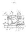
- FIGS. 1 and 2 show an injection molding machine provided with a die clamping apparatus of this embodiment.
- the same reference numerals are applied to elements which are the same as those shown in FIG. 4.
- the injection molding machine of this embodiment has a support frame 1, and a fixed die plate 5 for installing a fixed die 3 is fixedly provided on the support frame 1 (see FIG. 1). Also, a moving die plate 9 for installing a moving die 7 is provided on the support frame 1 so as to face the fixed die plate 5. Further, rails 39 are fixedly provided on the support frame 1 so that linear bearings 35 are guided by the rails 39. The linear bearings 35 support the moving die plate 9 via a base 37. Thereby, the moving die plate 9 can be moved on the support frame 1 along the rails 39.
- the fixed die plate 5 is provided with a plurality of hydraulic die clamping cylinders (four in the example, but needless to say, the number of cylinders is not limited to this number).
- Each of the die clamping cylinders is formed into two stages of a large-diameter cylinder 11 with a short stroke and a small-diameter cylinder 31.
- a ram inserted in the die clamping cylinder is formed into two stages of a large-diameter ram 13 and a small-diameter ram 25.
- the large-diameter ram 13 slidingly moves in the large-diameter cylinder 11, and the small-diameter ram 25 slidingly moves in the small-diameter cylinder 31.
- the proximal end portion of a tie bar 15 is directly connected.
- the moving die plate 9 is formed with insertion holes 27 for the tie bars 15. Therefore, when the moving die plate 9 approaches the fixing die plate 5 for the purpose of die closure, the tie bar 15 can penetrate the insertion hole 27.
- a plurality of ring grooves (or a thread groove) 15a are formed.
- large-diameter oil chambers (hereinafter referred to as large oil chambers) 11c and 11d are formed. Also, on the left-hand side in FIG. 2 of the small-diameter ram 25 in the small-diameter cylinder 31, a small-diameter oil chamber (hereinafter referred to as a small oil chamber) 11e is formed. An opening on the right-hand side of the large-diameter cylinder 11 is closed tightly by a cover 45.
- the tie bar 15 is provided with a position sensor 55, and the fixed die plate 5 is provided with a scale 57 having a detection scale groove or a detection scale magnet.
- die bar position detecting means which detects the positions of the large-diameter ram 13 and the tie bar 15 and the travel distance of the tie bar 15 is formed.
- the moving die plate 9 is provided with a position sensor 41, and a scale 43 having a detection scale groove or a detection scale magnet is fixedly provided on a member installed to the support frame 1.
- a position sensor 41 By the position sensor 41 and the scale 43, moving die plate position detecting means which detects the position and travel distance of the moving die plate 9 is formed.
- a hydraulic moving cylinder 17 At one side of the fixed die plate 5 is fixedly provided a hydraulic moving cylinder 17.
- the proximal end portion of a rod 23 is connected directly to a piston 21 in the moving cylinder 17, and the distal end of the rod 23 is fixed to the side face of the moving die plate 9.
- the moving die plate 9 is provided with half nuts 29 which engage with the ring grooves 15a in the tie bar 15 so that the center thereof coincides with the axis of the insertion hole 27.
- the half nuts 29, which are a so-called split nut divided into plural numbers in the circumferential direction, are configured so as to be opened and closed by a hydraulic cylinder 29a or the like (see FIG. 2) disposed at right angles to the axis of the insertion hole 27 (that is, in the radial direction of the insertion hole 27).
- a support member 33 for supporting the half nuts 29 is provided on the outside face of the moving die plate 9.
- the support member 33 supports the half nuts 29 to prevent the half nuts 29 from separating from the moving die plate 9, for example, when the tie bar engaging with the closed half nuts is pushed in the left direction in FIG. 1 by an oil pressure applied onto the head side of the large-diameter ram 13 for the purpose of die opening etc.
- reference numeral 19 denotes an injection cylinder
- the two-dot chain line indicates the position of the moving die plate 9 in the state of die closure.
- FIG. 2 a detecting section for detecting a relative position of the moving die plate 9 and the tie bar 15 is enlargedly shown. Also, a part of an oil pressure control system for the die clamping cylinder and a control unit 77 for controlling the positions of the rams 13 and 25 through the oil pressure control system.
- This oil pressure control system has oil pressure supply means including oil pressure switching valves 61, 63 and 65, a low hydraulic power source (not shown), and a high hydraulic power source (not shown).
- the oil pressure switching valve 61 is a four-way switching electromagnetic valve having a block port for supplying a pressure oil to the small-diameter cylinder 31.
- One port of the oil pressure switching valve 61 is connected with a high-pressure oil pipe 67, and the other port thereof is connected with an oil pipe 71.
- the oil pipe 71 is connected to a port 31a in the fixed die plate 5 communicating with the small oil chamber 11e in the small-diameter cylinder 31.
- the oil pressure switching valve 63 is a three-way switching electromagnetic valve having a block port for supplying a high-pressure oil (for example, 175 kgf/cm 2 ) from the high-pressure oil pipe 67 or a low-pressure oil (for example, 40 kgf/cm 2 ) from a low-pressure oil pipe 69 to the large-diameter cylinder 11 by switching.
- the oil pressure switching valve 65 is a three-way switching electromagnetic valve which applies a die clamping force and a die opening force to the large-diameter ram 13 by switching the oil pressures in the large oil chambers 11c and 11d on both sides of the large-diameter ram 13 in the large-diameter cylinder 11.
- An oil pipe 73 is connected to a port 11a communicating with the large oil chamber 11d on the die clamping side (left-hand side in FIG. 2) of the large-diameter cylinder 11.
- An oil pipe 75 is connected to a port 11b communicating with the large oil chamber 11c on the die opening side (right-hand side in FIG. 2) of the large-diameter cylinder 11.
- the oil pressure switching valve 65 operates in the direction such as to cause a pressure oil to flow, so that the same oil pressure acts on both side faces of the large-diameter ram 13 in the large-diameter cylinder 11.
- the oil pressure acting area (area subjected to pressure) on the left-hand side of the large-diameter ram 13 is smaller than that on the right-hand side thereof by the area of the small-diameter ram 25, so that an oil pressure acting force in the die opening direction (the left direction in FIG. 2) of the large-diameter ram 13 is increased by a difference in oil pressure acting area between both side faces of the large-diameter ram 13, whereby a die opening force is created on the large-diameter ram 13.
- a die that serves as a reference (hereinafter referred to as a reference die) is installed to each of the fixed die plate 5 and the moving die plate 9.
- the moving die plate 9 is moved by the moving cylinder 17, by which the die 7 is closed.
- the position at which the die is closed is taken as a reference position S 0 of the moving die plate 9, and the position of the scale 43 detected by the position sensor 41 of the moving die plate 9 is taken as an initial point 0 for calculation.
- the reference position S 0 and the initial point 0 are stored in the control unit 77.
- the position of the large-diameter ram 13 is calculated from the distance from the attachment face of the die 7 of the moving die plate 9 to the position of ring groove in the half nuts 29 and the distance from the right end portion of the large-diameter ram 13 in FIG. 2 to the position of the ring groove 15a in the tie bar 15 so that the tie bar 15 and the half nuts 29 are engaged properly with each other, and the calculated position is taken as a reference position T 0 of the large-diameter ram 13.
- the position T 0 is stored in the control unit 77 as the initial point 0 for the calculation of the tie bar position detecting position sensor 55.
- the oil pressure switching valve 63 is operated to a position at which a pressure oil does not flow (hereinafter referred to as a block position), and the oil pressure switching valve 65 is operated in the direction in which a pressure oil flows by making the electromagnetic coil Z non-excited.
- the difference in oil pressure between the large oil chambers 11c and 11d on both sides of the large-diameter ram 13 in the large-diameter cylinder 11 is made zero.
- an electromagnetic coil X 2 of the oil pressure switching valve 61 is excited, by which a high-pressure oil is sent to the port 31a.
- the small-diameter ram 25 in the small-diameter cylinder 31 is pushed by the high-pressure oil, so that the small-diameter ram 25 is retreated (moved in the right direction in FIG. 2) together with the large-diameter ram 13.
- an electromagnetic coil X 1 is excited to make the oil pressure switching valve 61 in the block position, and the large-diameter ram 13 is stopped at the reference position T 1 . In this state, the moving die plate 9 is moved to close the die.
- the large-diameter ram 13 is located at a position at which the half nuts 29 just engage with the ring grooves 15a in the tie bar 15. Therefore, by moving the half nuts 29 toward the axis thereof by the hydraulic cylinder 29a, the half nuts 29 can be engaged with the ring grooves 15a in the tie bar 15 (see FIG. 2).
- the engagement gap between the tie bar 15 and the half nuts 29 is eliminated, by which the aforementioned gap can be eliminated by using a smaller quantity of hydraulic oil without the use of a large-diameter die clamping cylinder.
- the tie bar 15 can be coupled to the half nuts 29 without a gap in a short period of time, so that a mechanical shock occurring at the time of die clamping can be restrained.
- the electromagnetic coil Z of the oil pressure switching valve 65 is excited to operate the oil pressure switching valve 65 in the direction such as to stop a pressure oil.
- an electromagnetic coil Y 2 of the oil pressure switching valve 63 is excited to operate the oil pressure switching valve 63 so as to cause a high-pressure oil to flow, by which the high-pressure oil is sent to the large oil chamber 11d on the tie bar side of the large-diameter ram 13 in the large-diameter cylinder 11.
- the electromagnetic coil X 2 of the oil pressure switching valve 61 is excited to operate the oil pressure switching valve 61 so as to cause the high-pressure oil to flow, by which the high-pressure oil is sent to the small-diameter cylinder 31.
- the tie bar 15 is pulled toward the fixed die plate 5 with a high force, so that the die clamping operation is performed.
- the electromagnetic coil X 1 of the oil pressure switching valve 61 is excited to make the internal pressure of the small-diameter cylinder 31 zero (atmospheric pressure), and an electromagnetic coil Y 1 of the oil pressure switching valve 63 is excited to operate the oil pressure switching valve 63 so as to communicate with the low-pressure oil pipe 69.
- the electromagnetic coil Z of the oil pressure switching valve 65 is made non-exited to operate the oil pressure switching valve 65 so as to cause the pressure oil to flow. Thereby, the pressures on both sides of the large-diameter cylinder 11 is made equal.
- the large-diameter ram 13 is moved in the die opening direction (the left direction in FIG. 2).
- the die can be opened slightly in a state in which the tie bar 15 is fixed by the half nuts 29.
- the half nuts 29 are opened to release the connection between the half nuts 29 and the tie bar 15, and the moving die plate 9 is moved in the direction such as to separate from the fixed die plate 5 by the moving cylinder 17, by which the product is taken out by using a take-out robot or the like (not shown).
- the oil pressure switching valve 63 is made in the block position (position at which the pressure oil does not flow).
- the oil switching valve 65 is operated so as to cause the pressure oil to flow to open a passage between the large oil chamber 11c and the large oil chamber lid on both sides of the large-diameter ram 13, by which the difference in pressure between the large oil chamber 11c and the large oil chamber 11d is made zero.
- the electromagnetic coil X 2 of the oil pressure switching valve 61 is excited to switch over the oil pressure switching valve 61 to the direction such as to send the high-pressure oil to the port 31a.
- the small-diameter ram 25 is pushed in the right direction in FIG.
- the position S 0 indicated by the two-dot chain line is a position of the moving die plate 9 for fastening the half nuts 29 when the reference dies are installed to the die plates 5 and 9.
- the moving die plate 9 is in the state in which the movement for die closure is finished and the die clamping operation is not yet started.
- the large-diameter ram 13 is located at the position T 1 , which position is indicated by the two-dot chain line designating the face on the side opposite to the small-diameter ram 25 (on the right side in FIG. 2).
- a replacement die With a thickness different from that of the reference die (hereinafter referred to as a replacement die) will be explained.
- a dimensional difference m in thickness between the reference die and the replacement die is first determined.
- This dimensional difference m is determined from the actually measured value of replacement die. Alternatively, it is determined as follows: a difference in position when the reference die and the replacement die are installed to the moving die plate 9 that is in the die closure state is detected on the scale 43 by the position sensor 41, and the detection result is calculated by the control unit 77.
- the dimensional difference m is divided by a pitch c of the ring grooves 15a, and a residual smaller than indivisible c is taken out. This residual is used as a correction value, and is stored in the control unit 77 as the position of the large-diameter ram 13.
- T 0 indicates a position of limit end to which the large-diameter ram 13 can be moved to the left side in the large-diameter cylinder 11.
- the left-side gape of te large-diameter ram 13 in the large-diameter cylinder 11 can be determined by the aforementioned formula.
- This calculation for determining e is performed by the control unit 77.
- the value e thus determined is stored in the control unit 77, and before the next die clamping operation is started, the tie bar 15 is moved in the right direction in FIG. 2 through a distance of e.
- the value detected by the scale 57 is compared with this value e. When these values become equal to each other, the large-diameter ram 13 is stopped.
- the large-diameter ram 13 has only to be returned slowly to the position T 2 (or T 1 ) during the time from when the die opening by using the large-diameter cylinder 11 is finished to when the next die clamping operation is started, so that the supply of pressure oil to the small oil chamber 11e in the small-diameter cylinder 31 can be effected by using a low-capacity hydraulic power source.
- the large-diameter ram 13 has only to be returned to an arbitrary corrected position T (not shown) before the die clamping operation.
- the opening position of the moving die plate 9 (a clearance between the moving die plate 9 and the fixed die plate 5) can be set by combining the position sensor 41 for detecting the position in the travel direction of the moving die plate 9, the scale 43, and the control unit 77.
- the fixed die plate 5 is provided with the two-stage die clamping cylinder consisting of the large-diameter cylinder 11 and the small-diameter cylinder 31 so that the two-stage ram consisting of the large-diameter ram 13 and the small-diameter ram 25 is slidingly moved in the die clamping cylinder, and the proximal end portion of the tie bar 15 is connected directly to the face on the moving die plate side of the small-diameter ram 25.
- the moving die plate 9 is provided with the insertion hole 27 for the tie bar 15, and the support member 33 for supporting the half nuts 29 is provided. This positional relationship may be changed as described below.
- the moving die plate 9 is provided with a two-stage die clamping cylinder consisting of a large-diameter cylinder and a small-diameter cylinder so that a two-stage ram consisting of a large-diameter ram and a small-diameter ram is slidingly moved in the die clamping cylinder, and the proximal end portion of the tie bar is connected directly to the face on the fixed die plate side of the small-diameter ram.
- the fixed die plate 5 is provided with an insertion hole for the tie bar, and a support member for supporting half nuts is provided.
- the number of construction parts is small as compared with the construction of the conventional die clamping apparatus, so that the die clamping apparatus in accordance with the present invention can be manufactured at a low cost.
- a large operation space can be provided on the side opposite to the die attachment face of the fixed die plate, so that the operability of the apparatus can be increased.
- the relative stop position of the moving die plate with respect to the tie bar can be selected freely, so that the apparatus can accommodate dies with various die thicknesses.
- the tie bar can be engaged with the ring grooves (or thread groove) in the half nuts at any position, the apparatus achieves an effect that it can be used easily for injection compressing or cloth-laid molding.
- the oil pressure switching valve is switched over again in the state in which the large-diameter cylinder is under no pressure to send a high-pressure oil to the small-diameter cylinder, and the tie bar is pulled by using the small-diameter ram in the small-diameter cylinder, by which the gap in the aforementioned engagement is eliminated. Therefore, the operation for eliminating the gap can be performed with a small quantity of pressure oil as compared with the case where the gap is eliminated by pulling the tie bar using a large-diameter die clamping cylinder.
- the tie bar can be connected to the half nuts without a gap in a short period of time. Moreover, since a gap between the half nuts and the moving die plate and other gaps can be eliminated in a short period of time, useless time for eliminating a gap between the ring grooves in the tie bar and the engagement teeth of the half nuts caused by the adjustment to die thickness can be reduced, and further a mechanical shock occurring at the time of die clamping can be restrained.
Landscapes
- Engineering & Computer Science (AREA)
- Manufacturing & Machinery (AREA)
- Mechanical Engineering (AREA)
- Moulds For Moulding Plastics Or The Like (AREA)
- Injection Moulding Of Plastics Or The Like (AREA)
Abstract
Description
Claims (5)
- A die clamping apparatus comprising a fixed die plate for holding a fixed die; a moving die plate for holding a moving die; displacing means for advancing and retreating said moving die plate with respect to said fixed die plate; and die clamping means, which is incorporated in either one of said fixed die plate and said moving die plate, for coupling and pressing said moving die plate to said fixed die plate via a tie bar, wherein
said die clamping means is provided with a die clamping cylinder comprising of two stages of a large-diameter cylinder and a small-diameter cylinder, and a ram formed into two stages of a large-diameter ram and a small-diameter ram; said large-diameter ram is inserted in said large-diameter cylinder, and said small-diameter ram is inserted in said small-diameter cylinder; the proximal end portion of said tie bar is connected directly to said small-diameter ram; a large oil chamber is provided on each side of said large-diameter ram, and a small oil chamber is provided on the tie bar connection side of said small-diameter ram; and oil pressure supply means is provided which appropriately supplies an oil pressure to said large oil chamber and said small oil chamber in said die clamping cylinder to appropriately move said tie bar. - The die clamping apparatus according to claim 1, wherein a plurality of ring grooves with an equal pitch are formed in the distal end portion of said tie bar; half nuts, which engage with the ring grooves in said tie bar, for regulating the movement of said moving die plate are disposed on said fixed die plate or said moving die plate which faces the die plate incorporating said die clamping means; and further there are provided tie bar position detecting means for detecting the position of said tie bar, moving die plate position detecting means for detecting the position of said moving die plate, and a control unit for supplying a pressure oil to said small oil chamber by using said oil pressure supply means based on a detection signal sent from said tie bar position detecting means and said moving die plate position detecting means and controlling the position of said ram so that said half nuts and said tie bar engage with each other.
- The die clamping apparatus according to claim 1 or 2, wherein said oil pressure supply means comprises a first oil pressure switching valve for supplying a high-pressure oil to said small oil chamber or stopping the supply, a second oil pressure switching valve for selectively supplying either a high-pressure oil or a low-pressure oil to said large oil chambers on both sides of said large-diameter ram or stopping the supply, and a third oil pressure switching valve for supplying the pressure oil sent from said second oil pressure switching valve to the large oil chamber located on the small-diameter ram side of said large-diameter ram or stopping the supply.
- A die clamping method in which using the die clamping apparatus as described in claim 1, a pressure oil is supplied to said small oil chamber to move said tie bar, and after an engagement gap between said half nuts and said tie bar is eliminated, a pressure oil is supplied to said small oil chamber and said large oil chamber on the small ram side to create a die clamping force.
- A method for adjustment to die thickness, in which when adjustment to die thickness is made using the die clamping apparatus as described in claim 1, said ram is located at a position of limit end to which said ram can be moved, and after the pressures in said large oil chambers on both sides of said large-diameter ram are decreased, a pressure oil is supplied to said small oil chamber to move said ram in the die clamping direction, by which said tie bar is located at a position at which the ring grooves in said tie bar engage properly with the ring grooves in said half nuts.
Applications Claiming Priority (3)
| Application Number | Priority Date | Filing Date | Title |
|---|---|---|---|
| JP2000322175A JP4055841B2 (en) | 2000-10-23 | 2000-10-23 | Mold clamping apparatus, mold clamping method, and mold thickness adjusting method using the same |
| JP2000322175 | 2000-10-23 | ||
| PCT/JP2001/009270 WO2002034498A1 (en) | 2000-10-23 | 2001-10-23 | Mold clamping device, mold clamping method, and mold thickness adjusting method using the device |
Publications (3)
| Publication Number | Publication Date |
|---|---|
| EP1332860A1 true EP1332860A1 (en) | 2003-08-06 |
| EP1332860A4 EP1332860A4 (en) | 2004-04-07 |
| EP1332860B1 EP1332860B1 (en) | 2010-12-01 |
Family
ID=18800095
Family Applications (1)
| Application Number | Title | Priority Date | Filing Date |
|---|---|---|---|
| EP01976809A Expired - Lifetime EP1332860B1 (en) | 2000-10-23 | 2001-10-23 | Mold clamping device |
Country Status (8)
| Country | Link |
|---|---|
| US (1) | US6821104B2 (en) |
| EP (1) | EP1332860B1 (en) |
| JP (1) | JP4055841B2 (en) |
| CN (1) | CN1189305C (en) |
| CA (1) | CA2395087C (en) |
| DE (1) | DE60143586D1 (en) |
| TW (1) | TW506893B (en) |
| WO (1) | WO2002034498A1 (en) |
Cited By (1)
| Publication number | Priority date | Publication date | Assignee | Title |
|---|---|---|---|---|
| DE102005051787B4 (en) * | 2004-10-29 | 2016-06-30 | Toshiba Kikai K.K. | Form drive unit of a molding machine |
Families Citing this family (37)
| Publication number | Priority date | Publication date | Assignee | Title |
|---|---|---|---|---|
| US20100310552A1 (en) * | 2001-09-18 | 2010-12-09 | Rapp Jeffrey C | Antibodies produced in the avian oviduct |
| JP4472939B2 (en) * | 2003-04-17 | 2010-06-02 | 東芝機械株式会社 | Molding device for injection molding machine |
| US20040247740A1 (en) * | 2003-05-01 | 2004-12-09 | Toshiba Kikai Kabushiki Kaisha | Mold clamping apparatus |
| JP4312498B2 (en) * | 2003-05-06 | 2009-08-12 | 東芝機械株式会社 | Clamping device |
| JP2005053022A (en) * | 2003-08-01 | 2005-03-03 | Meiki Co Ltd | Mold clamping device and mold clamping method |
| JP4546267B2 (en) | 2004-01-30 | 2010-09-15 | 東芝機械株式会社 | Mold clamping device and mold clamping method |
| JP4531436B2 (en) * | 2004-04-13 | 2010-08-25 | 東芝機械株式会社 | Clamping device |
| JP4489509B2 (en) * | 2004-06-17 | 2010-06-23 | 東芝機械株式会社 | Clamping device |
| KR100644344B1 (en) | 2005-04-02 | 2006-11-10 | 엘에스전선 주식회사 | Piston Head of Injection Molding Machine |
| JP4885475B2 (en) * | 2005-05-13 | 2012-02-29 | 東芝機械株式会社 | Mold clamping device such as die casting machine, mold exchanging method having the same mold clamping device, and moving side die plate exchanging system |
| JP4828179B2 (en) * | 2005-08-25 | 2011-11-30 | 東芝機械株式会社 | Clamping device |
| JP4832859B2 (en) * | 2005-11-17 | 2011-12-07 | 東芝機械株式会社 | Mold clamping device and abnormality detection method |
| JP4252592B2 (en) * | 2006-09-04 | 2009-04-08 | 株式会社名機製作所 | Clamping device |
| CN101332665B (en) * | 2007-06-26 | 2010-12-22 | 震雄资产管理有限公司 | Injection molding machine and mold adjusting method |
| KR100873335B1 (en) | 2007-07-11 | 2008-12-10 | 주식회사 우진세렉스 | Clamping Device of Injection Molding Machine |
| US20110059200A1 (en) * | 2009-09-10 | 2011-03-10 | Jung-Teng Lin | Double Mold Locking Apparatus |
| US8580168B1 (en) | 2010-03-16 | 2013-11-12 | Honda Motor Co., Ltd. | System and method to account for thermal die expansion |
| DE102010046227B4 (en) | 2010-05-25 | 2021-08-05 | Kraussmaffei Technologies Gmbh | Method for operating a clamping unit for an injection molding machine |
| JP5631669B2 (en) * | 2010-09-03 | 2014-11-26 | 小島プレス工業株式会社 | Multiple press molding equipment |
| CN102582045A (en) | 2011-01-17 | 2012-07-18 | 三菱重工塑胶科技有限公司 | Die clamping device for injection molding machine |
| SI2691220T1 (en) * | 2011-03-29 | 2016-09-30 | Richter Bodo | Arrangement for receiving a casting mould with coaxial drive and method therefor |
| CN102179486A (en) * | 2011-04-23 | 2011-09-14 | 西南大学 | Die for casting aluminum-clad magnesium alloy composite material |
| AT513666B1 (en) * | 2012-11-26 | 2018-12-15 | Engel Austria Gmbh | Operating unit for an injection molding machine |
| CN203267139U (en) * | 2012-12-03 | 2013-11-06 | 海天塑机集团有限公司 | Mould for testing injection molding machine and injection molding machine testing device |
| CN104669171B (en) * | 2013-11-26 | 2017-12-19 | 海洋王(东莞)照明科技有限公司 | The fit-up gap control fixture of light fixture |
| JP6606457B2 (en) * | 2016-03-31 | 2019-11-13 | U−Mhiプラテック株式会社 | Hydraulic actuator and mold clamping device |
| KR102469661B1 (en) * | 2016-08-19 | 2022-11-22 | 엘에스엠트론 주식회사 | Apparatus for Supporting Tie-bar of Injection Molding Machine |
| CN108227637A (en) * | 2018-02-09 | 2018-06-29 | 东莞辰达电器有限公司 | A control system and control method for a punch press and its auxiliary equipment |
| JP7039362B2 (en) * | 2018-03-30 | 2022-03-22 | 住友重機械工業株式会社 | Injection molding machine |
| KR101901652B1 (en) | 2018-06-28 | 2018-11-05 | 홍석천 | Mold apparatus for molding automobile parts having a two-end pressing structure |
| CN109124309B (en) * | 2018-11-08 | 2020-09-15 | 广东华强电器集团有限公司 | A special machine for pressing the movable cover plate of an electric rice cooker |
| CN110252880B (en) * | 2019-07-29 | 2024-11-05 | 无锡城投建设有限公司 | A taper pin continuous punching device for building templates |
| CN110405037A (en) * | 2019-08-09 | 2019-11-05 | 湖南城市学院 | A hydraulic device for aluminum alloy plate forming |
| CN112477034A (en) * | 2019-09-12 | 2021-03-12 | 日精树脂工业株式会社 | Mold clamping device with split nut and injection molding device |
| CN111331265B (en) * | 2020-04-15 | 2024-11-12 | 昆山允可精密工业技术有限公司 | A multi-diameter adaptive positioning bushing |
| CN112297360A (en) * | 2020-10-26 | 2021-02-02 | 王书旭 | Injection mold that breaks away from fast |
| IT202100006101A1 (en) * | 2021-03-15 | 2022-09-15 | Italpressegauss S P A | DIE CASTING MACHINE |
Family Cites Families (15)
| Publication number | Priority date | Publication date | Assignee | Title |
|---|---|---|---|---|
| DE51182C (en) | Firma HANIEL & LUEG in Düsseldorf-Grafenberg | Innovation in hydraulic differential prefabrication. (2 | ||
| US4021181A (en) * | 1974-04-23 | 1977-05-03 | Karl Hehl | Tie rod connection for die closing unit of injection molding machine |
| US3940930A (en) | 1975-01-20 | 1976-03-02 | Package Machinery Company | Hydraulic system for injection molding machine |
| DE2747548C2 (en) | 1977-10-22 | 1986-04-17 | Thyssen Industrie Ag, 4300 Essen | Press with control circuit |
| JPH01192519A (en) * | 1988-01-29 | 1989-08-02 | Japan Steel Works Ltd:The | Mold clamping device of injection molding machine |
| US5192557A (en) * | 1990-07-27 | 1993-03-09 | Nissei Jushi Kogyo K.K. | Clamping apparatus for molding machine |
| JP2875060B2 (en) | 1991-06-12 | 1999-03-24 | 住友重機械プラスチックマシナリー株式会社 | Mold clamping device for electric injection molding machine |
| JP2704572B2 (en) | 1991-12-26 | 1998-01-26 | 日精樹脂工業株式会社 | Mold clamping device of molding machine |
| JPH07110509B2 (en) | 1992-02-05 | 1995-11-29 | 日精樹脂工業株式会社 | Clamping device for injection molding machine |
| JP2653754B2 (en) * | 1993-11-08 | 1997-09-17 | 日精樹脂工業株式会社 | Mold opening / closing control method for molding machine |
| DE4344340C2 (en) * | 1993-12-23 | 1995-11-16 | Krauss Maffei Ag | Mold closing device for an injection molding machine |
| JPH07119038B2 (en) | 1993-12-27 | 1995-12-20 | 菱屋精工株式会社 | Injection molding machine |
| JP3595367B2 (en) | 1995-04-04 | 2004-12-02 | 三菱重工業株式会社 | Mold thickness adjustment device |
| JP3644257B2 (en) | 1998-06-24 | 2005-04-27 | 宇部興産株式会社 | Molding device clamping machine |
| JP3401446B2 (en) | 1998-12-28 | 2003-04-28 | 東芝機械株式会社 | Mold clamping devices such as injection molding machines |
-
2000
- 2000-10-23 JP JP2000322175A patent/JP4055841B2/en not_active Expired - Lifetime
-
2001
- 2001-10-23 EP EP01976809A patent/EP1332860B1/en not_active Expired - Lifetime
- 2001-10-23 CN CN01803251.6A patent/CN1189305C/en not_active Expired - Fee Related
- 2001-10-23 WO PCT/JP2001/009270 patent/WO2002034498A1/en not_active Ceased
- 2001-10-23 CA CA002395087A patent/CA2395087C/en not_active Expired - Fee Related
- 2001-10-23 US US10/148,905 patent/US6821104B2/en not_active Expired - Fee Related
- 2001-10-23 TW TW090126316A patent/TW506893B/en not_active IP Right Cessation
- 2001-10-23 DE DE60143586T patent/DE60143586D1/en not_active Expired - Lifetime
Cited By (1)
| Publication number | Priority date | Publication date | Assignee | Title |
|---|---|---|---|---|
| DE102005051787B4 (en) * | 2004-10-29 | 2016-06-30 | Toshiba Kikai K.K. | Form drive unit of a molding machine |
Also Published As
| Publication number | Publication date |
|---|---|
| CN1394163A (en) | 2003-01-29 |
| WO2002034498A1 (en) | 2002-05-02 |
| US20020180132A1 (en) | 2002-12-05 |
| EP1332860A4 (en) | 2004-04-07 |
| TW506893B (en) | 2002-10-21 |
| JP2002127216A (en) | 2002-05-08 |
| JP4055841B2 (en) | 2008-03-05 |
| CA2395087A1 (en) | 2002-05-02 |
| DE60143586D1 (en) | 2011-01-13 |
| EP1332860B1 (en) | 2010-12-01 |
| CA2395087C (en) | 2006-05-02 |
| US6821104B2 (en) | 2004-11-23 |
| CN1189305C (en) | 2005-02-16 |
Similar Documents
| Publication | Publication Date | Title |
|---|---|---|
| US6821104B2 (en) | Die clamping apparatus and method, and method for adjustment to die thickness using said apparatus | |
| JP4531436B2 (en) | Clamping device | |
| US7040377B2 (en) | Injection system and casting method of die casting machine | |
| US6581379B2 (en) | Pressure intensifying apparatus for hydraulic cylinder | |
| US20050217475A1 (en) | Air servo cylinder apparatus and controlling method therefor | |
| JP3595367B2 (en) | Mold thickness adjustment device | |
| KR20070024391A (en) | Clamping System and Clamping Method | |
| KR19990023216A (en) | METHOD AND CONTROL APPARATUS FOR CONTROLLING MOLD CONNECTION PRESSURE IN PRESSURE TYPE MOLDING FASTING APPARATUS | |
| JP2004506546A (en) | Plate type clamping unit for injection molding machines | |
| JP2002225103A (en) | Apparatus and method for hydraulically clamping mold of injection molding machine as well as apparatus and method for regulating mold thickness using the same apparatus and method | |
| JPH0755504B2 (en) | Mold clamping method and device | |
| JPH10296811A (en) | Mold clamping method of compound direct pressure mold clamping device | |
| JP2714525B2 (en) | Flow control method of mold clamping cylinder in toggle type injection molding machine | |
| JPH11179770A (en) | Apparatus and method for controlling mold clamping of a compression molding machine | |
| JPH11320637A (en) | Injection compression molding machine | |
| JP2005335075A (en) | Control method of mold clamping device | |
| JPH11129303A (en) | Tie bar locking method and device for compound direct pressure type mold clamping device | |
| JP3237576B2 (en) | Apparatus and method for controlling moving distance of mold opening of movable plate and injection compression molding method | |
| JPH08267522A (en) | Mold clamping device of injection molder | |
| JP2659322B2 (en) | Toggle type mold clamping device | |
| JP6606457B2 (en) | Hydraulic actuator and mold clamping device | |
| JP3089383B2 (en) | Mold clamping device of injection molding machine | |
| JPH07186226A (en) | Injection compression molding device | |
| JPH0773787B2 (en) | Molding machine clamping device | |
| JPH03277523A (en) | Mold clamping device in injection molding apparatus |
Legal Events
| Date | Code | Title | Description |
|---|---|---|---|
| PUAI | Public reference made under article 153(3) epc to a published international application that has entered the european phase |
Free format text: ORIGINAL CODE: 0009012 |
|
| 17P | Request for examination filed |
Effective date: 20020613 |
|
| AK | Designated contracting states |
Designated state(s): DE IT |
|
| A4 | Supplementary search report drawn up and despatched |
Effective date: 20040224 |
|
| 17Q | First examination report despatched |
Effective date: 20040304 |
|
| 17Q | First examination report despatched |
Effective date: 20040304 |
|
| GRAP | Despatch of communication of intention to grant a patent |
Free format text: ORIGINAL CODE: EPIDOSNIGR1 |
|
| RTI1 | Title (correction) |
Free format text: MOLD CLAMPING DEVICE |
|
| GRAS | Grant fee paid |
Free format text: ORIGINAL CODE: EPIDOSNIGR3 |
|
| GRAA | (expected) grant |
Free format text: ORIGINAL CODE: 0009210 |
|
| AK | Designated contracting states |
Kind code of ref document: B1 Designated state(s): DE IT |
|
| REF | Corresponds to: |
Ref document number: 60143586 Country of ref document: DE Date of ref document: 20110113 Kind code of ref document: P |
|
| PLBE | No opposition filed within time limit |
Free format text: ORIGINAL CODE: 0009261 |
|
| STAA | Information on the status of an ep patent application or granted ep patent |
Free format text: STATUS: NO OPPOSITION FILED WITHIN TIME LIMIT |
|
| 26N | No opposition filed |
Effective date: 20110902 |
|
| REG | Reference to a national code |
Ref country code: DE Ref legal event code: R097 Ref document number: 60143586 Country of ref document: DE Effective date: 20110902 |
|
| PGFP | Annual fee paid to national office [announced via postgrant information from national office to epo] |
Ref country code: IT Payment date: 20141017 Year of fee payment: 14 |
|
| PG25 | Lapsed in a contracting state [announced via postgrant information from national office to epo] |
Ref country code: IT Free format text: LAPSE BECAUSE OF NON-PAYMENT OF DUE FEES Effective date: 20151023 |
|
| REG | Reference to a national code |
Ref country code: DE Ref legal event code: R082 Ref document number: 60143586 Country of ref document: DE Representative=s name: HOFFMANN - EITLE PATENT- UND RECHTSANWAELTE PA, DE Ref country code: DE Ref legal event code: R081 Ref document number: 60143586 Country of ref document: DE Owner name: U-MHI PLATECH CO., LTD., NAGOYA-SHI, JP Free format text: FORMER OWNER: MITSUBISHI HEAVY INDUSTRIES, LTD., TOKYO, JP |
|
| PGFP | Annual fee paid to national office [announced via postgrant information from national office to epo] |
Ref country code: DE Payment date: 20191008 Year of fee payment: 19 |
|
| REG | Reference to a national code |
Ref country code: DE Ref legal event code: R119 Ref document number: 60143586 Country of ref document: DE |
|
| PG25 | Lapsed in a contracting state [announced via postgrant information from national office to epo] |
Ref country code: DE Free format text: LAPSE BECAUSE OF NON-PAYMENT OF DUE FEES Effective date: 20210501 |