EP1332820A1 - Cutting tip for rotating cutting tool and rotating cutting tool using the tip, and method of machining using the tool - Google Patents
Cutting tip for rotating cutting tool and rotating cutting tool using the tip, and method of machining using the tool Download PDFInfo
- Publication number
- EP1332820A1 EP1332820A1 EP01974893A EP01974893A EP1332820A1 EP 1332820 A1 EP1332820 A1 EP 1332820A1 EP 01974893 A EP01974893 A EP 01974893A EP 01974893 A EP01974893 A EP 01974893A EP 1332820 A1 EP1332820 A1 EP 1332820A1
- Authority
- EP
- European Patent Office
- Prior art keywords
- cutting
- cutting edge
- single crystal
- crystal diamond
- insert
- Prior art date
- Legal status (The legal status is an assumption and is not a legal conclusion. Google has not performed a legal analysis and makes no representation as to the accuracy of the status listed.)
- Withdrawn
Links
Images



Classifications
-
- B—PERFORMING OPERATIONS; TRANSPORTING
- B23—MACHINE TOOLS; METAL-WORKING NOT OTHERWISE PROVIDED FOR
- B23C—MILLING
- B23C5/00—Milling-cutters
-
- B—PERFORMING OPERATIONS; TRANSPORTING
- B23—MACHINE TOOLS; METAL-WORKING NOT OTHERWISE PROVIDED FOR
- B23C—MILLING
- B23C5/00—Milling-cutters
- B23C5/16—Milling-cutters characterised by physical features other than shape
- B23C5/20—Milling-cutters characterised by physical features other than shape with removable cutter bits or teeth or cutting inserts
- B23C5/202—Plate-like cutting inserts with special form
-
- B—PERFORMING OPERATIONS; TRANSPORTING
- B23—MACHINE TOOLS; METAL-WORKING NOT OTHERWISE PROVIDED FOR
- B23C—MILLING
- B23C5/00—Milling-cutters
- B23C5/16—Milling-cutters characterised by physical features other than shape
- B23C5/20—Milling-cutters characterised by physical features other than shape with removable cutter bits or teeth or cutting inserts
- B23C5/22—Securing arrangements for bits or teeth or cutting inserts
- B23C5/2204—Securing arrangements for bits or teeth or cutting inserts with cutting inserts clamped against the walls of the recess in the cutter body by a clamping member acting upon the wall of a hole in the insert
- B23C5/2226—Securing arrangements for bits or teeth or cutting inserts with cutting inserts clamped against the walls of the recess in the cutter body by a clamping member acting upon the wall of a hole in the insert for plate-like cutting inserts fitted on an intermediate carrier, e.g. shank fixed in the cutter body
-
- B—PERFORMING OPERATIONS; TRANSPORTING
- B23—MACHINE TOOLS; METAL-WORKING NOT OTHERWISE PROVIDED FOR
- B23C—MILLING
- B23C2200/00—Details of milling cutting inserts
- B23C2200/20—Top or side views of the cutting edge
- B23C2200/201—Details of the nose radius and immediately surrounding areas
-
- B—PERFORMING OPERATIONS; TRANSPORTING
- B23—MACHINE TOOLS; METAL-WORKING NOT OTHERWISE PROVIDED FOR
- B23C—MILLING
- B23C2200/00—Details of milling cutting inserts
- B23C2200/20—Top or side views of the cutting edge
- B23C2200/203—Curved cutting edges
-
- B—PERFORMING OPERATIONS; TRANSPORTING
- B23—MACHINE TOOLS; METAL-WORKING NOT OTHERWISE PROVIDED FOR
- B23C—MILLING
- B23C2200/00—Details of milling cutting inserts
- B23C2200/28—Angles
- B23C2200/281—Negative rake angles
-
- B—PERFORMING OPERATIONS; TRANSPORTING
- B23—MACHINE TOOLS; METAL-WORKING NOT OTHERWISE PROVIDED FOR
- B23C—MILLING
- B23C2210/00—Details of milling cutters
- B23C2210/28—Arrangement of teeth
- B23C2210/285—Cutting edges arranged at different diameters
-
- B—PERFORMING OPERATIONS; TRANSPORTING
- B23—MACHINE TOOLS; METAL-WORKING NOT OTHERWISE PROVIDED FOR
- B23C—MILLING
- B23C2210/00—Details of milling cutters
- B23C2210/28—Arrangement of teeth
- B23C2210/287—Cutting edges arranged at different axial positions or having different lengths in the axial direction
-
- B—PERFORMING OPERATIONS; TRANSPORTING
- B23—MACHINE TOOLS; METAL-WORKING NOT OTHERWISE PROVIDED FOR
- B23C—MILLING
- B23C2210/00—Details of milling cutters
- B23C2210/32—Details of teeth
- B23C2210/325—Different teeth, i.e. one tooth having a different configuration to a tooth on the opposite side of the flute
-
- B—PERFORMING OPERATIONS; TRANSPORTING
- B23—MACHINE TOOLS; METAL-WORKING NOT OTHERWISE PROVIDED FOR
- B23C—MILLING
- B23C2220/00—Details of milling processes
- B23C2220/44—High speed milling
-
- B—PERFORMING OPERATIONS; TRANSPORTING
- B23—MACHINE TOOLS; METAL-WORKING NOT OTHERWISE PROVIDED FOR
- B23C—MILLING
- B23C2220/00—Details of milling processes
- B23C2220/60—Roughing
- B23C2220/605—Roughing and finishing
-
- B—PERFORMING OPERATIONS; TRANSPORTING
- B23—MACHINE TOOLS; METAL-WORKING NOT OTHERWISE PROVIDED FOR
- B23C—MILLING
- B23C2222/00—Materials of tools or workpieces composed of metals, alloys or metal matrices
- B23C2222/04—Aluminium
-
- B—PERFORMING OPERATIONS; TRANSPORTING
- B23—MACHINE TOOLS; METAL-WORKING NOT OTHERWISE PROVIDED FOR
- B23C—MILLING
- B23C2226/00—Materials of tools or workpieces not comprising a metal
- B23C2226/31—Diamond
-
- B—PERFORMING OPERATIONS; TRANSPORTING
- B23—MACHINE TOOLS; METAL-WORKING NOT OTHERWISE PROVIDED FOR
- B23C—MILLING
- B23C2226/00—Materials of tools or workpieces not comprising a metal
- B23C2226/31—Diamond
- B23C2226/315—Diamond polycrystalline [PCD]
-
- B—PERFORMING OPERATIONS; TRANSPORTING
- B23—MACHINE TOOLS; METAL-WORKING NOT OTHERWISE PROVIDED FOR
- B23C—MILLING
- B23C2228/00—Properties of materials of tools or workpieces, materials of tools or workpieces applied in a specific manner
- B23C2228/04—Properties of materials of tools or workpieces, materials of tools or workpieces applied in a specific manner applied by chemical vapour deposition [CVD]
-
- Y—GENERAL TAGGING OF NEW TECHNOLOGICAL DEVELOPMENTS; GENERAL TAGGING OF CROSS-SECTIONAL TECHNOLOGIES SPANNING OVER SEVERAL SECTIONS OF THE IPC; TECHNICAL SUBJECTS COVERED BY FORMER USPC CROSS-REFERENCE ART COLLECTIONS [XRACs] AND DIGESTS
- Y10—TECHNICAL SUBJECTS COVERED BY FORMER USPC
- Y10T—TECHNICAL SUBJECTS COVERED BY FORMER US CLASSIFICATION
- Y10T407/00—Cutters, for shaping
- Y10T407/19—Rotary cutting tool
- Y10T407/1906—Rotary cutting tool including holder [i.e., head] having seat for inserted tool
- Y10T407/1908—Face or end mill
- Y10T407/192—Face or end mill with separate means to fasten tool to holder
-
- Y—GENERAL TAGGING OF NEW TECHNOLOGICAL DEVELOPMENTS; GENERAL TAGGING OF CROSS-SECTIONAL TECHNOLOGIES SPANNING OVER SEVERAL SECTIONS OF THE IPC; TECHNICAL SUBJECTS COVERED BY FORMER USPC CROSS-REFERENCE ART COLLECTIONS [XRACs] AND DIGESTS
- Y10—TECHNICAL SUBJECTS COVERED BY FORMER USPC
- Y10T—TECHNICAL SUBJECTS COVERED BY FORMER US CLASSIFICATION
- Y10T407/00—Cutters, for shaping
- Y10T407/19—Rotary cutting tool
- Y10T407/1906—Rotary cutting tool including holder [i.e., head] having seat for inserted tool
- Y10T407/1908—Face or end mill
- Y10T407/1924—Specified tool shape
-
- Y—GENERAL TAGGING OF NEW TECHNOLOGICAL DEVELOPMENTS; GENERAL TAGGING OF CROSS-SECTIONAL TECHNOLOGIES SPANNING OVER SEVERAL SECTIONS OF THE IPC; TECHNICAL SUBJECTS COVERED BY FORMER USPC CROSS-REFERENCE ART COLLECTIONS [XRACs] AND DIGESTS
- Y10—TECHNICAL SUBJECTS COVERED BY FORMER USPC
- Y10T—TECHNICAL SUBJECTS COVERED BY FORMER US CLASSIFICATION
- Y10T407/00—Cutters, for shaping
- Y10T407/23—Cutters, for shaping including tool having plural alternatively usable cutting edges
-
- Y—GENERAL TAGGING OF NEW TECHNOLOGICAL DEVELOPMENTS; GENERAL TAGGING OF CROSS-SECTIONAL TECHNOLOGIES SPANNING OVER SEVERAL SECTIONS OF THE IPC; TECHNICAL SUBJECTS COVERED BY FORMER USPC CROSS-REFERENCE ART COLLECTIONS [XRACs] AND DIGESTS
- Y10—TECHNICAL SUBJECTS COVERED BY FORMER USPC
- Y10T—TECHNICAL SUBJECTS COVERED BY FORMER US CLASSIFICATION
- Y10T409/00—Gear cutting, milling, or planing
- Y10T409/30—Milling
- Y10T409/303752—Process
- Y10T409/303808—Process including infeeding
Definitions
- the invention pertains to an insert for a rotating cutting tool, a rotating cutting tool and cutting method using the rotating cutting tool that provide improved performance features for non ferrous metals such as aluminum cast alloys.
- a sintered diamond body (PCD) tool has been widely used in cutting non ferrous metal, especially aluminum alloy for automotive parts and electronics parts.
- PCD sintered diamond body
- a face milling cutter having a ring shaped body 1 which holds a plurality of locating pieces, each locating piece carrying an insert 3 is well known.
- an insert 3 is composed of cemented carbide and PCD is only used at the cutting edge. All the cutting edges of the insert 3 are made of PCD.
- a cutting edge of an insert has an ordinary wiping edge (the first minor cutting edge), and each insert is held by a means of uniform projection to the rotating axis direction.
- a face milling cutter in which some of the inserts are projected to the rotating axes direction compared with other inserts is known (Japanese Patent Laying-Open No. Tokukaihei 8-309612). At that time, a wiping edge with a gentle arc cutting edge has often been used.
- the rotating cutting tool holding inserts whose cutting edges are made of PCD has mainly been used for milling such as aluminum die casting alloy, because PCD possesses appropriate hardness and toughness.
- a wiper insert with an arc shaped cutting edge is often used to improve the bottom surface roughness in the finishing machining process.
- an arc shaped cutting edge is used, the unevenness of the finished surface decreases and smoothness of the surface is improved.
- the contact length between a work-piece and a cutting edge increases, cutting resistance increases and burrs tend to develop. The development of burrs causes an increase in the manufacturing process to remove the burrs and an increase in the production cost.
- PCD diamond is made by sintering diamond particles with binder, it is impossible to make a cutting edge with a curvature that is smaller than the diameter of the diamond particles (about 5-20 ⁇ m). Therefore it is impossible to inhibit the development of burrs using PCD.
- PCD is produced by sintering diamond particle with binder, diamond particles fall off from the PCD at the polishing cutting edge. Therefore the cutting edge of PCD decreases the smoothness of the finished surface because the unevenness of the ridges at the cutting edge inevitably is the same as the diameter of the diamond particle.
- the object of the present invention is to provide such an insert for a rotating cutting tool, a rotating cutting tool which holds the insert and cutting method as most effectively prohibiting the development of burrs and which forms a smooth finished surface on the work-piece.
- the present invention accomplishes the above objects by using at least one insert, among a plurality of inserts held by a rotating tool, having a cutting edge with a defined shaped single crystal diamond.
- a cutting edge which at least contributes to cutting is single crystal diamond in this invented insert.
- a wiping edge provided at the cutting edge has an arc shaped portion and radius of said arc being from 10 mm or more to 500 mm or less.
- the invented tool uses at least one insert having a cutting edge made of a single crystal diamond and having a defined arc shaped wiping edge.
- the characteristic of this invention is that the cutting edge of the remainding inserts are made of a high hard material other than single diamond.
- a large single crystal diamond is considered for use as a material for a sharp cutting edge to prevent the occurrence of burrs.
- a single crystal diamond it is easy to form a sharp cutting edge (at a tip of the cutting edge) with sufficiently small curvature compared with PCD, because contrary to PCD, diamond particles do not fall out partially from a single crystal diamond. Also it is possible to form a sufficiently smooth ridge at the cutting edge compared with PCD.
- a single crystal diamond is a material which is liable to brittle fracture.
- a rotating cutting was generally intermittent cutting, which impacted intermittently against a cutting edge.
- a single crystal diamond was used as a cutting edge material for an insert in the prior rotating cutting tool, the insert could not be used, because chipping occurred by impact at a cutting edge when metal material for structural use such as aluminum die casting alloy was cut.
- a single crystal diamond therefore was used for turning, which was continuous cutting and did not impact a cutting edge such as forming a lens made of ZnSe for a laser optical part.
- the application was extremely limited in the cutting fields and also the cutting condition was limited to a very shallow depth of cut.
- the present inventors have found that the occurrence of burrs could be prevented and the improvement of smoothness of the finished surface were obtained provided that a definite arc shaped portion is formed at the cutting edge of the single crystal diamond.
- the present inventors have found that using two kinds of inserts, one having said defined arc portion formed at the cutting edge of said single crystal diamond and the other having a cutting edge made of high hard material other than a single crystal diamond, has following advantages.
- the cutting edge made of high hard material prevents excess intermittent impact to the single crystal diamond, the invented cutting tool makes it possible to prevent the occurrence of burrs and to obtain an extremely smooth finished surface in milling aluminum alloy.
- a synthetic single crystal diamond is preferable since synthetic diamond has small deviation in quality, well-proportioned shape, high strength and high heat conductivity.
- a diamond that includes a small amount of nitrogen and boron is preferable.
- a I b type single crystal diamond including nitrogen 20 wt p.p.m. or more (Produced by Sumitomo Electric Industries Ltd.: Registered Trademark: SUMI-CRYSTAL ) and a II a type single crystal diamond including nitrogen less than 20 wt. p.p.m.(Produced by Sumitomo Electric Industries Ltd. Registered Trademark: SUMI-CRYSTAL TYPE II) are both available.
- any direction is available, but the (110) surface is preferable because the surface direction has high chipping strength.
- CVD chemical vapor deposition
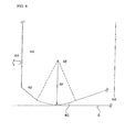
- a cutting edge is constructed at an intersection line of the rake face and flank face and is generally comprised of a major cutting edge, a corner such as a round corner and a chamfer corner, and a minor cutting edge.
- An arrangement of these portions is shown in Figure 8.
- Figure 8 is an enlarged view of the cutting edge at an insert which is carried by a rotating cutting tool such as a milling cutter.
- the milling cutter rotates around the center axes 6B and moves to feed direction 6A (to left in the figure).
- the cutting edge which mainly cuts the work-piece facing the 6A direction is called major cutting edge 4A
- minor cutting edge 4C The cutting edge which mainly cuts finished surface 6 (milled bottom surface)
- the major cutting edge 4A and minor cutting edge 4C are occasionally directly connected, generally however there is a corner 4D between the main cutting edge 4A and minor cutting edge 4C.
- corner 4D liner chamfer as shown in Figure 8 and arc shaped round corner are available.
- the arc portion disclosed in this invention is provided at minor cutting edge 4C.
- This arc has a center 4E, which is the 6B side from the major cutting edge 4A and radius 4F above the finished surface 6, and connects with the corner 4D.
- a minor cutting edge is formed into arc shaped, in other words, a wholly arc shaped minor cutting edge is preferable and a partially arc shaped minor cutting edge is also preferable.
- the radius of the arc is in the range of 10 mm or more to 500 mm or less, preferably in the range of 200 mm or more to 500mm or less.
- the radius is shorter than 10 mm, sharpness decreases and burrs form. Contrarily when the radius is over 500 mm, there is no difference in the linear minor cutting edge, and it is difficult to improve the surface roughness of the finished surface.
- the curvature of the ridge at the wiping edge is in the range of 0.1 ⁇ m or more to 3 ⁇ m or less.
- the curvature is defined as the radius of the cross section perpendicular to the ridge of the cutting edge, which is formed at the intersection line of the rake face and flank face.
- a high quality cutting edge is essential.
- PCD is used as the cutting edge
- the cutting edge made of a single crystal diamond provides higher performance than PCD because a single crystal diamond does not have such drawbacks.
- the insert with a curvature smaller than 0.1 ⁇ m is too expensive and liable to chip, therefore the insert is unsuitable for a rotating cutting tool such as a face milling insert.
- the curvature is preferable in the range of 0.1 ⁇ m to 3 ⁇ m.
- the unevenness of the ridge at a wiping edge is preferable in the range of 0.1 ⁇ m or more to 3 ⁇ m or less.
- the unevenness at the ridge of the wiping edge is the difference between the highest projected portion and lowest recessed portion at the wiping edge and the neighborhood around the wiping edge which contributes to cutting.
- the unevenness at the ridge of the wiping edge In order to improve the smoothness on the work-piece, it is necessary to decrease the unevenness at the ridge of the wiping edge, because the shape of the ridge at a wiping edge is copied to a work-piece. It is too costly to obtain unevenness at the ridge of a wiping edge smaller than 0.1 ⁇ m, because precious machining is necessary.
- the unevenness at the ridge of the wiping edge is larger than 3 ⁇ m the unevenness decreases the smoothness of the work-piece, because the wiping edge is copied to the work-piece. Therefore the unevenness at the ridge of the wiping edge is preferable from 0.1 ⁇ m to 3 ⁇ m.
- the rotating cutting tools include milling cutter (including end mill), drill and reamer.
- the insert can be used as an indexable insert, which is carried by the body of said rotating cutting tool. It is especially preferable to use the insert as a face milling cutter which is used in the field of easily forming burrs.
- a milling cutter using indexable inserts generally carried 4 to 24 inserts.
- a milling cutter of the present invention uses 1 or 2 inserts of single crystal diamond as a cutting edge among 4 to 24 inserts. For example, a milling cutter which uses fewer than 10 inserts, held one insert having a cutting edge of single crystal diamond. A milling cutter using more than 10 inserts held two inserts having a cutting edge of single crystal diamond.
- the rake angle of the axis direction is in the range of about 10 degrees to -20 degrees in the insert having a cutting edge of a single crystal diamond. More preferably it is in the range of about 5 degrees to -10 degrees and most preferable at around 0 degree to maintain the sharpness of the cutting edge. It is preferable that the flank angle is in the range of about 3 degrees to 5 degrees. These angle limitations make it possible to enlarge an angle between the rake face and flank face, and strengthen the cutting edge and repress the chipping of the inserts. When the cutting speed is high such as 5000 m/ min, the rake face is preferably in the range of -5 degrees to -10 degrees to prevent chipping.
- the meaning of the rake angle of the axis direction is not an angle of the insert itself but a practical rake angle of inserts carried in the milling cutter. It is preferable that a rake angle of the standalone insert have a negative angle and the practical rake angle be around 0 degree.
- a high hard material other than single crystal diamond means a cemented carbide, a cermet, cubic boron nitride sintered body and diamond sintered body.
- an insert made of high hard material have a rake angle of axis direction within the range of about 8 degrees to 20 degrees, flank angle within the range of 5 degrees to 10degrees. These preferable angles make it possible to achieve good sharpness of the cutting edge.
- a cutting edge of single crystal diamond projects in the range of 0.01 mm or more to 0.05 mm or less in the direction of the rotating axis.
- the surface which is cut by the minor cutting edge of a high hard material is then cut preciously by the minor cutting edge of a single crystal diamond in this milling cutter (minor cutting edge is wiping edge). Therefore an extremely smooth surface is obtained and the occurrence of burrs is prevented on the milled surface of the work-piece.
- the cutting edge of high hard material projects more than the cutting edge of a single crystal diamond in the radius direction which is perpendicular to the rotating axis. Since the work-piece in the feed direction is cut by the major cutting edge of a high hard material and is not cut by the major cutting edge of a single crystal diamond in this milling cutter, chipping of the single crystal diamond is prevented. It is unnecessary to strictly define the extent of the projection.
- the cutting edge of the high hard material projects so that the major cutting edge of a single crystal diamond does not contact the work-piece.
- the present invented cutting tool is not limited to the material of the work-piece, but is suitable for cutting non-ferrous metals.
- the present invented cutting tool is available for aluminum alloy, high -silicon -aluminum alloy, Metal Matrix Composites (MMC), Fiber Reinforced Plastic (FRP), silicon crystal, germanium crystal and cooper, etc.
- MMC Metal Matrix Composites
- FRP Fiber Reinforced Plastic
- a cutting method using a single crystal diamond tool is characterized in that its depth of cut is in the range of 0.01 mm or more to 0.05 mm or less .
- the depth of cut is smaller than 0.01 mm, it is difficult to cut into a smooth finished surface, because of insufficient cutting depth.
- the depth of cut is larger than 0.05 mm, chipping of the cutting edge is liable to occur.
- the depth of cut means the distance between the surface to be cut and the finished surface. Therefore the method defined by the depth of cut being in the range of 0.01 or more to 0.05 mm or less applicable to the cutting tool having one cutting edge. When the method is applied to the cutting tool having more than one cutting edge, all of the flat cutting edges should substantially project uniformly.
- the invented cutting tool has one or more cutting edges of single crystal diamond and cutting edge of high hard material, and the former cutting edges project against the latter in the axis direction. It is preferable that the projection length be in the range of 0.01 mm or more to 0.05 mm or less and distance between surface to be cut and finished surface may be more than 0.05 mm or more. It is essential in this invention that the practical depth of cut which is cut only by the cutting edge of a single crystal diamond is in the range of 0.01 mm or more to 0.05 mm or less.
- High cutting speed is preferable such as faster than 500 m/min, especially faster than 1000 m/min. Such high cutting speed decreases cutting resistance, and therefore maintains remarkable practical use.
- the upper limit of cutting speed is about 6000 m/min considering the durability of the cutting edge.
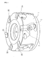
- FIG 1 is a perspective view of an embodiment of a milling cutter of the invention.
- This face milling cutter is composed of a ring shaped body 1 which held plurality of locating pieces 2 made of steel and each locating case 2 fixes the cutting insert 3.
- the insert 3 is mainly made of cemented carbide and the cutting edge only is made from different material.
- the cutting edge of one among 6 inserts is composed of a single crystal diamond 3A, and the remainders of five inserts are composed of PCD 3B in Figure 1.
- Figure 2 shows an invented insert, the cutting edge of which is composed of single crystal diamond.
- Figure 2 (A) is a top view of an invented insert
- Figure 2 (B) is a side view seen from the upper side of Figure 2 (A)
- Figure 2 (C) is a side view seen from the right side of Figure 2 (A)
- Figure 2 (D) is an enlarged view of the cutting edge made of a single crystal diamond 3A.
- the single crystal diamond 3A is united with the substrate of cemented carbide 3C as a cutting edge to form the insert 3.
- the first minor cutting edge (wiping edge ) 4C has an arc shaped portion which has a center at the left side of the first minor cutting edge 4C in Figure 2 (D) and a radius of 300 mm in insert 3.
- Step 3E is provided to adjust a single crystal diamond 3A on the top surface of the cemented carbide substrate.
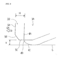
- FIG. 3 shows a rotating locus of single crystal diamond cutting edge lies on a rotating locus of polycrystalline diamond cutting edge in Figure 3 for explanation.
- the vertical direction is a rotating axis direction
- the horizontal direction is a radius direction in Figure 3.
- An arrow 6A in Figure 3 shows the feed direction of the milling cutter.
- the cutting edge of single crystal diamond (chain line ) is composed of main cutting edge 4A, round corner 4B and wiping edge 4C (the first minor cutting edge ) to form a finished surface.
- the wiping edge is an arc shaped portion among these.
- a cutting edge (solid line) of PCD comprises main cutting edge 5A, chamfer corner 5B and linear flat cutting edge 5C (the first minor cutting edge ).
- the wiping edge 4C of a single crystal diamond projects from the cutting edge 5C of PCD in the rotating axis direction.
- the length of projection V is from 0.01 mm to 0.05 mm. Therefore, the finished surface of the work-piece is cut by wiping edge 4C made of a single crystal diamond.
- the main cutting edge 5A made of PCD projects from the main cutting edge 4A made of a single crystal diamond in the radius direction (feed direction).
- the length of projection is 1 mm. Therefore the cutting in the tool feed direction is carried out by the main cutting edge 5A made of PCD, and main cutting edge 4A made of a single crystal diamond does not contribute.
- the PCD insert is used as the main cutting edge which mainly produces chips, and single crystal diamond which is suitable for precision machining is used as the wiping edge which mainly cuts the finished surface.
- the wiping edge makes it possible to prevent chipping and the occurrence of burrs, and therefore to form a super finished surface.
- the surface roughness of the finished surface, the existence or nonexistence of burrs and shiny were investigated by cutting using the invented milling cutter and prior milling cutters.
- three kinds of milling cutters of the following constructions are examined under the following cutting condition.
- a single crystal diamond insert which was used in this test was produced by the process described below.
- Figure 6 is an enlarged photograph of the cutting edge made of a single crystal diamond after the completion of the above process. The cutting edge was observed from the vertical direction to the rake face in Figure 6, and the black upper portion is the cutting edge. Chipping is not found at the cutting edge, and it is observed that unevenness at the ridge of the cutting edge is at most 3 ⁇ m as shown in Figure 6.
- Figure 7 shows the profile of the vertical cross section to the ridge of the cutting edge.
- the oblique line on the left side ascending to the right is a rake face and the oblique line on the right side descending to right is a flank face and the arc at the center is the ridge of the cutting edge. It was confirmed that the curvature is 1 ⁇ m at the ridge of the cutting edge.
- Comparative Example 1 As clearly shown in the Table, the surface roughness of Comparative Example 1 is the most rough and is not shiny at the finished surface, but burrs remain comparatively small. The surface roughness is considerably improved in Comparative Example 2 because the wiper insert was used. Because a PCD was used as the wiper insert having an arc shaped wiping edge, however, sharpness decreased and large burrs remained. On the other hand, because Example 1 used a wiper insert made of single crystal diamond, an extremely smooth and shiny super finished surface was obtained. Also burrs were not observed at all.
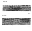
- Figure 4 shows the measurement results of the finished surface roughness.
- Figure 4 (A) is the surface roughness of Example 1
- Figure 4 (B) is the surface roughness of Comparative Example 2.
- the finished surface of Example 1 is cleary smoother than Comparative Example 2.
- the arc shape of the wiper insert was copied to the finished surface almost the same as in example 1, showing that the cutting edge of single crystal diamond has good sharpness.
- Ra in the Figure is arithmetic mean roughness defined in Japanese Industrial Standard (JIS) Number 0601
- Rmax is maximum height excluding swell height
- Rz is mean roughness of ten points defined in JIS 0601
- Rt is maximum roughness excluding swell height defined in JIS 0601.
- the surface roughness curve is enlarged fifty times in the horizontal direction and ten thousand times in the vertical direction.
- the effects were examined using a wiper insert made of a trial single crystal diamond.
- a work-piece of ADC12 was cut by an insert of the above Comparative Example 2 in the same manner as test 1, and the side surface which is vertical to the first finished surface was photographed from the direction of the edge line of the cutting surface.
- a milling cutter was then prepared in which a wiper insert having a single crystal diamond cutting edge and a valance insert having no cutting edge were held at the opposite side of the body. Part of the balance insert only balanced with a wiper insert of a single crystal diamond, and did not cut.
- the first finished surface was again cut by this milling cutter under the condition of 0.05 mm depth of cut.
- the surface which is vertical to the obtained second finished surface was photographed from the direction of the edge line of the cutting surface, and the effects of using a wiper insert made of a single crystal diamond was confirmed.
- Cutting tests were carried out in the same manner as test 1, changing the radius of the arc shaped cutting edge in Example 1.
- Six inserts were prepared with radii of 5, 10, 100, 300, 500, 1000 mm.
- Cutting speed was 3000 m/min.
- the finished surface had no burrs and had a super finished surface with no cloudiness, when using wiper inserts having radii of 10, 100, 300 and 500 mm at the arc shaped portion.
- the finished surface had many burrs and was not shiny when using a wiper insert having a radius of 5 mm at the arc shaped portion.
- the finished surface had small burrs, and was not shiny, which was far from a super finished surface.
- Cutting tests were carried out in the same manner as test 1, changing the projection of the wiping edge of the wiper insert in the direction of the rotating axis. Three projection lengths of 0.005, 0.03 and 0.07 mm were used. Cutting speed was 500 m/min.
- the cutting edge is made of single crystal diamond and has a specific arc shaped portion at the first minor cutting edge.
- the advantage of the results is that the occurrence of burrs can be prevented and a super finished surface achieved. Since a rotating cutting tool of the present invention uses both cutting edges made of the above single crystal diamond and of high hard material other than single crystal diamond, the construction prevents excess cutting force to the cutting edge of the single crystal diamond at cutting, burrs occurrence and realization of super finished surface.
- the depth of the cut is specified in the present cutting method invention, the depth prevents chipping of the cutting edge despite being made of brittle single crystal diamond.
- the rotating cutting tool of the present invention has the advantages of achieving a super finished surface and preventing the occurrence of burrs in the cutting of precious such as an aluminum alloy. Therefore it is possible to omit the process of removing burrs.
Landscapes
- Engineering & Computer Science (AREA)
- Mechanical Engineering (AREA)
- Milling Processes (AREA)
- Cutting Tools, Boring Holders, And Turrets (AREA)
Abstract
The present invention provides a cutting insert, a rotating cutting tool
holding said cutting insert and a cutting method using the tool which is able to
prevent the occurrence of burrs and to cut a smooth finished surface.
In a rotating cutting tool which carries a plurality of cutting inserts, at least
one insert is made of single crystal diamond 3A, and the minor cutting edge of
the insert has an arc shaped portion whose radius is in the range of 10 mm or
more to 500 mm or less.
A high hard material other than single crystal diamond, for example PCD 3B,
is used for the remainder of the cutting inserts.
It is preferable that a cutting edge of single crystal diamond 3A be projected
to the rotating axis direction in the range of 0.01 mm or more to 0.05 mm or
less, compared with the cutting edges of high hard material.
Description
The invention pertains to an insert for a rotating cutting tool, a rotating
cutting tool and cutting method using the rotating cutting tool that provide
improved performance features for non ferrous metals such as aluminum cast
alloys.
A sintered diamond body (PCD) tool has been widely used in cutting
non ferrous metal, especially aluminum alloy for automotive parts and
electronics parts. For example as shown in Figure 1 a face milling cutter having
a ring shaped body 1 which holds a plurality of locating pieces, each locating
piece carrying an insert 3 is well known. Almost all of an insert 3 is composed of
cemented carbide and PCD is only used at the cutting edge. All the cutting
edges of the insert 3 are made of PCD.
A cutting edge of an insert has an ordinary wiping edge (the first minor
cutting edge), and each insert is held by a means of uniform projection to the
rotating axis direction. When a high accurate finished surface is required, a
face milling cutter in which some of the inserts are projected to the rotating
axes direction compared with other inserts is known (Japanese Patent Laying-Open
No. Tokukaihei 8-309612). At that time, a wiping edge with a gentle arc
cutting edge has often been used.
As described above, the rotating cutting tool holding inserts whose
cutting edges are made of PCD has mainly been used for milling such as
aluminum die casting alloy, because PCD possesses appropriate hardness and
toughness. In particular, a wiper insert with an arc shaped cutting edge is often
used to improve the bottom surface roughness in the finishing machining
process. When an arc shaped cutting edge is used, the unevenness of the
finished surface decreases and smoothness of the surface is improved. However
since the contact length between a work-piece and a cutting edge increases,
cutting resistance increases and burrs tend to develop. The development of
burrs causes an increase in the manufacturing process to remove the burrs and
an increase in the production cost.
To inhibit the development of burrs, a sharp cutting edge is necessary to
improve the cut. Since PCD diamond is made by sintering diamond particles
with binder, it is impossible to make a cutting edge with a curvature that is
smaller than the diameter of the diamond particles (about 5-20 µm).
Therefore it is impossible to inhibit the development of burrs using PCD.
When cutting high ductile material such as an aluminum die casting
alloy, a shape of a cutting edge is copied to the work-piece. Therefore small
unevenness of the ridges at the cutting edge is required to machine a smooth
finished surface.
However since PCD is produced by sintering diamond particle with
binder, diamond particles fall off from the PCD at the polishing cutting edge.
Therefore the cutting edge of PCD decreases the smoothness of the finished
surface because the unevenness of the ridges at the cutting edge inevitably is
the same as the diameter of the diamond particle.
Therefore the object of the present invention is to provide such an
insert for a rotating cutting tool, a rotating cutting tool which holds the insert
and cutting method as most effectively prohibiting the development of burrs
and which forms a smooth finished surface on the work-piece.
The present invention accomplishes the above objects by using at least
one insert, among a plurality of inserts held by a rotating tool, having a cutting
edge with a defined shaped single crystal diamond.
A cutting edge which at least contributes to cutting is single crystal
diamond in this invented insert. A wiping edge provided at the cutting edge has
an arc shaped portion and radius of said arc being from 10 mm or more to 500
mm or less. Regarding a rotating cutting tool carrying a plurality of inserts, the
invented tool uses at least one insert having a cutting edge made of a single
crystal diamond and having a defined arc shaped wiping edge. The
characteristic of this invention is that the cutting edge of the remainding
inserts are made of a high hard material other than single diamond.
A large single crystal diamond is considered for use as a material for a
sharp cutting edge to prevent the occurrence of burrs. In a single crystal
diamond, it is easy to form a sharp cutting edge (at a tip of the cutting edge)
with sufficiently small curvature compared with PCD, because contrary to PCD,
diamond particles do not fall out partially from a single crystal diamond. Also it
is possible to form a sufficiently smooth ridge at the cutting edge compared
with PCD. However a single crystal diamond is a material which is liable to
brittle fracture. On the other hand, a rotating cutting was generally
intermittent cutting, which impacted intermittently against a cutting edge.
Therefore, if a single crystal diamond was used as a cutting edge material for
an insert in the prior rotating cutting tool, the insert could not be used, because
chipping occurred by impact at a cutting edge when metal material for
structural use such as aluminum die casting alloy was cut. A single crystal
diamond therefore was used for turning, which was continuous cutting and did
not impact a cutting edge such as forming a lens made of ZnSe for a laser
optical part. The application was extremely limited in the cutting fields and
also the cutting condition was limited to a very shallow depth of cut.
The present inventors have found that the occurrence of burrs could be
prevented and the improvement of smoothness of the finished surface were
obtained provided that a definite arc shaped portion is formed at the cutting
edge of the single crystal diamond. In particular, the present inventors have
found that using two kinds of inserts, one having said defined arc portion
formed at the cutting edge of said single crystal diamond and the other having
a cutting edge made of high hard material other than a single crystal diamond,
has following advantages. The cutting edge made of high hard material
prevents excess intermittent impact to the single crystal diamond, the invented
cutting tool makes it possible to prevent the occurrence of burrs and to obtain
an extremely smooth finished surface in milling aluminum alloy.
The present invention is explained in detail hereinafter.
Both a natural single crystal diamond and synthetic single crystal diamond
are available. A synthetic single crystal diamond is preferable since synthetic
diamond has small deviation in quality, well-proportioned shape, high strength
and high heat conductivity. In particular, a diamond that includes a small
amount of nitrogen and boron is preferable. For example, a I b type single
crystal diamond including nitrogen 20 wt p.p.m. or more (Produced by
Sumitomo Electric Industries Ltd.: Registered Trademark: SUMI-CRYSTAL )
and a II a type single crystal diamond including nitrogen less than 20 wt.
p.p.m.(Produced by Sumitomo Electric Industries Ltd. Registered Trademark:
SUMI-CRYSTAL TYPE II) are both available.
When a single crystal diamond is used as a cutting edge which at least
contributes to cutting, any direction is available, but the (110) surface is
preferable because the surface direction has high chipping strength.
Instead of using single diamond crystal, chemical vapor deposition
(CVD) diamond which does not include binder is also available.
A cutting edge is constructed at an intersection line of the rake face and
flank face and is generally comprised of a major cutting edge, a corner such as a
round corner and a chamfer corner, and a minor cutting edge. An arrangement
of these portions is shown in Figure 8. Figure 8 is an enlarged view of the
cutting edge at an insert which is carried by a rotating cutting tool such as a
milling cutter. The milling cutter rotates around the center axes 6B and moves
to feed direction 6A (to left in the figure). The cutting edge which mainly cuts
the work-piece facing the 6A direction is called major cutting edge 4A, and the
cutting edge which mainly cuts finished surface 6 (milled bottom surface) is
called minor cutting edge 4C. The major cutting edge 4A and minor cutting
edge 4C are occasionally directly connected, generally however there is a corner
4D between the main cutting edge 4A and minor cutting edge 4C. Regarding
the corner 4D, liner chamfer as shown in Figure 8 and arc shaped round corner
are available. The arc portion disclosed in this invention is provided at minor
cutting edge 4C. This arc has a center 4E, which is the 6B side from the major
cutting edge 4A and radius 4F above the finished surface 6, and connects with
the corner 4D. A minor cutting edge is formed into arc shaped, in other words, a
wholly arc shaped minor cutting edge is preferable and a partially arc shaped
minor cutting edge is also preferable.
The radius of the arc is in the range of 10 mm or more to 500 mm or less,
preferably in the range of 200 mm or more to 500mm or less. When the radius
is shorter than 10 mm, sharpness decreases and burrs form. Contrarily when
the radius is over 500 mm, there is no difference in the linear minor cutting
edge, and it is difficult to improve the surface roughness of the finished surface.
It is preferable that the curvature of the ridge at the wiping edge is in
the range of 0.1 µm or more to 3 µm or less. The curvature is defined as the
radius of the cross section perpendicular to the ridge of the cutting edge, which
is formed at the intersection line of the rake face and flank face.
To obtain a finished surface with few burrs, a high quality cutting edge
is essential. However when PCD is used as the cutting edge, it is impossible to
form a curvature at a cutting edge smaller than the extent of the diamond
particle (5-20 µm ), because an included diamond particle falls off as a particle
unit. On the other hand, the cutting edge made of a single crystal diamond
provides higher performance than PCD because a single crystal diamond does
not have such drawbacks. The insert with a curvature smaller than 0.1 µm is
too expensive and liable to chip, therefore the insert is unsuitable for a rotating
cutting tool such as a face milling insert. On the other hand, when the
curvature is too large, there is no advantage over the PCD. Therefore the
curvature is preferable in the range of 0.1 µm to 3 µm.
The unevenness of the ridge at a wiping edge is preferable in the range
of 0.1 µm or more to 3 µm or less. The unevenness at the ridge of the wiping
edge is the difference between the highest projected portion and lowest
recessed portion at the wiping edge and the neighborhood around the wiping
edge which contributes to cutting.
In order to improve the smoothness on the work-piece, it is necessary to
decrease the unevenness at the ridge of the wiping edge, because the shape of
the ridge at a wiping edge is copied to a work-piece. It is too costly to obtain
unevenness at the ridge of a wiping edge smaller than 0.1 µm, because precious
machining is necessary. When the unevenness at the ridge of the wiping edge is
larger than 3 µm the unevenness decreases the smoothness of the work-piece,
because the wiping edge is copied to the work-piece. Therefore the unevenness
at the ridge of the wiping edge is preferable from 0.1 µm to 3 µm.
The rotating cutting tools include milling cutter (including end mill),
drill and reamer. The insert can be used as an indexable insert, which is carried
by the body of said rotating cutting tool. It is especially preferable to use the
insert as a face milling cutter which is used in the field of easily forming burrs.
It is preferable that there are the fewest possible number of inserts
having cutting edge of single crystal diamond to decrease the production cost.
Despite there being few inserts having a cutting edge of single crystal diamond
in a rotating cutting tool, the tool accomplishes the object of the present
invention that is, to prevent the occurrence of burrs and to finish a smooth
work-piece surface. A milling cutter using indexable inserts generally carried 4
to 24 inserts. A milling cutter of the present invention uses 1 or 2 inserts of
single crystal diamond as a cutting edge among 4 to 24 inserts. For example, a
milling cutter which uses fewer than 10 inserts, held one insert having a
cutting edge of single crystal diamond. A milling cutter using more than 10
inserts held two inserts having a cutting edge of single crystal diamond.
It is preferable that the rake angle of the axis direction is in the range
of about 10 degrees to -20 degrees in the insert having a cutting edge of a
single crystal diamond. More preferably it is in the range of about 5 degrees to
-10 degrees and most preferable at around 0 degree to maintain the sharpness
of the cutting edge. It is preferable that the flank angle is in the range of about
3 degrees to 5 degrees. These angle limitations make it possible to enlarge an
angle between the rake face and flank face, and strengthen the cutting edge
and repress the chipping of the inserts. When the cutting speed is high such as
5000 m/ min, the rake face is preferably in the range of -5 degrees to -10
degrees to prevent chipping.
The meaning of the rake angle of the axis direction is not an angle of
the insert itself but a practical rake angle of inserts carried in the milling
cutter. It is preferable that a rake angle of the standalone insert have a
negative angle and the practical rake angle be around 0 degree.
A high hard material other than single crystal diamond means a
cemented carbide, a cermet, cubic boron nitride sintered body and diamond
sintered body.
It is preferable that an insert made of high hard material have a rake
angle of axis direction within the range of about 8 degrees to 20 degrees, flank
angle within the range of 5 degrees to 10degrees. These preferable angles make
it possible to achieve good sharpness of the cutting edge.
Preferably a cutting edge of single crystal diamond projects in the range
of 0.01 mm or more to 0.05 mm or less in the direction of the rotating axis. The
surface which is cut by the minor cutting edge of a high hard material is then
cut preciously by the minor cutting edge of a single crystal diamond in this
milling cutter (minor cutting edge is wiping edge). Therefore an extremely
smooth surface is obtained and the occurrence of burrs is prevented on the
milled surface of the work-piece.
Furthermore, the cutting edge of high hard material projects more than
the cutting edge of a single crystal diamond in the radius direction which is
perpendicular to the rotating axis. Since the work-piece in the feed direction is
cut by the major cutting edge of a high hard material and is not cut by the
major cutting edge of a single crystal diamond in this milling cutter, chipping of
the single crystal diamond is prevented. It is unnecessary to strictly define the
extent of the projection. The cutting edge of the high hard material projects so
that the major cutting edge of a single crystal diamond does not contact the
work-piece.
The present invented cutting tool is not limited to the material of the
work-piece, but is suitable for cutting non-ferrous metals. The present invented
cutting tool is available for aluminum alloy, high -silicon -aluminum alloy,
Metal Matrix Composites (MMC), Fiber Reinforced Plastic (FRP), silicon
crystal, germanium crystal and cooper, etc.
A cutting method using a single crystal diamond tool is characterized in
that its depth of cut is in the range of 0.01 mm or more to 0.05 mm or less .
When the depth of cut is smaller than 0.01 mm, it is difficult to cut into a
smooth finished surface, because of insufficient cutting depth. When the depth
of cut is larger than 0.05 mm, chipping of the cutting edge is liable to occur.
Generally the depth of cut means the distance between the surface to be cut
and the finished surface. Therefore the method defined by the depth of cut
being in the range of 0.01 or more to 0.05 mm or less applicable to the cutting
tool having one cutting edge. When the method is applied to the cutting tool
having more than one cutting edge, all of the flat cutting edges should
substantially project uniformly. As described hereafter, the invented cutting
tool has one or more cutting edges of single crystal diamond and cutting edge of
high hard material, and the former cutting edges project against the latter in
the axis direction. It is preferable that the projection length be in the range of
0.01 mm or more to 0.05 mm or less and distance between surface to be cut and
finished surface may be more than 0.05 mm or more. It is essential in this
invention that the practical depth of cut which is cut only by the cutting edge of
a single crystal diamond is in the range of 0.01 mm or more to 0.05 mm or less.
High cutting speed is preferable such as faster than 500 m/min,
especially faster than 1000 m/min. Such high cutting speed decreases cutting
resistance, and therefore maintains remarkable practical use. The upper limit
of cutting speed is about 6000 m/min considering the durability of the cutting
edge.
Hereunder, preferable embodiment of the invention is described.
Figure 1 is a perspective view of an embodiment of a milling cutter of
the invention. This face milling cutter is composed of a ring shaped body 1
which held plurality of locating pieces 2 made of steel and each locating case 2
fixes the cutting insert 3. The insert 3 is mainly made of cemented carbide and
the cutting edge only is made from different material. The cutting edge of one
among 6 inserts is composed of a single crystal diamond 3A, and the
remainders of five inserts are composed of PCD 3B in Figure 1.
Figure 2 shows an invented insert, the cutting edge of which is
composed of single crystal diamond. Figure 2 (A) is a top view of an invented
insert, Figure 2 (B) is a side view seen from the upper side of Figure 2 (A),
Figure 2 (C) is a side view seen from the right side of Figure 2 (A) and Figure 2
(D) is an enlarged view of the cutting edge made of a single crystal diamond 3A.
The single crystal diamond 3A is united with the substrate of cemented carbide
3C as a cutting edge to form the insert 3. The first minor cutting edge (wiping
edge ) 4C has an arc shaped portion which has a center at the left side of the
first minor cutting edge 4C in Figure 2 (D) and a radius of 300 mm in insert 3.
The arc portion provided at the minor cutting edge 4C and linear portion is tied
together at 3D (Referring to Figure 2 (B) and Figure 2 (C)), which emerges at
the polishing step of the production. Step 3E is provided to adjust a single
crystal diamond 3A on the top surface of the cemented carbide substrate.
Further a rotating locus of single crystal diamond cutting edge lies on a
rotating locus of polycrystalline diamond cutting edge in Figure 3 for
explanation. The vertical direction is a rotating axis direction, and the
horizontal direction is a radius direction in Figure 3. An arrow 6A in Figure 3
shows the feed direction of the milling cutter.
The cutting edge of single crystal diamond (chain line ) is composed of
main cutting edge 4A, round corner 4B and wiping edge 4C (the first minor
cutting edge ) to form a finished surface. The wiping edge is an arc shaped
portion among these.
On the other hand, a cutting edge (solid line) of PCD comprises main
cutting edge 5A, chamfer corner 5B and linear flat cutting edge 5C (the first
minor cutting edge ).
The wiping edge 4C of a single crystal diamond projects from the
cutting edge 5C of PCD in the rotating axis direction. The length of projection V
is from 0.01 mm to 0.05 mm. Therefore, the finished surface of the work-piece is
cut by wiping edge 4C made of a single crystal diamond. The main cutting edge
5A made of PCD projects from the main cutting edge 4A made of a single
crystal diamond in the radius direction (feed direction). The length of projection
is 1 mm. Therefore the cutting in the tool feed direction is carried out by the
main cutting edge 5A made of PCD, and main cutting edge 4A made of a single
crystal diamond does not contribute.
Thus the PCD insert is used as the main cutting edge which mainly
produces chips, and single crystal diamond which is suitable for precision
machining is used as the wiping edge which mainly cuts the finished surface.
The wiping edge makes it possible to prevent chipping and the occurrence of
burrs, and therefore to form a super finished surface.
The surface roughness of the finished surface, the existence or nonexistence
of burrs and shiny were investigated by cutting using the invented milling
cutter and prior milling cutters. Here, three kinds of milling cutters of the
following constructions are examined under the following cutting condition.
A single crystal diamond insert which was used in this test was
produced by the process described below.
Figure 6 is an enlarged photograph of the cutting edge made of a single
crystal diamond after the completion of the above process. The cutting edge
was observed from the vertical direction to the rake face in Figure 6, and the
black upper portion is the cutting edge. Chipping is not found at the cutting
edge, and it is observed that unevenness at the ridge of the cutting edge is at
most 3 µm as shown in Figure 6.
Figure 7 shows the profile of the vertical cross section to the ridge of the
cutting edge. In the curve of Figure 7, the oblique line on the left side ascending
to the right is a rake face and the oblique line on the right side descending to
right is a flank face and the arc at the center is the ridge of the cutting edge. It
was confirmed that the curvature is 1 µm at the ridge of the cutting edge.
The results of the test are shown in Table 1
| Surface roughness | Burr | Surface condition | ||
| Comparative Example 1 | Six PCD inserts having linear flat cutting edges | × Rz:1.13 µm | Δ about 0.05 mm height | × not shiny |
| Comparative Example 2 | Five PCD inserts having linear flat cutting edges and PCD insert having wiping edge | ○ Rz:0.48 µm | × about 0.2 mm height | × not shiny |
| Example 1 | Five PCD inserts having linear flat cutting edges and a single crystal diamond insert having wiping edge | RZ:0.3 µm | o ○ 0mm height | o ○ shiny |
As clearly shown in the Table, the surface roughness of Comparative
Example 1 is the most rough and is not shiny at the finished surface, but burrs
remain comparatively small. The surface roughness is considerably improved
in Comparative Example 2 because the wiper insert was used. Because a PCD
was used as the wiper insert having an arc shaped wiping edge, however,
sharpness decreased and large burrs remained. On the other hand, because
Example 1 used a wiper insert made of single crystal diamond, an extremely
smooth and shiny super finished surface was obtained. Also burrs were not
observed at all.
Figure 4 shows the measurement results of the finished surface
roughness. Figure 4 (A) is the surface roughness of Example 1 and Figure 4 (B)
is the surface roughness of Comparative Example 2. The finished surface of
Example 1 is cleary smoother than Comparative Example 2. Also the arc shape
of the wiper insert was copied to the finished surface almost the same as in
example 1, showing that the cutting edge of single crystal diamond has good
sharpness.
The measurement results in Figure 4 were carried out under the
condition of cut off value of 0.8 mm and measurement length of 2 mm. Ra in the
Figure is arithmetic mean roughness defined in Japanese Industrial Standard
(JIS) Number 0601, Rmax is maximum height excluding swell height, Rz is
mean roughness of ten points defined in JIS 0601, Rt is maximum roughness
excluding swell height defined in JIS 0601. The surface roughness curve is
enlarged fifty times in the horizontal direction and ten thousand times in the
vertical direction.
The effects were examined using a wiper insert made of a trial single crystal
diamond. The first, a work-piece of ADC12 was cut by an insert of the above
Comparative Example 2 in the same manner as test 1, and the side surface
which is vertical to the first finished surface was photographed from the
direction of the edge line of the cutting surface. A milling cutter was then
prepared in which a wiper insert having a single crystal diamond cutting edge
and a valance insert having no cutting edge were held at the opposite side of
the body. Part of the balance insert only balanced with a wiper insert of a single
crystal diamond, and did not cut. The first finished surface was again cut by
this milling cutter under the condition of 0.05 mm depth of cut. The surface
which is vertical to the obtained second finished surface was photographed
from the direction of the edge line of the cutting surface, and the effects of using
a wiper insert made of a single crystal diamond was confirmed.
Both results are shown in Figure 5. The side surface of the work-piece
cut by a wiper insert of a single crystal diamond is shown in Figure 5(A), and
the side surface of the work piece cut by Comparative Example 2 is shown in
Figure 5(B). The photographs are taken from the right top side surface with
diagonal illumination on the side surface from above the finished surface. The
lower 2/3 of the photographs are the work-piece and the upper 1/3 are the space
above the finished surface. The white portion at the boundary of the work-piece
and the space of the finished surface, is burrs. The finished surface appears
gray because the finished surface reflects in different direction from the camera.
The burrs appear white as shown in Figure 5(B), because a part reflects at the
uneven burrs, which reaches the camera directly. When comparing both
photographs, it is clear that there are no burrs on the finished surface milled
with the wiper insert made of single crystal diamond.
Cutting tests were carried out in the same manner as test 1, changing the
radius of the arc shaped cutting edge in Example 1. Six inserts were prepared
with radii of 5, 10, 100, 300, 500, 1000 mm. Cutting speed was 3000 m/min.
The finished surface had no burrs and had a super finished surface
with no cloudiness, when using wiper inserts having radii of 10, 100, 300 and
500 mm at the arc shaped portion. On the other hand, the finished surface had
many burrs and was not shiny when using a wiper insert having a radius of 5
mm at the arc shaped portion. Also, when using a wiper insert having a radius
of 1000 mm, the finished surface had small burrs, and was not shiny, which
was far from a super finished surface.
Cutting tests were carried out in the same manner as test 1, changing the
projection of the wiping edge of the wiper insert in the direction of the rotating
axis. Three projection lengths of 0.005, 0.03 and 0.07 mm were used. Cutting
speed was 500 m/min.
Consequently, a good burr-free finished surface was obtained only when
a work-piece was cut by the milling cutter having a projection of 0.03 mm. A
super finished surface was not obtained using a milling cutter having a
projection of 0.005 mm, because of insufficient cutting depth by the single
crystal diamond. A super finished surface was also not obtained using the
milling cutter having a projection of 0.07 mm, because chipping occurred at the
cutting edge of the single crystal diamond.
Cutting tests were carried out in the same manner as test 1, changing the
curvature of the cutting edge. Three curvatures of 0.05, 3 and 3.5 µm were
tested. It was confirmed that the insert having a curvature of 0.1 µm to 3 µ
m did not chip easily, had high quality cutting and low production costs.
Cutting tests were carried out in the same manner as test 1, changing the
unevenness at the ridge of the cutting edge. Three kinds of unevenness at the
ridge of 0.05, 3 and 3.5 µm were tested. It was confirmed that the inserts
having unevenness from 0.1 µm to 3 µm tended not to decreases the
smoothness of the finished surface and were produced at low cost.
As explained above, according to the present invention, the cutting edge
is made of single crystal diamond and has a specific arc shaped portion at the
first minor cutting edge. The advantage of the results is that the occurrence of
burrs can be prevented and a super finished surface achieved. Since a rotating
cutting tool of the present invention uses both cutting edges made of the above
single crystal diamond and of high hard material other than single crystal
diamond, the construction prevents excess cutting force to the cutting edge of
the single crystal diamond at cutting, burrs occurrence and realization of super
finished surface.
Since the depth of the cut is specified in the present cutting method
invention, the depth prevents chipping of the cutting edge despite being made
of brittle single crystal diamond.
In addition, the rotating cutting tool of the present invention has the
advantages of achieving a super finished surface and preventing the occurrence
of burrs in the cutting of precious such as an aluminum alloy. Therefore it is
possible to omit the process of removing burrs.
Claims (7)
- An insert for a rotating cutting tool comprising:a cutting edge of single crystal diamond that at least contributes to cutting;a wiping edge having an arc shaped portion provided at said cutting edge;a radius of said arc being between 10 mm or more and 500 mm or less.
- The insert for a rotating cutting tool of claim 1 wherein a curvature of the ridge at the wiping edge is between 0.1 µm or more and 3 µm or less.
- The insert for a rotating cutting tool of claim 1 wherein unevenness at the ridge of the wiping edge is between 0.1 µm or more and 3 µm or less.
- A rotating cutting tool comprising:a plurality of inserts being carried;the inserts being selected from the inserts for a rotating cutting tool described in claims 1 to 3 ;the remaining inserts being made of high hard material other than single crystal diamond.
- The rotating cutting tool of claim 4 wherein a wiping edge of single crystal diamond projects in the range of 0.01 mm or more to 0.05 mm or less to the rotating axis direction compared with the cutting edges of high hard material inserts.
- The rotating cutting tool of claim 4 or claim 5 wherein the cutting edge made of high hard material other than single crystal diamond projects from that of single crystal diamond in the radius direction.
- A milling method comprising:using a rotating cutting tool selected from claims 4 to 6;cutting depth being substantially in the range of 0.01 mm or more to 0.05 mm or less;said depth is cut only by the cutting edge of single crystal diamond.
Applications Claiming Priority (5)
| Application Number | Priority Date | Filing Date | Title |
|---|---|---|---|
| JP2000329613 | 2000-10-27 | ||
| JP2000329613 | 2000-10-27 | ||
| JP2001284081A JP3378575B2 (en) | 2000-10-27 | 2001-09-18 | Milling cutter |
| JP2001284081 | 2001-09-18 | ||
| PCT/JP2001/009228 WO2002034442A1 (en) | 2000-10-27 | 2001-10-19 | Cutting tip for rotating cutting tool and rotating cutting tool using the tip, and method of machining using the tool |
Publications (2)
| Publication Number | Publication Date |
|---|---|
| EP1332820A1 true EP1332820A1 (en) | 2003-08-06 |
| EP1332820A4 EP1332820A4 (en) | 2010-07-14 |
Family
ID=26602982
Family Applications (1)
| Application Number | Title | Priority Date | Filing Date |
|---|---|---|---|
| EP01974893A Withdrawn EP1332820A4 (en) | 2000-10-27 | 2001-10-19 | CUTTING HEAD FOR ROTARY CUTTING TOOL AND ROTARY CUTTING TOOL USING SAID CUTTING HEAD, AND MACHINING METHOD USING THE SAME |
Country Status (4)
| Country | Link |
|---|---|
| US (1) | US6913424B2 (en) |
| EP (1) | EP1332820A4 (en) |
| JP (1) | JP3378575B2 (en) |
| WO (1) | WO2002034442A1 (en) |
Cited By (1)
| Publication number | Priority date | Publication date | Assignee | Title |
|---|---|---|---|---|
| WO2009147461A1 (en) * | 2008-06-06 | 2009-12-10 | VILMÁNYI, Gábor | Milling tool |
Families Citing this family (33)
| Publication number | Priority date | Publication date | Assignee | Title |
|---|---|---|---|---|
| US7191008B2 (en) | 2001-05-30 | 2007-03-13 | Medtronic, Inc. | Implantable medical device with a dual power source |
| DE10159431B4 (en) * | 2001-12-04 | 2005-10-20 | Mapal Fab Praezision | Tool for finishing surfaces |
| JP4556383B2 (en) * | 2002-11-29 | 2010-10-06 | コニカミノルタホールディングス株式会社 | Processing method of transfer optical surface |
| FR2861002B1 (en) * | 2003-10-15 | 2007-02-23 | Renault Sa | METHOD FOR MACHINING A FACE OF CARTER AND TOOL FOR IMPLEMENTING SUCH A METHOD |
| DE10358568B4 (en) * | 2003-12-15 | 2007-07-19 | Hilti Ag | Tool |
| JP4585243B2 (en) * | 2004-06-30 | 2010-11-24 | 株式会社アライドマテリアル | Single crystal diamond cutting tool for ultra-precision machining |
| TWI411710B (en) * | 2004-09-10 | 2013-10-11 | Carnegie Inst Of Washington | Ultratough cvd single crystal diamond and three dimensional growth thereof |
| JP4723302B2 (en) * | 2005-07-25 | 2011-07-13 | ユニタック株式会社 | Machine reamer |
| DE102005054434B4 (en) * | 2005-11-15 | 2009-09-24 | Kennametal Inc. | Indexable insert with two part bodies |
| US20070173183A1 (en) * | 2006-01-25 | 2007-07-26 | Keene Milford M | Cutting tool with integrated abrasive trimming elements |
| US9079260B2 (en) * | 2007-11-01 | 2015-07-14 | GM Global Technology Operations LLC | Polycrystalline diamond cutting tool with coated body |
| US8702357B2 (en) * | 2009-02-10 | 2014-04-22 | Kennametal Inc. | Multi-piece drill head and drill including the same |
| US8827606B2 (en) * | 2009-02-10 | 2014-09-09 | Kennametal Inc. | Multi-piece drill head and drill including the same |
| US9539652B2 (en) | 2010-04-30 | 2017-01-10 | Kennametal Inc. | Rotary cutting tool having PCD cutting tip |
| DE102010036869A1 (en) | 2010-08-05 | 2012-02-09 | Gühring Ohg | cutting tool |
| US8926237B2 (en) | 2011-07-11 | 2015-01-06 | Kennametal Inc. | Multi-piece twist drill head and twist drill including the same |
| JP2013108173A (en) * | 2011-10-26 | 2013-06-06 | Sumitomo Chemical Co Ltd | Method for manufacturing sputtering target and sputtering target |
| US9114487B2 (en) | 2012-05-29 | 2015-08-25 | Apple Inc. | Components of an electronic device and methods for their assembly |
| US9302334B2 (en) * | 2012-05-29 | 2016-04-05 | Apple Inc. | Cutting tools for cutting curved and complex features |
| KR101476406B1 (en) * | 2012-10-26 | 2014-12-26 | 차인선 | Pcd milling cutter for lens processing |
| EP2740555B1 (en) * | 2012-12-07 | 2016-03-16 | Sandvik Tooling France | Cutting tool for face milling, corresponding method of face milling, cutting insert and tool body |
| FR3003490B1 (en) * | 2013-03-25 | 2015-05-22 | Palumbo Ind | TOOL AND METHOD FOR MILLING A METAL PIECE |
| WO2015129769A1 (en) * | 2014-02-26 | 2015-09-03 | 株式会社タンガロイ | Cutting insert and cutting tool |
| JP6457257B2 (en) * | 2014-12-18 | 2019-01-23 | Dmg森精機株式会社 | Milling tool and machining method using the same |
| JP2017087373A (en) * | 2015-11-13 | 2017-05-25 | 株式会社アライドマテリアル | Rotary Cutting Tool |
| JP2017094467A (en) * | 2015-11-26 | 2017-06-01 | 住友電工ハードメタル株式会社 | Rotating tool |
| JP6817717B2 (en) * | 2016-04-07 | 2021-01-20 | 三菱マテリアル株式会社 | Milling cutters, cutting inserts and milling methods |
| EP3321017B1 (en) * | 2016-11-09 | 2020-06-03 | Sandvik Intellectual Property AB | Milling tool |
| JP7214386B2 (en) * | 2018-07-13 | 2023-01-30 | 株式会社アライドマテリアル | rotary cutting tool |
| JP7243001B2 (en) * | 2019-03-29 | 2023-03-22 | 三菱マテリアル株式会社 | milling tool |
| WO2020231047A1 (en) * | 2019-05-15 | 2020-11-19 | Taegutec Ltd. | Cutting tool assembly |
| JP6765477B1 (en) | 2019-06-07 | 2020-10-07 | 株式会社牧野フライス製作所 | Milling cutter |
| IT202100033122A1 (en) * | 2021-12-30 | 2023-06-30 | Fiudi S R L | Scraper insert for rotary face milling cutter |
Family Cites Families (17)
| Publication number | Priority date | Publication date | Assignee | Title |
|---|---|---|---|---|
| CH595200A5 (en) * | 1975-05-16 | 1978-02-15 | Kistler Instrumente Ag | |
| JPS5950449B2 (en) * | 1976-09-30 | 1984-12-08 | ダイジエツト工業株式会社 | Front milling cutter |
| JPS57121412A (en) * | 1981-01-20 | 1982-07-28 | Komatsu Ltd | Milling cutter |
| JPS5950449A (en) | 1982-09-17 | 1984-03-23 | Ricoh Co Ltd | Electrostatic image developing toner and its manufacture |
| US4512426A (en) * | 1983-04-11 | 1985-04-23 | Christensen, Inc. | Rotating bits including a plurality of types of preferential cutting elements |
| JPH01132317A (en) | 1987-11-17 | 1989-05-24 | Mitsubishi Heavy Ind Ltd | Cultivator |
| JPH01132317U (en) * | 1988-03-07 | 1989-09-08 | ||
| US4930945A (en) * | 1988-05-20 | 1990-06-05 | Mitsubishi Metal Corporation | Insert rotary cutter |
| US5178645A (en) * | 1990-10-08 | 1993-01-12 | Sumitomo Electric Industries, Ltd. | Cutting tool of polycrystalline diamond and method of manufacturing the same |
| JP2751873B2 (en) | 1994-09-22 | 1998-05-18 | 住友電気工業株式会社 | Indexable insert for milling and milling cutter using the same |
| US5672031A (en) * | 1995-05-12 | 1997-09-30 | Kennametal Inc. | Milling cutter |
| JPH0930118A (en) | 1995-07-18 | 1997-02-04 | Ricoh Co Ltd | Record erasing method and reproducing method for reversible thermosensitive recording medium |
| JP3646827B2 (en) * | 1996-05-20 | 2005-05-11 | Hoya株式会社 | Cutting method of plastic lens |
| JP3544601B2 (en) | 1996-07-30 | 2004-07-21 | 住友電気工業株式会社 | Ultra-precision cutting method for crystalline materials |
| JPH10193204A (en) | 1997-01-09 | 1998-07-28 | Mitsubishi Materials Corp | Thrust cutters and tips for thrust cutters |
| DE60041320D1 (en) * | 1999-11-25 | 2009-02-26 | Sumitomo Electric Industries | Cutting tool made of polycrystalline carbide |
| JP2001300813A (en) * | 2000-02-18 | 2001-10-30 | Sumitomo Electric Ind Ltd | Ball end mill |
-
2001
- 2001-09-18 JP JP2001284081A patent/JP3378575B2/en not_active Expired - Lifetime
- 2001-10-19 US US10/168,678 patent/US6913424B2/en not_active Expired - Lifetime
- 2001-10-19 WO PCT/JP2001/009228 patent/WO2002034442A1/en not_active Ceased
- 2001-10-19 EP EP01974893A patent/EP1332820A4/en not_active Withdrawn
Cited By (3)
| Publication number | Priority date | Publication date | Assignee | Title |
|---|---|---|---|---|
| WO2009147461A1 (en) * | 2008-06-06 | 2009-12-10 | VILMÁNYI, Gábor | Milling tool |
| AT12539U1 (en) * | 2008-06-06 | 2012-07-15 | Vilmanyi Gabor | MILLING TOOL |
| AT12539U8 (en) * | 2008-06-06 | 2012-09-15 | Vilmanyi Gabor | MILLING TOOL |
Also Published As
| Publication number | Publication date |
|---|---|
| WO2002034442A1 (en) | 2002-05-02 |
| US6913424B2 (en) | 2005-07-05 |
| JP2002200518A (en) | 2002-07-16 |
| JP3378575B2 (en) | 2003-02-17 |
| US20030133763A1 (en) | 2003-07-17 |
| EP1332820A4 (en) | 2010-07-14 |
Similar Documents
| Publication | Publication Date | Title |
|---|---|---|
| US6913424B2 (en) | Cutting tip for rotating cutting tool and rotating cutting tool using the tip, and method of machining using the tool | |
| JP2751873B2 (en) | Indexable insert for milling and milling cutter using the same | |
| US6652201B2 (en) | Ball end mill | |
| KR101879258B1 (en) | Negative-type cutting insert, blade-interchangeable rotary cutting tool using same cutting insert, blade-interchangeable rotary cutting tool system, and cutting method | |
| US6612786B1 (en) | Cutting tool of polycrystalline hard sintered material | |
| CN110035851B (en) | cutting tool | |
| EP1226892A2 (en) | Cutting tool | |
| JP6898948B2 (en) | Turning insert | |
| JPH09507438A (en) | Indexable insert for finishing milling and its body | |
| US7607867B2 (en) | Tooling insert with mating surface | |
| US7556456B2 (en) | Mono crystalline diamond cutting tool for ultra precision machining | |
| US5074721A (en) | Metal cutting blade and process for manufacture thereof | |
| JP2005111651A (en) | Tip, milling cutter, and machining method using the same | |
| JP6318579B2 (en) | Insert and insertable ball end mill with insert | |
| US8366359B2 (en) | Method for machining crankshafts and device for carrying out this method | |
| JP2001212703A (en) | Polycrystalline hard sintered compact cutting tool | |
| CN116887938A (en) | Cutting inserts and indexable insert cutting tools | |
| JP2003117717A (en) | Wiper inserts and wiper inserts for rotary cutting tools | |
| JP2022130806A (en) | cutting insert | |
| EP1053814A2 (en) | Cutting tooth | |
| JPH10118824A (en) | Vertical chip and milling cutter with the same | |
| JPH08141817A (en) | Throw-away tip for ball end mill and manufacturing method thereof | |
| JP3805060B2 (en) | Diamond sintered body chip | |
| WO2025197799A1 (en) | Cutting insert and blade-tip-replaceable cutting tool | |
| WO2019166133A1 (en) | Indexable cutting insert |
Legal Events
| Date | Code | Title | Description |
|---|---|---|---|
| PUAI | Public reference made under article 153(3) epc to a published international application that has entered the european phase |
Free format text: ORIGINAL CODE: 0009012 |
|
| 17P | Request for examination filed |
Effective date: 20020626 |
|
| AK | Designated contracting states |
Designated state(s): AT BE CH CY DE DK ES FI FR GB GR IE IT LI LU MC NL PT SE TR |
|
| RBV | Designated contracting states (corrected) |
Designated state(s): AT BE CH DE FR IT LI |
|
| A4 | Supplementary search report drawn up and despatched |
Effective date: 20100610 |
|
| 17Q | First examination report despatched |
Effective date: 20101125 |
|
| STAA | Information on the status of an ep patent application or granted ep patent |
Free format text: STATUS: THE APPLICATION IS DEEMED TO BE WITHDRAWN |
|
| 18D | Application deemed to be withdrawn |
Effective date: 20110629 |