EP1331796A1 - Boítier de téléphone mobile à habillage amovible - Google Patents
Boítier de téléphone mobile à habillage amovible Download PDFInfo
- Publication number
- EP1331796A1 EP1331796A1 EP03290100A EP03290100A EP1331796A1 EP 1331796 A1 EP1331796 A1 EP 1331796A1 EP 03290100 A EP03290100 A EP 03290100A EP 03290100 A EP03290100 A EP 03290100A EP 1331796 A1 EP1331796 A1 EP 1331796A1
- Authority
- EP
- European Patent Office
- Prior art keywords
- shells
- housing according
- housing
- locking means
- plate
- Prior art date
- Legal status (The legal status is an assumption and is not a legal conclusion. Google has not performed a legal analysis and makes no representation as to the accuracy of the status listed.)
- Granted
Links
- 230000000903 blocking effect Effects 0.000 claims description 3
- 238000005192 partition Methods 0.000 description 27
- 235000005921 Cynara humilis Nutrition 0.000 description 7
- 240000002228 Cynara humilis Species 0.000 description 7
- BASFCYQUMIYNBI-UHFFFAOYSA-N platinum Chemical compound [Pt] BASFCYQUMIYNBI-UHFFFAOYSA-N 0.000 description 5
- 206010017577 Gait disturbance Diseases 0.000 description 3
- 238000009434 installation Methods 0.000 description 2
- 238000012423 maintenance Methods 0.000 description 1
- 210000000056 organ Anatomy 0.000 description 1
- 229910052697 platinum Inorganic materials 0.000 description 1
- 238000000926 separation method Methods 0.000 description 1
- 239000007787 solid Substances 0.000 description 1
- 230000001960 triggered effect Effects 0.000 description 1
Images



Classifications
-
- H—ELECTRICITY
- H04—ELECTRIC COMMUNICATION TECHNIQUE
- H04M—TELEPHONIC COMMUNICATION
- H04M1/00—Substation equipment, e.g. for use by subscribers
- H04M1/02—Constructional features of telephone sets
- H04M1/0202—Portable telephone sets, e.g. cordless phones, mobile phones or bar type handsets
- H04M1/0249—Details of the mechanical connection between the housing parts or relating to the method of assembly
-
- H—ELECTRICITY
- H04—ELECTRIC COMMUNICATION TECHNIQUE
- H04M—TELEPHONIC COMMUNICATION
- H04M1/00—Substation equipment, e.g. for use by subscribers
- H04M1/02—Constructional features of telephone sets
- H04M1/0202—Portable telephone sets, e.g. cordless phones, mobile phones or bar type handsets
- H04M1/0279—Improving the user comfort or ergonomics
- H04M1/0283—Improving the user comfort or ergonomics for providing a decorative aspect, e.g. customization of casings, exchangeable faceplate
Definitions
- the present invention relates to a mobile phone casing with a covering removable.
- a mobile phone is constituted by a device radiotelephony electronics enclosed in a small and shaped box elongated, generally parallelepiped, suitable for holding in the hand of a user.
- the mobile phone case includes, in addition to the device housing radiotelephone electronics and a battery compartment, at least the means necessary for installation, a keyboard, a screen, a microphone, a speaker and a power connector, or even an antenna.
- the case in addition to its function first consisting of containing the components of the radiotelephone, also, seen from outside, a radiotelephone covering function.
- a mobile phone user is increasingly looking for a phone whose skin can be changed, for example when this skin has been broken or scratched or even when the user wishes to change the external appearance of his telephone.
- it is advantageous that such a change can be made from simple way, without requiring any special knowledge or special tool.
- the mobile phones with removable fronts are quite common. However, such phones only allow to change the front part of the case. If another part is damaged, or if the user wishes to change the overall appearance of his phone, a mobile front box is not enough.
- a mobile phone with removable cover poses a number of problems.
- a mobile phone case consists of a shell rear and a front shell adjusted one against the other. These two hulls hold the internal components of the phone together. If one or the other shell is removed, some of these components can be moved. In addition, the risk of one of these components being damaged is increased.
- the battery of the mobile phone is generally arranged on the back cover of the phone, it is necessary to provide as many types of battery as there are types of back cover.
- Such a device is well suited to a simple change in the appearance of a mobile phone. Typically, it is suitable for changing the color of dressing. However, it does not allow a significant change in the dressing of a phone like, for example, a change in the shape of the skin. Indeed, the removable shells have shapes which must be close to that of the plate interior.
- both shells are assembled directly one on the other by independent means, not linked to the internal plate, the latter being maintained by means arranged at the interior of at least one of the hulls.
- the hull locking mode between them is not satisfactory in terms of solidity and / or ease of use for an uninformed user.
- the rear shell is adapted to receive and maintain an internal plate and hanging means allow to hang the lower end of the front shell to the lower end of the rear shell, the two shells then being in pivot connection with one another.
- Means locking allow to immobilize one with respect to the other the two shells at their front ends when the front shell is folded over the shell back.
- a housing whose locking means comprise means elastic snap-fastening.
- a first locking means is generally deformable by pivoting relative to the upper end of the back cover. When the front shell is folded over the rear shell, the first locking means pivots to pass a second locking means formed on the upper end of the front shell then, by folding resiliently engages the second locking means.
- Such locking means require delicate prior installation of the two hulls one on top of the other.
- the hanging means intervening at the end bottom of the case, highly stressed, may deteriorate after a certain number of uses.
- the stall is effected by pressing on part of the pivoting locking means appearing on the upper end of the housing, it may be triggered accidentally.
- the present invention therefore relates in particular to a telephone case mobile with solid removable cover, easy to use even for a non-user warned and which allows a significant change of dressing.
- a mobile phone case with removable cover comprising an internal plate provided with means for fixing the components of the mobile telephone and two shells adapted to receive said plate between them interior, assembly means making it possible to assemble in a removable manner said two shells, characterized in that said assembly means comprise a locking means which is mounted movable in translation on one of said shells between an open position and a closed position and which is provided a suitable fixing means, when said locking means is in its closed position, making two fastening means integral with each other respectively provided on one and the other of said shells.
- said attachment means are two legs adapted to extend one against the other when said shells are installed one against the other, said fixing means having a U-shaped profile adapted to overlap said legs and tighten them against each other when said means lock is in its closed position.
- guide means arranged on at least one of the shells allow guiding in translation of said means of locking between its open position and its closed position.
- a guide means is constituted by one of said legs forming attachment means, a cooperating guide means being provided on said locking means in the extension of said fixing means and having a U-shaped profile adapted to overlap said tab.
- a blocking means intervenes on the path of said locking means between said open position and said closed position, said blocking means cooperating with an elastically means deformable so that said locking means cannot pass said locking means only when a certain force is exerted on it.
- control of said means of locking by means of which a user can control the translation of said locking means is provided on the rear face of said housing.
- said locking means is formed at the lower end of said housing.
- said guide means are formed on a shell back of said housing.
- hooking means respective adapted to engage with each other are provided on one and the other of said hulls.
- said attachment means are provided at the level of the upper end of said housing.
- At least one of said shells is provided with holding means making it possible to hold said internal plate motionless inside said two shells when the latter are assembled.
- said internal plate is previously introduced into a front shell of said housing, a front surface of said plate extending against inside the front face of said front shell, the rear shell being provided with holding means for holding said plate against said front shell when the two shells are assembled.
- lateral containment means are provided on inside the sides of at least one of said shells to immobilize laterally said inner plate.
- a mobile telephone according to the present invention is of the dressing type removable and includes an internal plate 30 comprising components of the mobile phone and two shells 10 and 20 adapted to receive the plate between them interior 30.
- the fixing of the mobile phone components on the plate 30, well known per se, will not be described in the present description.
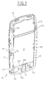
- a rear shell 10 comprises a bottom 17, corresponding to the back of the phone, bordered by a partition 12.
- a light 21a is provided on the lower part of the partition 12, corresponding to the underside of the telephone, to allow passage, by example, electrical connection devices.
- a light 12b is formed on one of the lateral parts of the partition 12, corresponding to one face side of the phone, to allow the passage, for example, of buttons ordered.
- a hollow shoulder 11 is provided (also visible in FIGS. 6, 7 and 8).
- studs 15 projecting inwardly.
- These studs 15 serve attachment means cooperating with attachment means 25 formed on the front shell 20, as will be described with reference to FIG. 2.
- These structures 110 serve first of all as holding means of the plate 30, the shell 10 of which will cover the rear part. Front surfaces 111 of these projecting structures 110 protrude relative to the free edge of the partition 12 so as to bear against the plate 30 as will be described with reference to FIG. 6.
- These projecting structures 110, projecting with respect to the free edge of the partition 12, also serve as stumbling blocks to center the two shells 10 and 20 relative to each other.
- tabs 211 serve as guide means for a means of locking 200 as well as hooking means cooperating with means 221 corresponding provided on the front shell 20 and a means of fixing 205 of the means locking 200.
- a cavity 16 is formed through the bottom 17 to allow the passage of a control member 202 of the locking means 200, as will be described with reference to Figs. 7 and 8.
- protruding legs 216 On either side of this cavity 16, are formed protruding legs 216 forming guide means cooperating with guide means 206 formed on the locking means 200, as will be described with reference to Figs. 7 and 8.
- bosses 212 On either side of the projections 216, are provided bosses 212 which will serve as locking means in cooperation with blades elastic bands 203 formed on the locking means 200, as will be described in reference to Figs. 7 and 8.
- a front shell 20 includes a bottom 27, corresponding to the front of the phone, bordered by a partition 22.
- lights 22a and 22b are respectively provided on the partition 22 in areas corresponding to the extension of areas in which lights 12a and 12b are provided on the partition 12 of the shell 10.
- lights are formed on the bottom 27 in areas corresponding to different components of the telephone, as is well known.
- housings 25 serve as attachment means with which come into takes the studs 15 formed on the rear shell 10.
- protruding structures 121 and 28 On the lateral parts of the partition 12, corresponding to the side faces of the telephone, are provided protruding structures 121 and 28.
- a pair of protruding structures 121 arranged one opposite each other on one and the other lateral part of the partition 22, acting at proximity of the free edge of the partition 22 and projecting relative to the latter, serve means for holding the plate, the shell 20 of which will cover the front part. of the parts of these projecting structures 121 are adapted to bear against the plate 30 thus that it will be described with reference to FIG. 6.
- projecting structures protruding by compared to the free edge of the partition 22, also serve as means of stumbling block allowing to center the two shells 10 and 20 relative to each other.
- Each flange 223 is reinforced by a flange 23 extending generally parallel to the lower part of the partition 12 which it extends and protruding from the free edge of the partition 12 to the level of the flanges 223.
- a flange 23 extending generally parallel to the lower part of the partition 12 which it extends and protruding from the free edge of the partition 12 to the level of the flanges 223.
- These legs 221 are smaller in size than the legs 211 and they extend at a level corresponding to the rear end of the legs 211. As will be described with reference to Figs. 7 and 8, these legs 221 serve as means hooking cooperating with the legs 211 and a fastening means 205 of the means of lock 200.
- a plate 30 comprises a plate 31 comprising the telephone printed circuit board (PCB) and its electronics (not shown) protected by a shield forming a cover attached to the plate.
- PCB printed circuit board
- the compartment 33 located at the front of the plate 31, there are components such as the keyboard, screen and the like.
- compartment 32 located at the rear of the plate 31, there are in particular components power supply and in particular the phone battery.
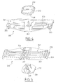
- a sliding lock 200 includes a plate elongated 201 whose center is used in particular to accommodate a control member 202 of the latch 200 and the lateral wings of which carry a member at their ends guide 204 extended by a locking member 205.
- Each of the guide members 204 is constituted by a separation of the wing corresponding side in two branches forming a U defining a groove extending in a direction perpendicular to the long length of the plate 201, corresponding to a direction of translation of the lock 200 relative to the telephone.
- the two branches of the U part At one end of this guide member 204, corresponding to a lower end when the sliding latch 200 is part of the assembly of case, the two branches of the U part at a right angle shoulder to form a larger groove constituting the locking member 205.
- the center of the plate 201 includes a hole adapted to receive the foot 208 of a control member 202. On either side of this hole, the tabs of fixing by clipping 207 allow the fixing of the control member 202 on the plate 201. On either side of these legs 207 are formed projecting guides 206 extending in the direction of translation of the latch 200.
- the control member 202 consists of a plate 209 adapted to slide against the back of the phone and a leg 208 whose free end is fixed between the fixing lugs 207. This control member projects towards the rear of the lock 200.
- the plate 30 is introduced in the front shell 20.
- the spacing of the projections 121 being less than the width of the plate 31, the plate must be forced into the shell 20, which causes a deformation of the side partitions 22 due to the force exerted by the plate 31 on the rounded part of the projections 121.
- the partitions 22 fold down, ensuring maintenance of the plate 30.
- the rear shell 10 is then placed on the front shell 20, the studs 15 being inserted in the housings 25 and the protruding shoulder 21 coming into the hollow shoulder 11.
- the surfaces upper 111 of the projections 110 come to bear against the plate 31, which contributes to maintain the plate 30 inside the housing.
- the latch 200 is installed on the rear shell 10, the plate 201 lying against the bottom 17 and occupying the entire width of the part bottom of the housing 1, the foot 208 of the control member 202 passing through the orifice 16, and the plate 209 located against the outer surface of the housing 1.
- the guide members 204 are engaged with the corresponding lugs 211, so that the latch 200 slides in the height direction of the housing 1.
- the projections 216 of the shell 10 extend against the projections 206 of the latch 200, which provides a second type of sliding guides.
- Latch 200 can slide between a position opening and closing position. In the closed position, shown in Fig.
- the fixing member 205 overlaps the lugs 211 and 221 which, when the front hulls 20 and rear 10 are assembled, are located one against the other.
- the tabs 211 and 221 being held against one another by the fixing member 205 of the lock 200, the two shells are locked and cannot move one compared to each other.
- the legs 221 being shorter than the legs 211, if the latch 200, controlled by the control member 202 which a user manipulates by means of the plate 209, is moved to the top of the housing 1, the fixing member 205 is no longer engaged with the tab 221.
- the latch 200 is then in the open position. On the other hand, whatever the position of the latch 200, whose travel is limited by the height of the orifice 16, the guide member 204 remains in engagement with the tab 211.
- the bosses 212 are arranged on the path of the latch 200.
- the elastic blades 203 of the latch 200 are located above the bosses 212.
- the elastic blades 203 are located below the bosses 212. Therefore, between these two positions, the elastic blades 203, part of which located opposite bosses 212, must be deformed in order to allow passage of latch 200. It is therefore necessary to pass from the open position to the position of closing and vice versa exert a certain force on the control member 202, which ensures system security.
Landscapes
- Engineering & Computer Science (AREA)
- Signal Processing (AREA)
- Telephone Set Structure (AREA)
Abstract
Description
Claims (13)
- Boítier de téléphone mobile à habillage amovible comprenant une platine intérieure (30) comportant des composants du téléphone mobile et deux coques (10, 20) adaptées à recevoir entre elles ladite platine intérieure (30), des moyens d'assemblage permettant d'assembler de manière démontable lesdites deux coques (10 et 20), caractérisé en ce que lesdits moyens d'assemblage comprennent un moyen de verrouillage (200) qui est monté mobile en translation sur l'une desdites coques (10) entre une position d'ouverture et une position de fermeture et qui est pourvu d'un moyen de fixation (205) adapté, lorsque ledit moyen de verrouillage (200) est dans sa position de fermeture, à rendre solidaires deux moyens d'accrochage (211, 221) respectivement prévus sur l'une et l'autre desdites coques (10 et 20).
- Boítier selon la revendication 1, caractérisé en ce que lesdits moyens d'accrochage sont deux pattes (211, 221) adaptées à s'étendre l'une contre l'autre lorsque lesdites coques (10, 20) sont installées l'une contre l'autre, ledit moyen de fixation (205) ayant un profil en U adapté à venir chevaucher lesdites pattes et à les serrer l'une contre l'autre lorsque ledit moyen de verrouillage (200) est dans sa position de fermeture.
- Boítier selon la revendication 1 ou 2, caractérisé en ce que des moyens de guidage (211, 216) ménagés sur au moins l'une des coques (10) permettent un guidage en translation dudit moyen de verrouillage (200) entre sa position d'ouverture et sa position de fermeture.
- Boítier selon la revendication 3, caractérisé en ce qu'un moyen de guidage est constitué par une desdites pattes (211) formant moyen d'accrochage, un moyen de guidage coopérant (204) étant ménagé sur ledit moyen de verrouillage (200) dans le prolongement dudit moyen de fixation (205) et ayant un profil en U adapté à chevaucher ladite patte.
- Boítier selon l'une quelconque des revendications précédentes, caractérisé en ce qu'un moyen de blocage (212) intervient sur le trajet dudit moyen de verrouillage (200) entre ladite position d'ouverture et ladite position de fermeture, ledit moyen de blocage coopérant avec un moyen élastiquement déformable (203) de manière à ce que ledit moyen de verrouillage ne puisse passer ledit moyen de blocage que lorsqu'une certaine force est exercée sur lui.
- Boítier selon l'une quelconque des revendications précédentes, caractérisé en ce qu'une commande (202) dudit moyen de verrouillage (200) au moyen de laquelle un utilisateur peut commander la translation dudit moyen de verrouillage est ménagée sur la face arrière dudit boítier.
- Boítier selon l'une quelconque des revendications précédentes, caractérisé en ce que ledit moyen de verrouillage (200) est ménagé au niveau de l'extrémité inférieure dudit boítier (1).
- Boítier selon l'une quelconque des revendications 3 à 7, caractérisé en ce que lesdits moyens de guidage (211, 216) sont ménagés sur une coque arrière (10) dudit boítier (1).
- Boítier selon l'une quelconque des revendications précédentes, caractérisé en ce que des moyens d'accrochage (15, 25) respectifs adaptés à venir en prise les uns avec les autres sont ménagés sur l'une et l'autre desdites coques (10, 20).
- Boítier selon la revendication 9, caractérisé en ce que lesdits moyens d'accrochage (15, 25) sont ménagés au niveau de l'extrémité supérieure dudit boítier (1).
- Boítier selon l'une quelconque des revendications précédentes, caractérisé en ce que au moins l'une desdites coques (20) est pourvue de moyens de maintien (121) permettant de maintenir ladite platine intérieure immobile à l'intérieur desdites deux coques lorsque ces dernières sont assemblées.
- Boítier selon l'une quelconque des revendications précédentes, caractérisé en ce que ladite platine intérieure (30) est préalablement introduite dans une coque avant (20) dudit boítier, une surface avant de ladite platine venant s'étendre contre l'intérieur de la face avant de ladite coque avant, la coque arrière (10) étant pourvue de moyens de maintien (111) permettant de maintenir ladite platine contre ladite coque avant lorsque les deux coques sont assemblées.
- Boítier selon l'une quelconque des revendications précédentes, caractérisé en ce que des moyens de confinement latéraux (28) sont ménagés sur l'intérieur des flancs d'au moins l'une desdites coques pour immobiliser latéralement ladite platine intérieure.
Applications Claiming Priority (2)
| Application Number | Priority Date | Filing Date | Title |
|---|---|---|---|
| FR0201001 | 2002-01-25 | ||
| FR0201001A FR2835379B1 (fr) | 2002-01-25 | 2002-01-25 | Boitier de telephone mobile a habillage amovible |
Publications (2)
| Publication Number | Publication Date |
|---|---|
| EP1331796A1 true EP1331796A1 (fr) | 2003-07-30 |
| EP1331796B1 EP1331796B1 (fr) | 2005-08-31 |
Family
ID=8871415
Family Applications (1)
| Application Number | Title | Priority Date | Filing Date |
|---|---|---|---|
| EP20030290100 Expired - Lifetime EP1331796B1 (fr) | 2002-01-25 | 2003-01-14 | Boítier de téléphone mobile à habillage amovible |
Country Status (5)
| Country | Link |
|---|---|
| EP (1) | EP1331796B1 (fr) |
| CN (1) | CN1264325C (fr) |
| DE (1) | DE60301408T2 (fr) |
| ES (1) | ES2245765T3 (fr) |
| FR (1) | FR2835379B1 (fr) |
Cited By (2)
| Publication number | Priority date | Publication date | Assignee | Title |
|---|---|---|---|---|
| FR2862174A1 (fr) * | 2003-11-12 | 2005-05-13 | Sagem | Boitier de telephone mobile |
| EP2282488A1 (fr) * | 2009-07-28 | 2011-02-09 | Gigaset Communications GmbH | Téléphone mobile doté d'un boîtier |
Families Citing this family (1)
| Publication number | Priority date | Publication date | Assignee | Title |
|---|---|---|---|---|
| CN114383642A (zh) * | 2021-12-14 | 2022-04-22 | 深圳市子元工业技术有限公司 | 一种具有报警功能的危险源采集传感器 |
Citations (4)
| Publication number | Priority date | Publication date | Assignee | Title |
|---|---|---|---|---|
| EP1028574A2 (fr) * | 1999-02-12 | 2000-08-16 | Nokia Mobile Phones Ltd. | Radiotéléphone |
| DE20113206U1 (de) * | 2001-08-09 | 2001-11-15 | Nokia Corp., Espoo | Mobiltelefon mit Abdeckeinrichtung und hierfür verwendete Gehäuseschalen |
| EP1158752A2 (fr) * | 2000-05-26 | 2001-11-28 | Nokia Mobile Phones Ltd. | Radiotéléphone |
| EP1168774A2 (fr) * | 2000-06-30 | 2002-01-02 | Nokia Mobile Phones Ltd. | Un assemblage de boitier |
-
2002
- 2002-01-25 FR FR0201001A patent/FR2835379B1/fr not_active Expired - Fee Related
-
2003
- 2003-01-14 ES ES03290100T patent/ES2245765T3/es not_active Expired - Lifetime
- 2003-01-14 DE DE2003601408 patent/DE60301408T2/de not_active Expired - Lifetime
- 2003-01-14 EP EP20030290100 patent/EP1331796B1/fr not_active Expired - Lifetime
- 2003-01-23 CN CN 03100864 patent/CN1264325C/zh not_active Expired - Fee Related
Patent Citations (4)
| Publication number | Priority date | Publication date | Assignee | Title |
|---|---|---|---|---|
| EP1028574A2 (fr) * | 1999-02-12 | 2000-08-16 | Nokia Mobile Phones Ltd. | Radiotéléphone |
| EP1158752A2 (fr) * | 2000-05-26 | 2001-11-28 | Nokia Mobile Phones Ltd. | Radiotéléphone |
| EP1168774A2 (fr) * | 2000-06-30 | 2002-01-02 | Nokia Mobile Phones Ltd. | Un assemblage de boitier |
| DE20113206U1 (de) * | 2001-08-09 | 2001-11-15 | Nokia Corp., Espoo | Mobiltelefon mit Abdeckeinrichtung und hierfür verwendete Gehäuseschalen |
Cited By (3)
| Publication number | Priority date | Publication date | Assignee | Title |
|---|---|---|---|---|
| FR2862174A1 (fr) * | 2003-11-12 | 2005-05-13 | Sagem | Boitier de telephone mobile |
| WO2005048566A3 (fr) * | 2003-11-12 | 2005-08-11 | Sagem | Boîtier de téléphone mobile |
| EP2282488A1 (fr) * | 2009-07-28 | 2011-02-09 | Gigaset Communications GmbH | Téléphone mobile doté d'un boîtier |
Also Published As
| Publication number | Publication date |
|---|---|
| ES2245765T3 (es) | 2006-01-16 |
| FR2835379A1 (fr) | 2003-08-01 |
| CN1434615A (zh) | 2003-08-06 |
| DE60301408D1 (de) | 2005-10-06 |
| DE60301408T2 (de) | 2006-03-16 |
| FR2835379B1 (fr) | 2004-03-12 |
| CN1264325C (zh) | 2006-07-12 |
| EP1331796B1 (fr) | 2005-08-31 |
Similar Documents
| Publication | Publication Date | Title |
|---|---|---|
| EP0846304B1 (fr) | Boitier de raccordement electronique, a un ordinateur individuel, equipe d'un connecteur pour une carte a puce | |
| FR2879833A1 (fr) | Dispositif de verrouillage d'un appareil electrique sur un rail de support | |
| FR2669008A1 (fr) | Structure de couvercle. | |
| EP1263104A1 (fr) | Accessoire d'angle pour goulotte | |
| FR2601841A1 (fr) | Dispositif electronique de vehicule automobile | |
| WO2021116542A1 (fr) | Kakemono digital | |
| FR2712257A1 (fr) | Poignée de manutention plate et rabattable notamment pour caissons de matériels électriques et/ou électroniques et caisson équipé d'une telle poignée. | |
| EP1893048A1 (fr) | Coffret avec structure deployable | |
| EP2456021B1 (fr) | Prise électrique comportant des montants latéraux mobiles en translation | |
| EP0785606B1 (fr) | Dispositif de fixation d'un appareil électrique | |
| EP1331796B1 (fr) | Boítier de téléphone mobile à habillage amovible | |
| EP0869242B1 (fr) | Ferrure de verrouillage pour ouvrant coulissant | |
| EP1071183A1 (fr) | Support d'appareillage électrique à rapporter sur une goulotte | |
| FR2871832A1 (fr) | Mecanisme de verrouillage et son procede d'actionnement | |
| CA2502936C (fr) | Dispositif de fixation par verrouillage d'un appareil destine a etre monte dans un rack | |
| EP0651483B1 (fr) | Dispositif de fixation rapide d'un support dans un coffret d'appareillage électrique | |
| FR2936829A1 (fr) | Dispositif de verrouillage. | |
| EP1137897B1 (fr) | Coffret de raccordement et de protection pour candelabre | |
| EP2700541B1 (fr) | Mécanisme de fixation rapide | |
| EP1094579A1 (fr) | Support pour le montage d'au moins un appareillage électrique sur une goulotte pour câbles et/ou conducteurs | |
| EP2199504B1 (fr) | Mécanisme de fermeture de porte et enveloppe pour appareils électriques comportant un tel mécanisme | |
| EP2773828A1 (fr) | Couvercle et bloc moteur pourvu dudit couvercle | |
| EP0454515A1 (fr) | Boîtier à compartiments multiples pour le logement de composants électriques ou électroniques | |
| EP1343238B1 (fr) | Boîtier pour appareillage électrique à fixation souple | |
| FR2852581A1 (fr) | Boitier comportant un volet de fermeture d'un orifice qui commande les moyens de verrouillage de l'ouverture du boitier |
Legal Events
| Date | Code | Title | Description |
|---|---|---|---|
| PUAI | Public reference made under article 153(3) epc to a published international application that has entered the european phase |
Free format text: ORIGINAL CODE: 0009012 |
|
| AK | Designated contracting states |
Designated state(s): AT BE BG CH CY CZ DE DK EE ES FI FR GB GR HU IE IT LI LU MC NL PT SE SI SK TR |
|
| AX | Request for extension of the european patent |
Extension state: AL LT LV MK RO |
|
| 17P | Request for examination filed |
Effective date: 20030913 |
|
| 17Q | First examination report despatched |
Effective date: 20040212 |
|
| AKX | Designation fees paid |
Designated state(s): DE ES FR GB IT |
|
| GRAP | Despatch of communication of intention to grant a patent |
Free format text: ORIGINAL CODE: EPIDOSNIGR1 |
|
| GRAS | Grant fee paid |
Free format text: ORIGINAL CODE: EPIDOSNIGR3 |
|
| GRAA | (expected) grant |
Free format text: ORIGINAL CODE: 0009210 |
|
| AK | Designated contracting states |
Kind code of ref document: B1 Designated state(s): DE ES FR GB IT |
|
| REG | Reference to a national code |
Ref country code: GB Ref legal event code: FG4D Free format text: NOT ENGLISH |
|
| REF | Corresponds to: |
Ref document number: 60301408 Country of ref document: DE Date of ref document: 20051006 Kind code of ref document: P |
|
| GBT | Gb: translation of ep patent filed (gb section 77(6)(a)/1977) |
Effective date: 20051003 |
|
| REG | Reference to a national code |
Ref country code: ES Ref legal event code: FG2A Ref document number: 2245765 Country of ref document: ES Kind code of ref document: T3 |
|
| PLBE | No opposition filed within time limit |
Free format text: ORIGINAL CODE: 0009261 |
|
| STAA | Information on the status of an ep patent application or granted ep patent |
Free format text: STATUS: NO OPPOSITION FILED WITHIN TIME LIMIT |
|
| 26N | No opposition filed |
Effective date: 20060601 |
|
| REG | Reference to a national code |
Ref country code: FR Ref legal event code: TP |
|
| REG | Reference to a national code |
Ref country code: FR Ref legal event code: TP |
|
| REG | Reference to a national code |
Ref country code: DE Ref legal event code: R082 Ref document number: 60301408 Country of ref document: DE Representative=s name: PATENT- UND RECHTSANWAELTE BARDEHLE PAGENBERG, DE |
|
| REG | Reference to a national code |
Ref country code: DE Ref legal event code: R081 Ref document number: 60301408 Country of ref document: DE Owner name: APPLE INC., CUPERTINO, US Free format text: FORMER OWNER: SAGEM MOBILES, PARIS, FR Effective date: 20111026 Ref country code: DE Ref legal event code: R082 Ref document number: 60301408 Country of ref document: DE Representative=s name: BARDEHLE PAGENBERG PARTNERSCHAFT MBB PATENTANW, DE Effective date: 20111026 Ref country code: DE Ref legal event code: R081 Ref document number: 60301408 Country of ref document: DE Owner name: APPLE INC., US Free format text: FORMER OWNER: SAGEM MOBILES, PARIS, FR Effective date: 20111026 Ref country code: DE Ref legal event code: R082 Ref document number: 60301408 Country of ref document: DE Representative=s name: BARDEHLE PAGENBERG PARTNERSCHAFT PATENTANWAELT, DE Effective date: 20111026 |
|
| REG | Reference to a national code |
Ref country code: FR Ref legal event code: TP Owner name: APPLE INC., US Effective date: 20111229 |
|
| REG | Reference to a national code |
Ref country code: GB Ref legal event code: 732E Free format text: REGISTERED BETWEEN 20120426 AND 20120502 |
|
| REG | Reference to a national code |
Ref country code: GB Ref legal event code: 732E Free format text: REGISTERED BETWEEN 20120503 AND 20120509 |
|
| REG | Reference to a national code |
Ref country code: FR Ref legal event code: PLFP Year of fee payment: 14 |
|
| PGFP | Annual fee paid to national office [announced via postgrant information from national office to epo] |
Ref country code: FR Payment date: 20151208 Year of fee payment: 14 |
|
| PGFP | Annual fee paid to national office [announced via postgrant information from national office to epo] |
Ref country code: DE Payment date: 20160105 Year of fee payment: 14 |
|
| PGFP | Annual fee paid to national office [announced via postgrant information from national office to epo] |
Ref country code: GB Payment date: 20160113 Year of fee payment: 14 |
|
| REG | Reference to a national code |
Ref country code: DE Ref legal event code: R119 Ref document number: 60301408 Country of ref document: DE |
|
| GBPC | Gb: european patent ceased through non-payment of renewal fee |
Effective date: 20170114 |
|
| REG | Reference to a national code |
Ref country code: FR Ref legal event code: ST Effective date: 20170929 |
|
| PG25 | Lapsed in a contracting state [announced via postgrant information from national office to epo] |
Ref country code: FR Free format text: LAPSE BECAUSE OF NON-PAYMENT OF DUE FEES Effective date: 20170131 |
|
| PG25 | Lapsed in a contracting state [announced via postgrant information from national office to epo] |
Ref country code: DE Free format text: LAPSE BECAUSE OF NON-PAYMENT OF DUE FEES Effective date: 20170801 Ref country code: GB Free format text: LAPSE BECAUSE OF NON-PAYMENT OF DUE FEES Effective date: 20170114 |
|
| PGFP | Annual fee paid to national office [announced via postgrant information from national office to epo] |
Ref country code: IT Payment date: 20211213 Year of fee payment: 20 Ref country code: ES Payment date: 20220203 Year of fee payment: 20 |
|
| REG | Reference to a national code |
Ref country code: ES Ref legal event code: FD2A Effective date: 20230426 |
|
| PG25 | Lapsed in a contracting state [announced via postgrant information from national office to epo] |
Ref country code: ES Free format text: LAPSE BECAUSE OF EXPIRATION OF PROTECTION Effective date: 20230115 |