EP1331712A1 - Appareil électrique à fixer sur un profilé chapeau - Google Patents
Appareil électrique à fixer sur un profilé chapeau Download PDFInfo
- Publication number
- EP1331712A1 EP1331712A1 EP03075468A EP03075468A EP1331712A1 EP 1331712 A1 EP1331712 A1 EP 1331712A1 EP 03075468 A EP03075468 A EP 03075468A EP 03075468 A EP03075468 A EP 03075468A EP 1331712 A1 EP1331712 A1 EP 1331712A1
- Authority
- EP
- European Patent Office
- Prior art keywords
- slide
- base
- lever
- electrical device
- axis
- Prior art date
- Legal status (The legal status is an assumption and is not a legal conclusion. Google has not performed a legal analysis and makes no representation as to the accuracy of the status listed.)
- Granted
Links
- 238000005192 partition Methods 0.000 claims description 5
- 238000000465 moulding Methods 0.000 claims description 2
- 210000005069 ears Anatomy 0.000 description 2
- 230000000295 complement effect Effects 0.000 description 1
- 230000005489 elastic deformation Effects 0.000 description 1
- 210000000056 organ Anatomy 0.000 description 1
Images



Classifications
-
- H—ELECTRICITY
- H02—GENERATION; CONVERSION OR DISTRIBUTION OF ELECTRIC POWER
- H02B—BOARDS, SUBSTATIONS OR SWITCHING ARRANGEMENTS FOR THE SUPPLY OR DISTRIBUTION OF ELECTRIC POWER
- H02B1/00—Frameworks, boards, panels, desks, casings; Details of substations or switching arrangements
- H02B1/015—Boards, panels, desks; Parts thereof or accessories therefor
- H02B1/04—Mounting thereon of switches or of other devices in general, the switch or device having, or being without, casing
- H02B1/052—Mounting on rails
-
- H—ELECTRICITY
- H05—ELECTRIC TECHNIQUES NOT OTHERWISE PROVIDED FOR
- H05K—PRINTED CIRCUITS; CASINGS OR CONSTRUCTIONAL DETAILS OF ELECTRIC APPARATUS; MANUFACTURE OF ASSEMBLAGES OF ELECTRICAL COMPONENTS
- H05K7/00—Constructional details common to different types of electric apparatus
- H05K7/14—Mounting supporting structure in casing or on frame or rack
- H05K7/1462—Mounting supporting structure in casing or on frame or rack for programmable logic controllers [PLC] for automation or industrial process control
- H05K7/1474—Mounting of modules, e.g. on a base or rail or wall
-
- H—ELECTRICITY
- H02—GENERATION; CONVERSION OR DISTRIBUTION OF ELECTRIC POWER
- H02B—BOARDS, SUBSTATIONS OR SWITCHING ARRANGEMENTS FOR THE SUPPLY OR DISTRIBUTION OF ELECTRIC POWER
- H02B1/00—Frameworks, boards, panels, desks, casings; Details of substations or switching arrangements
- H02B1/015—Boards, panels, desks; Parts thereof or accessories therefor
- H02B1/04—Mounting thereon of switches or of other devices in general, the switch or device having, or being without, casing
- H02B1/052—Mounting on rails
- H02B1/0523—Mounting on rails locked into position by a sliding member
-
- H—ELECTRICITY
- H02—GENERATION; CONVERSION OR DISTRIBUTION OF ELECTRIC POWER
- H02B—BOARDS, SUBSTATIONS OR SWITCHING ARRANGEMENTS FOR THE SUPPLY OR DISTRIBUTION OF ELECTRIC POWER
- H02B1/00—Frameworks, boards, panels, desks, casings; Details of substations or switching arrangements
- H02B1/015—Boards, panels, desks; Parts thereof or accessories therefor
- H02B1/04—Mounting thereon of switches or of other devices in general, the switch or device having, or being without, casing
- H02B1/052—Mounting on rails
- H02B1/0526—Mounting on rails locking or releasing devices actuated from the front face of the apparatus
Definitions
- the present invention relates to an electrical appliance comprising a base to be fixed on a support profile, in particular a hat profile, with opposite coplanar branches, the base being provided with a locking device with two opposite fixing notches intended to hang each on a respective branch of the profile, at least one of notches being integral with a slide which is capable of sliding in a determined direction, transverse to the length of the profile, and which can be moved by a manual member unlocking.
- Document FR 2 730 353 shows a device for locking an electrical appliance on a supporting profile rail, the device having two notches connected together by a spacer spacer whose elastic deformation can be caused by a pull tab accessible from the front. The device is released from the rail at by means of a side pull which is not easy to handle.
- a device is not suitable for the secure reception of another component part of a device electrical with base, in particular a processing module, a terminal block, etc ... removable on the base.
- the invention aims to fix a base on a support profile while allowing unlock the base by means on the one hand easy to maneuver, on the other hand clean to secure the contribution of another component member of the device on the base.
- the manual unlocking member comprises a pivotally mounted lever around at least one pin journal perpendicular to the sliding direction of the slide, the pin being in particular located near the bottom of the base, and the lever cooperates with the slide by a cam device provided with a slide guiding a parallel axis to the axis of the journal.
- the lever is preferably lockable in its unlocking positions and locking.
- the lever can have a maneuvering arm erased in a locking position and projecting forward in an unlocking position, to cooperate with a rear face of the module in order to prohibit the mounting of the module on the base. in the unlocked position and allow this mounting in the locked position. It is advantageous for the two notches to be displaceable, by securing with symmetrical slides relative to a median plane of the base, the lever cooperating with the slides by two cams and symmetrical axes.
- the cam slide is integrated into the lever and the slide has the axis guided in the slide, this axis being guided in a slot or groove in the base which extends in the sliding direction of the slide.
- the slide can advantageously come from molding with the bottom, being separated from rigid partitions of the bottom by slots.
- the bottom may have two housings intended to receive the branches of the profile cap and the part of the lever fitted with cam slides is projecting backwards between these housings.
- Figure 1 shows in exploded perspective a modular device according to the invention.
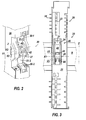
- Figure 2 shows in rear perspective the central part of the base of the Figure 1.
- Figure 3 is a front view of the base, the lever being in its locked position.
- Figure 4 is a side view of the base, the lever being in its locked position (in solid lines) and in its unlocked position (in dashes).
- Figures 5 and 6 show in perspective front and e side view of the unlocked lever.
- Figure 7 is an exploded perspective view of the lever and one of the associated slides.
- the apparatus illustrated in the figures comprises several electronic modules 10 intended to be nested and snapped into individual bases 20 themselves snap-in adjacent by any usual means on a bearing cap profile.
- several modules 10 can be nested in adjacent housings in a single base.
- the hat profile R has a profile standardized to two opposite branches R1, R2 and extends in a direction X. In the operating state of the device, the module is fixed on the base.
- Each module 10 comprises a housing 11 having a front face 11a and a face rear 11b.
- a terminal block 12 for external connection to electrical automation components to be controlled or monitored, connections 14 being provided towards the front face 11a to cooperate with connections or contacts complementary to terminal block 12.
- Connection elements or rear contacts 13 are arranged towards the rear face 11b of the housing.
- the base 20 determines a housing for the rear part of the module 10. It comprises a bottom 21, side walls in the form of vertical partitions 25, 26, an upper wall 27 and a bottom wall 28 horizontal.
- the bottom 21 is provided with a device for elastic locking 30 on the profile R.
- the bottom 21 has front connections 23 able to cooperate with the contacts 13 of module 10 when the base is locked on profile R.
- the base also has side contacts 24 which are used to transmit bus signals to or from source of the modules and the supply potentials which are intended for the modules or to the automation organs.
- the walls 25-28 include faces, slides or other guide elements facilitating the introduction of the module.
- recesses 29 are provided which cooperate with pawls, elastic parts or other forms of attachment 15 of the module.
- the forms 15 are maneuverable for example by two upper and lower pushers 16, in order to lock the module 10 in its position pressed into the base 20, position in which it is fitted between the walls 25-28.
- the locking device 30 comprises two opposite fixing notches 30 (30-1,30-2) each linked to a slide 31 (31-1,31-2) movable in a vertical direction Z, which corresponds to the length of the base 20 and which is perpendicular to X.
- each slide is attached to a rigid part 32 of the bottom 21 of the base in the manner of an articulated connection, this connection nevertheless authorizing the sliding of the slide.
- the slide 31 is constituted by a very part of the bottom 21, separated from rigid partitions 33 of the bottom by slots 34 directed according to Z.
- the locking device 30 comprises an unlocking member constituted by a lever 40 pivoting about a journaling axis X1 parallel to the direction X.
- the lever 40 has for this purpose lateral pins 41 which pivot in orifices of the bottom 21.
- the lever has a manual control arm 42 and a pivot body provided two cam slides 43 in each of which an axis 44 can move directed in a direction X2, X3 parallel to X and engaged on the one hand in a cylindrical hole 35 of the respective slide 31 and on the other hand in oblong slots or grooves 36, directed along Z, and provided in ears 37 at the bottom.
- Ears 37 and body slides 43 are arranged projecting rearwards in an intermediate space between the housing zones 38 of the branches of the profile R1, R2, this projection being housed in the central removal of the profile.
- the lever thus occupies a very small space at the bottom of the base.
- a pin return spring 39 is associated with one of the sliders 31-2 for arbouter against him and push him back to plane P.
- the rear wall 11b of the electronic module abuts against the arm 42 for operating the lever 40 when the latter occupies its substantially horizontal position release (indicated in dashes).
- the wall 11b authorizes the fixing of the module on the base and the connection of the contacts 13 and 21 when the arm 42 is brought into its substantially vertical locking position (in solid lines). Of even, when the module is fixed and connected, it prohibits unlocking the base 20 of the profile R.
- the lever 40 being in its unlocking position ( Figures 5 and 6, or in dashed lines in Figure 4) by being held in this position by hard points or threshold latching effort, the sliders are then moved apart (see position in dashes in figure 4) and the base can thus be applied to the branches of the profile R; the operator then rotates the lever to its locking position (see position in solid lines in Figure 4) and the sliders come to hang on the edges of the branches, the movement being helped by the spring 38.
- the lever remains held in this position by a hard or snap point.
- the module can then be engaged in the base and be connected and fixed to it. so that the lever 40 is in the unlocked position, it is not possible to slide and connect the electronic module 10 to the base 20 (see this position illustrated in dashes in Figure 4).
Landscapes
- Engineering & Computer Science (AREA)
- Automation & Control Theory (AREA)
- Microelectronics & Electronic Packaging (AREA)
- Power Engineering (AREA)
- Casings For Electric Apparatus (AREA)
- Mounting Of Printed Circuit Boards And The Like (AREA)
- Mounting Components In General For Electric Apparatus (AREA)
Abstract
Description
Il est avantageux que les deux crans soient déplaçables, par solidarisation avec des coulisseaux symétriques relativement à un plan médian de l'embase, le levier coopérant avec les coulisseaux par deux cames et axes symétriques.
Claims (10)
- Appareil électrique comprenant une embase à fixer sur un profilé porteur, notamment un profilé chapeau, à branches coplanaires opposées, l'embase pouvant recevoir un organe constituant de l'appareil et étant dotée d'un dispositif de verrouillage à deux crans opposés de fixation (30) destinés à s'accrocher chacun sur une branche respective du profilé, l'un au moins des crans étant solidaire d'un coulisseau (31) qui est apte à glisser selon une direction (Z) et est déplaçable par un organe manuel de déverrouillage,
caractérisé par le fait quel'organe manuel de déverrouillage comprend un levier (40) monté pivotant autour d'au moins un tourillon (41) d'axe (X1) perpendiculaire à la direction (Z) de glissement du coulisseau,le levier (40) coopère avec le coulisseau (31) par un dispositif de came à glissière guidant un axe (44) parallèle à l'axe (X1) du tourillon. - Appareil électrique selon la revendication 1, caractérisé par le fait que le tourillon (41) du levier pivotant (40) est situé près du fond (21) de l'embase.
- Appareil électrique selon la revendication 1, caractérisé par le fait que les deux crans (31-1,30-2) sont déplaçables, en étant solidaires de coulisseaux (31-1,31-2) symétriques par rapport à un plan médian (P) de l'embase, le levier (40) coopérant avec les coulisseaux par deux cames et axes symétriques (43,44).
- Appareil électrique selon la revendication 1, caractérisé par le fait qu'au levier (40) est intégrée la glissière de came (43) et le coulisseau (31) présente l'axe (44) guidé dans la glissière.
- Appareil électrique selon la revendication 4, caractérisé par le fait que l'axe (44) du coulisseau (31) est guidé dans une fente ou rainure (36) de l'embase (20), qui s'étend selon la direction (Z) de glissement du coulisseau.
- Appareil électrique selon la revendication 1, caractérisé par le fait que l'embase (20) comporte une paroi de fond rigide et le coulisseau vient de moulage avec le fond, en étant séparé de cloisons rigides (33) du fond par des fentes (34).
- Appareil électrique selon la revendication 2, caractérisé par le fait qu'un ressort de rappel (39) en épingle est associé à l'un des coulisseaux (31-2).
- Appareil électrique selon la revendication 2, caractérisé par le fait que le fond (21) présente deux logements (38) destinés à recevoir les branches du profilé chapeau et la partie du levier dotée des glissières de came (43) est disposée en saillie vers l'arrière entre ces logements.
- Appareil électrique selon la revendication 1, caractérisé par le fait que le levier (40) est arrêté dans sa position de déverrouillage et dans sa position de verrouillage par des moyens de retenue à seuil d'effort.
- Appareil électrique selon la revendication 1, caractérisé par le fait que l'appareil comprend un module électronique (10) fixé de manière amovible à l'embase (20), le levier pivotant (40) présentant un bras de manoeuvre effacé dans une position de verrouillage et en saillie vers l'avant dans une position de déverrouillage, afin de coopérer avec une face arrière du module pour interdire son montage sur l'embase dans la position de déverrouillage et le permettre dans la position de verrouillage.
Applications Claiming Priority (2)
| Application Number | Priority Date | Filing Date | Title |
|---|---|---|---|
| FR0201002A FR2835358B1 (fr) | 2002-01-25 | 2002-01-25 | Appareil electrique a fixer sur un profile chapeau |
| FR0201002 | 2002-01-25 |
Publications (2)
| Publication Number | Publication Date |
|---|---|
| EP1331712A1 true EP1331712A1 (fr) | 2003-07-30 |
| EP1331712B1 EP1331712B1 (fr) | 2012-04-18 |
Family
ID=8871416
Family Applications (1)
| Application Number | Title | Priority Date | Filing Date |
|---|---|---|---|
| EP03075468A Expired - Lifetime EP1331712B1 (fr) | 2002-01-25 | 2003-01-23 | Appareil électrique à fixer sur un profilé chapeau |
Country Status (3)
| Country | Link |
|---|---|
| US (1) | US6840819B2 (fr) |
| EP (1) | EP1331712B1 (fr) |
| FR (1) | FR2835358B1 (fr) |
Cited By (2)
| Publication number | Priority date | Publication date | Assignee | Title |
|---|---|---|---|---|
| US20140339186A1 (en) * | 2013-05-16 | 2014-11-20 | Control Techniques Limited | Device For Locking To A DIN Rail |
| WO2019211346A1 (fr) * | 2018-05-03 | 2019-11-07 | Latelec | Procédé de verrouillage / déverrouillage d'un module amovible et ensemble de mise en oeuvre |
Families Citing this family (33)
| Publication number | Priority date | Publication date | Assignee | Title |
|---|---|---|---|---|
| DE102004057705A1 (de) | 2004-11-30 | 2006-06-08 | Block Transformatoren-Elektronik Gmbh & Co Kg Verden | Klemmvorrichtung zur lösbaren Befestigung eines Gerätegehäuses an einer Profilschiene |
| FR2879833B1 (fr) * | 2004-12-16 | 2008-06-13 | Schneider Electric Ind Sas | Dispositif de verrouillage d'un appareil electrique sur un rail de support |
| WO2006069634A1 (fr) * | 2004-12-24 | 2006-07-06 | Abb Patent Gmbh | Dispositif de fixation rapide sur un appareil d'installation electrique |
| DE202006006615U1 (de) * | 2006-04-22 | 2006-09-07 | Phoenix Contact Gmbh & Co. Kg | Elektronikgehäuse |
| FR2907270B1 (fr) * | 2006-10-13 | 2008-12-19 | Abb Entrelec Soc Par Actions S | Appareil electrique,destine a etre fixe sur un rail support, et procede de montage correspondant |
| DE202007005373U1 (de) * | 2007-04-12 | 2008-08-21 | Weidmüller Interface GmbH & Co. KG | Reihenklemmensystem |
| ATE533214T1 (de) * | 2007-06-14 | 2011-11-15 | Bticino Spa | Modulares elektrisches gerät mit vorrichtung zum festklammern an eine schiene |
| DE102009037203A1 (de) * | 2009-01-15 | 2010-07-29 | Bartec Gmbh | Gerät |
| JP5229956B2 (ja) * | 2009-02-03 | 2013-07-03 | 株式会社ヨコオ | 中継コネクタの固定構造 |
| US8986033B2 (en) * | 2010-03-31 | 2015-03-24 | Weidmueller Interface Gmbh & Co. Kg | Connection module being capable of serving as a bus |
| DE102011110182A1 (de) | 2011-08-09 | 2013-02-14 | Pilz Gmbh & Co. Kg | Modulare Steuerungsvorrichtung |
| JP5914094B2 (ja) * | 2012-03-29 | 2016-05-11 | 株式会社サンコーシヤ | 保安器のdinレールへの取付装置 |
| US9136648B2 (en) * | 2012-07-12 | 2015-09-15 | Rockwell Automation Technologies, Inc. | Din or panel ground integral to connector body |
| DE102013103544A1 (de) * | 2013-04-09 | 2014-10-09 | Block Transformatoren-Elektronik Gmbh | Klemmvorrichtung zur lösbaren Befestigung eines Gerätegehäuses an einer Profilschiene |
| WO2015048428A1 (fr) * | 2013-09-26 | 2015-04-02 | Abb Technology Ag | Système de commande monté sur rail |
| DE102013111580B4 (de) | 2013-10-21 | 2018-04-26 | Wago Verwaltungsgesellschaft Mbh | Elektronikgerät |
| DE102013111551B3 (de) * | 2013-10-21 | 2015-01-22 | Wago Verwaltungsgesellschaft Mbh | Tragschienengehäuse |
| GB2521445A (en) * | 2013-12-20 | 2015-06-24 | Control Tech Ltd | Mounting Latch |
| CN204046995U (zh) * | 2014-09-09 | 2014-12-24 | 泰科电子(上海)有限公司 | 固定支架和控制设备 |
| US9374924B2 (en) * | 2014-09-16 | 2016-06-21 | Schneider Electric Buildings, Llc | DIN rail mounted enclosure assembly and method of use |
| CN208707083U (zh) * | 2015-03-02 | 2019-04-05 | Abb瑞士股份有限公司 | 用于控制系统的模块组件 |
| DE212016000058U1 (de) * | 2015-03-02 | 2018-04-15 | Abb Schweiz Ag | An einer Schiene anbringbares Steuersystem mit verbesserter Kühlung |
| CN106469876B (zh) * | 2015-08-17 | 2018-11-23 | 町洋企业股份有限公司 | 连接器模块 |
| US9583849B1 (en) * | 2015-09-16 | 2017-02-28 | Dinkle Enterprise Co., Ltd. | Connector module with multiple connection modes |
| ES2719810T3 (es) * | 2015-11-04 | 2019-07-16 | Selectron Systems Ag | Módulo de sujeción por apriete para la fijación en un raíl de soporte |
| DE102016102612A1 (de) | 2016-02-15 | 2017-08-17 | Phoenix Contact Gmbh & Co. Kg | Trägeranordnung zum Tragen eines Elektronikgehäuses |
| DE202017104590U1 (de) * | 2017-08-01 | 2018-11-06 | Wago Verwaltungsgesellschaft Mbh | Elektrisches Reiheneinbaugerät und Reiheneinbaugeräte-Anordnung |
| JP2019079887A (ja) * | 2017-10-23 | 2019-05-23 | オムロン株式会社 | 電気器具のdinレール取付部構造及びソケット |
| USD1087970S1 (en) * | 2022-11-07 | 2025-08-12 | Siemens Aktiengesellschaft | Data processing device |
| US12621947B2 (en) | 2023-05-30 | 2026-05-05 | Moxa Inc. | Backplane assembly kit, related detachable assembly kit and related electronic device |
| US12526946B2 (en) * | 2023-05-30 | 2026-01-13 | Moxa Inc. | Rail mounting backplane assembly kit and related rail mounting electronic device |
| EP4472367A1 (fr) * | 2023-05-30 | 2024-12-04 | Moxa Inc. | Kit d'assemblage de fond de panier, kit d'assemblage détachable associé et dispositif électronique associé |
| DE202024105437U1 (de) * | 2024-09-20 | 2026-01-05 | WAGO Verwaltungsgesellschaft mit beschränkter Haftung | Adapter zum Befestigen einer Vorrichtung auf einer Tragschiene |
Citations (1)
| Publication number | Priority date | Publication date | Assignee | Title |
|---|---|---|---|---|
| EP0740499A1 (fr) * | 1995-04-21 | 1996-10-30 | MAN Roland Druckmaschinen AG | Fixation d'un appareillage sur un rail |
Family Cites Families (7)
| Publication number | Priority date | Publication date | Assignee | Title |
|---|---|---|---|---|
| US5090922A (en) * | 1990-12-20 | 1992-02-25 | Square D Company | Terminal block with multiple track mounting capability |
| US5145418A (en) * | 1991-06-07 | 1992-09-08 | Allen-Bradley Company, Inc. | Terminal block segment with feet for mounting on tracks of two different widths |
| US5192227A (en) * | 1991-12-23 | 1993-03-09 | Square D Company | Din rail mounting bracket |
| CH683047A5 (de) * | 1992-02-18 | 1993-12-31 | Woertz Ag | Schutzleiterklemme. |
| US5602363A (en) * | 1993-09-07 | 1997-02-11 | Watlow/Winona, Inc. | Din rail mounted enclosure |
| FR2746219B1 (fr) * | 1996-03-18 | 1998-05-07 | Auxiliaire de connexion et/ou deconnexion de liaison(s) pour module de raccordement et alignement de modules de raccordement identiques ou similaires d'un ensemble et ensemble modulaire de raccordement correspondant | |
| US6146213A (en) * | 1998-12-10 | 2000-11-14 | Yoon; Heung-Sik | Wire connection with exchangeable securing member for electric connection terminal assembly |
-
2002
- 2002-01-25 FR FR0201002A patent/FR2835358B1/fr not_active Expired - Lifetime
-
2003
- 2003-01-23 EP EP03075468A patent/EP1331712B1/fr not_active Expired - Lifetime
- 2003-01-24 US US10/349,963 patent/US6840819B2/en not_active Expired - Lifetime
Patent Citations (1)
| Publication number | Priority date | Publication date | Assignee | Title |
|---|---|---|---|---|
| EP0740499A1 (fr) * | 1995-04-21 | 1996-10-30 | MAN Roland Druckmaschinen AG | Fixation d'un appareillage sur un rail |
Cited By (5)
| Publication number | Priority date | Publication date | Assignee | Title |
|---|---|---|---|---|
| US20140339186A1 (en) * | 2013-05-16 | 2014-11-20 | Control Techniques Limited | Device For Locking To A DIN Rail |
| US9312667B2 (en) * | 2013-05-16 | 2016-04-12 | Control Techniques Limited | Device for locking to a DIN rail |
| WO2019211346A1 (fr) * | 2018-05-03 | 2019-11-07 | Latelec | Procédé de verrouillage / déverrouillage d'un module amovible et ensemble de mise en oeuvre |
| FR3080973A1 (fr) * | 2018-05-03 | 2019-11-08 | Latelec | Procede de verrouillage / deverrouillage d'un module amovible et ensemble de mise en oeuvre |
| US11751352B2 (en) | 2018-05-03 | 2023-09-05 | Latelec | Method for locking/unlocking a removable module, and assembly for implementation |
Also Published As
| Publication number | Publication date |
|---|---|
| EP1331712B1 (fr) | 2012-04-18 |
| US20030143896A1 (en) | 2003-07-31 |
| FR2835358B1 (fr) | 2004-09-10 |
| FR2835358A1 (fr) | 2003-08-01 |
| US6840819B2 (en) | 2005-01-11 |
Similar Documents
| Publication | Publication Date | Title |
|---|---|---|
| EP1331712B1 (fr) | Appareil électrique à fixer sur un profilé chapeau | |
| EP1672743B1 (fr) | Dispositif de verrouillage d'un appareil électrique sur un rail de support | |
| EP0612090B1 (fr) | Dispositif de commande rotative d'un disjoncteur | |
| EP0186556B1 (fr) | Système et colonne de distribution pour appareils électriques interrupteurs | |
| EP0681421A2 (fr) | Dispositif d'automatisation modulaire | |
| FR3000718A1 (fr) | Dispositif de pliage pour dispositif de porte-bicyclettes | |
| EP2369701B1 (fr) | Coffret ou tableau de distribution électrique, équipé de supports de rail à liaison pivot simple | |
| EP1768477B1 (fr) | Système de maintien en position d'un assemblage à trois parties assurant un effort de compression prédéterminé sur la partie intermédiaire | |
| EP2369698A1 (fr) | Support de rail de montage d'appareillages électriques dans un coffret électrique | |
| CA2502936C (fr) | Dispositif de fixation par verrouillage d'un appareil destine a etre monte dans un rack | |
| EP0233420B1 (fr) | Dispositif de prise de courant sectionnable sur une colonne de distribution à barres omnibus | |
| EP3529867B1 (fr) | Appareil electrique comprenant un dispositif de verrouillage pour rail de fixation | |
| EP2369699A1 (fr) | Coffret ou tableau de distribution électrique comportant un rail de montage d'appareillages électriques amovible | |
| EP0620625B1 (fr) | Châssis de débrochage pour un disjoncteur | |
| EP2182541A2 (fr) | Connecteur électrique comportant un levier pour son verrouillage sur un appareil modulaire | |
| CA2245245C (fr) | Dispositif de commande ou de signalisation tel qu'un bouton-poussoir | |
| EP2320532B1 (fr) | Dispositif de montage d'un montant de châssis sur le fond d'un coffret électrique et coffret électrique comprenant un tel dispositif | |
| EP1439621B1 (fr) | Appareillage du type modulaire à monter sur des barres de différentes épaisseurs | |
| EP4256662B1 (fr) | Dispositif de châssis pour appareil électrique de coupure débrochable et ensemble comprenant un tel dispositif et un tel appareil | |
| EP4043290B1 (fr) | Dispositif de maintien d'un appareil électronique portable dans un véhicule automobile | |
| FR2604033A1 (fr) | Mecanisme de connexion pour connecter un connecteur de cable a une douille | |
| EP0834794A1 (fr) | Armoire de distribution électrique munie d'un casier logeant une tablette extractible | |
| FR2736472A1 (fr) | Bloc de jonction electrique a fixer sur un profile de support | |
| CH716357B1 (fr) | Appareil modulaire électrique muni d'un élément de blocage. | |
| FR2701592A1 (fr) | Dispositif de commande rotative d'un disjoncteur. |
Legal Events
| Date | Code | Title | Description |
|---|---|---|---|
| PUAI | Public reference made under article 153(3) epc to a published international application that has entered the european phase |
Free format text: ORIGINAL CODE: 0009012 |
|
| AK | Designated contracting states |
Designated state(s): AT BE BG CH CY CZ DE DK EE ES FI FR GB GR HU IE IT LI LU MC NL PT SE SI SK TR |
|
| AX | Request for extension of the european patent |
Extension state: AL LT LV MK RO |
|
| RIN1 | Information on inventor provided before grant (corrected) |
Inventor name: RIX, PHILIPPE Inventor name: DELVAUX, FREDERIC Inventor name: BET, ROBERT Inventor name: GIRARD, MICHEL |
|
| 17P | Request for examination filed |
Effective date: 20031002 |
|
| AKX | Designation fees paid |
Designated state(s): DE GB IT |
|
| 17Q | First examination report despatched |
Effective date: 20111017 |
|
| GRAP | Despatch of communication of intention to grant a patent |
Free format text: ORIGINAL CODE: EPIDOSNIGR1 |
|
| GRAS | Grant fee paid |
Free format text: ORIGINAL CODE: EPIDOSNIGR3 |
|
| GRAA | (expected) grant |
Free format text: ORIGINAL CODE: 0009210 |
|
| AK | Designated contracting states |
Kind code of ref document: B1 Designated state(s): DE GB IT |
|
| REG | Reference to a national code |
Ref country code: GB Ref legal event code: FG4D Free format text: NOT ENGLISH |
|
| REG | Reference to a national code |
Ref country code: DE Ref legal event code: R096 Ref document number: 60340631 Country of ref document: DE Effective date: 20120614 |
|
| PLBE | No opposition filed within time limit |
Free format text: ORIGINAL CODE: 0009261 |
|
| STAA | Information on the status of an ep patent application or granted ep patent |
Free format text: STATUS: NO OPPOSITION FILED WITHIN TIME LIMIT |
|
| 26N | No opposition filed |
Effective date: 20130121 |
|
| REG | Reference to a national code |
Ref country code: DE Ref legal event code: R097 Ref document number: 60340631 Country of ref document: DE Effective date: 20130121 |
|
| PGFP | Annual fee paid to national office [announced via postgrant information from national office to epo] |
Ref country code: GB Payment date: 20220118 Year of fee payment: 20 Ref country code: DE Payment date: 20220127 Year of fee payment: 20 |
|
| PGFP | Annual fee paid to national office [announced via postgrant information from national office to epo] |
Ref country code: IT Payment date: 20220119 Year of fee payment: 20 |
|
| REG | Reference to a national code |
Ref country code: DE Ref legal event code: R071 Ref document number: 60340631 Country of ref document: DE |
|
| REG | Reference to a national code |
Ref country code: GB Ref legal event code: PE20 Expiry date: 20230122 |
|
| PG25 | Lapsed in a contracting state [announced via postgrant information from national office to epo] |
Ref country code: GB Free format text: LAPSE BECAUSE OF EXPIRATION OF PROTECTION Effective date: 20230122 |