EP1331677A2 - Battery and electric double layer capacitor - Google Patents
Battery and electric double layer capacitor Download PDFInfo
- Publication number
- EP1331677A2 EP1331677A2 EP03250290A EP03250290A EP1331677A2 EP 1331677 A2 EP1331677 A2 EP 1331677A2 EP 03250290 A EP03250290 A EP 03250290A EP 03250290 A EP03250290 A EP 03250290A EP 1331677 A2 EP1331677 A2 EP 1331677A2
- Authority
- EP
- European Patent Office
- Prior art keywords
- current collector
- sheet
- laminated
- resin sheet
- battery
- Prior art date
- Legal status (The legal status is an assumption and is not a legal conclusion. Google has not performed a legal analysis and makes no representation as to the accuracy of the status listed.)
- Withdrawn
Links
- 239000003990 capacitor Substances 0.000 title claims abstract description 36
- 229920005989 resin Polymers 0.000 claims abstract description 64
- 239000011347 resin Substances 0.000 claims abstract description 64
- 239000003792 electrolyte Substances 0.000 claims abstract description 34
- 229910052751 metal Inorganic materials 0.000 claims description 39
- 239000002184 metal Substances 0.000 claims description 39
- 230000001747 exhibiting effect Effects 0.000 abstract description 2
- 238000007789 sealing Methods 0.000 description 24
- OKTJSMMVPCPJKN-UHFFFAOYSA-N Carbon Chemical compound [C] OKTJSMMVPCPJKN-UHFFFAOYSA-N 0.000 description 17
- 230000000052 comparative effect Effects 0.000 description 17
- 238000004519 manufacturing process Methods 0.000 description 15
- 239000000843 powder Substances 0.000 description 11
- QAOWNCQODCNURD-UHFFFAOYSA-N Sulfuric acid Chemical compound OS(O)(=O)=O QAOWNCQODCNURD-UHFFFAOYSA-N 0.000 description 10
- 230000004927 fusion Effects 0.000 description 9
- 230000002378 acidificating effect Effects 0.000 description 8
- 239000011149 active material Substances 0.000 description 7
- 230000007797 corrosion Effects 0.000 description 7
- 238000005260 corrosion Methods 0.000 description 7
- 238000002156 mixing Methods 0.000 description 6
- 239000000126 substance Substances 0.000 description 6
- 229910052799 carbon Inorganic materials 0.000 description 5
- 229920000554 ionomer Polymers 0.000 description 5
- 239000000463 material Substances 0.000 description 5
- 239000000203 mixture Substances 0.000 description 5
- 238000003825 pressing Methods 0.000 description 5
- 239000013638 trimer Substances 0.000 description 5
- 238000004073 vulcanization Methods 0.000 description 5
- SIKJAQJRHWYJAI-UHFFFAOYSA-N Indole Chemical compound C1=CC=C2NC=CC2=C1 SIKJAQJRHWYJAI-UHFFFAOYSA-N 0.000 description 4
- 239000007787 solid Substances 0.000 description 4
- 239000000243 solution Substances 0.000 description 4
- 239000011230 binding agent Substances 0.000 description 3
- 238000000034 method Methods 0.000 description 3
- 238000000465 moulding Methods 0.000 description 3
- 238000007639 printing Methods 0.000 description 3
- 238000005549 size reduction Methods 0.000 description 3
- 239000002904 solvent Substances 0.000 description 3
- YHYLDEVWYOFIJK-UHFFFAOYSA-N 1h-indole-5-carbonitrile Chemical compound N#CC1=CC=C2NC=CC2=C1 YHYLDEVWYOFIJK-UHFFFAOYSA-N 0.000 description 2
- RYGMFSIKBFXOCR-UHFFFAOYSA-N Copper Chemical compound [Cu] RYGMFSIKBFXOCR-UHFFFAOYSA-N 0.000 description 2
- 239000004743 Polypropylene Substances 0.000 description 2
- 229910052782 aluminium Inorganic materials 0.000 description 2
- XAGFODPZIPBFFR-UHFFFAOYSA-N aluminium Chemical compound [Al] XAGFODPZIPBFFR-UHFFFAOYSA-N 0.000 description 2
- 229910052802 copper Inorganic materials 0.000 description 2
- 239000010949 copper Substances 0.000 description 2
- 238000000151 deposition Methods 0.000 description 2
- 239000007772 electrode material Substances 0.000 description 2
- 229920001038 ethylene copolymer Polymers 0.000 description 2
- 239000011888 foil Substances 0.000 description 2
- 238000005470 impregnation Methods 0.000 description 2
- PZOUSPYUWWUPPK-UHFFFAOYSA-N indole Natural products CC1=CC=CC2=C1C=CN2 PZOUSPYUWWUPPK-UHFFFAOYSA-N 0.000 description 2
- RKJUIXBNRJVNHR-UHFFFAOYSA-N indolenine Natural products C1=CC=C2CC=NC2=C1 RKJUIXBNRJVNHR-UHFFFAOYSA-N 0.000 description 2
- 125000001041 indolyl group Chemical group 0.000 description 2
- -1 polypropylene Polymers 0.000 description 2
- 229920001155 polypropylene Polymers 0.000 description 2
- 238000003756 stirring Methods 0.000 description 2
- CBTITARLOCZPDU-UHFFFAOYSA-N 1h-indole-2-carbonitrile Chemical compound C1=CC=C2NC(C#N)=CC2=C1 CBTITARLOCZPDU-UHFFFAOYSA-N 0.000 description 1
- 229920003026 Acene Polymers 0.000 description 1
- 229910000838 Al alloy Inorganic materials 0.000 description 1
- 229920000049 Carbon (fiber) Polymers 0.000 description 1
- KWYUFKZDYYNOTN-UHFFFAOYSA-M Potassium hydroxide Chemical compound [OH-].[K+] KWYUFKZDYYNOTN-UHFFFAOYSA-M 0.000 description 1
- 239000003929 acidic solution Substances 0.000 description 1
- 239000012670 alkaline solution Substances 0.000 description 1
- 230000015556 catabolic process Effects 0.000 description 1
- 238000004891 communication Methods 0.000 description 1
- 239000002131 composite material Substances 0.000 description 1
- 238000001816 cooling Methods 0.000 description 1
- 238000006731 degradation reaction Methods 0.000 description 1
- 230000006866 deterioration Effects 0.000 description 1
- 238000007654 immersion Methods 0.000 description 1
- 229910010272 inorganic material Inorganic materials 0.000 description 1
- 239000011147 inorganic material Substances 0.000 description 1
- 238000009413 insulation Methods 0.000 description 1
- 150000002500 ions Chemical class 0.000 description 1
- 239000002648 laminated material Substances 0.000 description 1
- 125000000896 monocarboxylic acid group Chemical group 0.000 description 1
- 239000011255 nonaqueous electrolyte Substances 0.000 description 1
- 239000004745 nonwoven fabric Substances 0.000 description 1
- 239000011368 organic material Substances 0.000 description 1
- 239000003960 organic solvent Substances 0.000 description 1
- 239000004033 plastic Substances 0.000 description 1
- 229920003023 plastic Polymers 0.000 description 1
- 229920013716 polyethylene resin Polymers 0.000 description 1
- 229920006254 polymer film Polymers 0.000 description 1
- RUOJZAUFBMNUDX-UHFFFAOYSA-N propylene carbonate Chemical compound CC1COC(=O)O1 RUOJZAUFBMNUDX-UHFFFAOYSA-N 0.000 description 1
- 150000003242 quaternary ammonium salts Chemical class 0.000 description 1
- 238000006479 redox reaction Methods 0.000 description 1
- 239000013585 weight reducing agent Substances 0.000 description 1
Images
Classifications
-
- H—ELECTRICITY
- H01—ELECTRIC ELEMENTS
- H01M—PROCESSES OR MEANS, e.g. BATTERIES, FOR THE DIRECT CONVERSION OF CHEMICAL ENERGY INTO ELECTRICAL ENERGY
- H01M50/00—Constructional details or processes of manufacture of the non-active parts of electrochemical cells other than fuel cells, e.g. hybrid cells
- H01M50/50—Current conducting connections for cells or batteries
- H01M50/543—Terminals
- H01M50/552—Terminals characterised by their shape
- H01M50/553—Terminals adapted for prismatic, pouch or rectangular cells
- H01M50/557—Plate-shaped terminals
-
- H—ELECTRICITY
- H01—ELECTRIC ELEMENTS
- H01G—CAPACITORS; CAPACITORS, RECTIFIERS, DETECTORS, SWITCHING DEVICES, LIGHT-SENSITIVE OR TEMPERATURE-SENSITIVE DEVICES OF THE ELECTROLYTIC TYPE
- H01G11/00—Hybrid capacitors, i.e. capacitors having different positive and negative electrodes; Electric double-layer [EDL] capacitors; Processes for the manufacture thereof or of parts thereof
- H01G11/10—Multiple hybrid or EDL capacitors, e.g. arrays or modules
- H01G11/12—Stacked hybrid or EDL capacitors
-
- H—ELECTRICITY
- H01—ELECTRIC ELEMENTS
- H01G—CAPACITORS; CAPACITORS, RECTIFIERS, DETECTORS, SWITCHING DEVICES, LIGHT-SENSITIVE OR TEMPERATURE-SENSITIVE DEVICES OF THE ELECTROLYTIC TYPE
- H01G11/00—Hybrid capacitors, i.e. capacitors having different positive and negative electrodes; Electric double-layer [EDL] capacitors; Processes for the manufacture thereof or of parts thereof
- H01G11/66—Current collectors
- H01G11/72—Current collectors specially adapted for integration in multiple or stacked hybrid or EDL capacitors
-
- H—ELECTRICITY
- H01—ELECTRIC ELEMENTS
- H01G—CAPACITORS; CAPACITORS, RECTIFIERS, DETECTORS, SWITCHING DEVICES, LIGHT-SENSITIVE OR TEMPERATURE-SENSITIVE DEVICES OF THE ELECTROLYTIC TYPE
- H01G11/00—Hybrid capacitors, i.e. capacitors having different positive and negative electrodes; Electric double-layer [EDL] capacitors; Processes for the manufacture thereof or of parts thereof
- H01G11/78—Cases; Housings; Encapsulations; Mountings
-
- H—ELECTRICITY
- H01—ELECTRIC ELEMENTS
- H01G—CAPACITORS; CAPACITORS, RECTIFIERS, DETECTORS, SWITCHING DEVICES, LIGHT-SENSITIVE OR TEMPERATURE-SENSITIVE DEVICES OF THE ELECTROLYTIC TYPE
- H01G11/00—Hybrid capacitors, i.e. capacitors having different positive and negative electrodes; Electric double-layer [EDL] capacitors; Processes for the manufacture thereof or of parts thereof
- H01G11/78—Cases; Housings; Encapsulations; Mountings
- H01G11/80—Gaskets; Sealings
-
- H—ELECTRICITY
- H01—ELECTRIC ELEMENTS
- H01G—CAPACITORS; CAPACITORS, RECTIFIERS, DETECTORS, SWITCHING DEVICES, LIGHT-SENSITIVE OR TEMPERATURE-SENSITIVE DEVICES OF THE ELECTROLYTIC TYPE
- H01G9/00—Electrolytic capacitors, rectifiers, detectors, switching devices, light-sensitive or temperature-sensitive devices; Processes of their manufacture
- H01G9/004—Details
- H01G9/08—Housing; Encapsulation
- H01G9/10—Sealing, e.g. of lead-in wires
-
- H—ELECTRICITY
- H01—ELECTRIC ELEMENTS
- H01M—PROCESSES OR MEANS, e.g. BATTERIES, FOR THE DIRECT CONVERSION OF CHEMICAL ENERGY INTO ELECTRICAL ENERGY
- H01M10/00—Secondary cells; Manufacture thereof
- H01M10/04—Construction or manufacture in general
- H01M10/0436—Small-sized flat cells or batteries for portable equipment
-
- H—ELECTRICITY
- H01—ELECTRIC ELEMENTS
- H01M—PROCESSES OR MEANS, e.g. BATTERIES, FOR THE DIRECT CONVERSION OF CHEMICAL ENERGY INTO ELECTRICAL ENERGY
- H01M50/00—Constructional details or processes of manufacture of the non-active parts of electrochemical cells other than fuel cells, e.g. hybrid cells
- H01M50/10—Primary casings; Jackets or wrappings
- H01M50/116—Primary casings; Jackets or wrappings characterised by the material
-
- H—ELECTRICITY
- H01—ELECTRIC ELEMENTS
- H01M—PROCESSES OR MEANS, e.g. BATTERIES, FOR THE DIRECT CONVERSION OF CHEMICAL ENERGY INTO ELECTRICAL ENERGY
- H01M50/00—Constructional details or processes of manufacture of the non-active parts of electrochemical cells other than fuel cells, e.g. hybrid cells
- H01M50/10—Primary casings; Jackets or wrappings
- H01M50/116—Primary casings; Jackets or wrappings characterised by the material
- H01M50/124—Primary casings; Jackets or wrappings characterised by the material having a layered structure
-
- H—ELECTRICITY
- H01—ELECTRIC ELEMENTS
- H01M—PROCESSES OR MEANS, e.g. BATTERIES, FOR THE DIRECT CONVERSION OF CHEMICAL ENERGY INTO ELECTRICAL ENERGY
- H01M50/00—Constructional details or processes of manufacture of the non-active parts of electrochemical cells other than fuel cells, e.g. hybrid cells
- H01M50/50—Current conducting connections for cells or batteries
- H01M50/543—Terminals
- H01M50/562—Terminals characterised by the material
-
- H—ELECTRICITY
- H01—ELECTRIC ELEMENTS
- H01M—PROCESSES OR MEANS, e.g. BATTERIES, FOR THE DIRECT CONVERSION OF CHEMICAL ENERGY INTO ELECTRICAL ENERGY
- H01M6/00—Primary cells; Manufacture thereof
- H01M6/04—Cells with aqueous electrolyte
- H01M6/06—Dry cells, i.e. cells wherein the electrolyte is rendered non-fluid
- H01M6/12—Dry cells, i.e. cells wherein the electrolyte is rendered non-fluid with flat electrodes
-
- Y—GENERAL TAGGING OF NEW TECHNOLOGICAL DEVELOPMENTS; GENERAL TAGGING OF CROSS-SECTIONAL TECHNOLOGIES SPANNING OVER SEVERAL SECTIONS OF THE IPC; TECHNICAL SUBJECTS COVERED BY FORMER USPC CROSS-REFERENCE ART COLLECTIONS [XRACs] AND DIGESTS
- Y02—TECHNOLOGIES OR APPLICATIONS FOR MITIGATION OR ADAPTATION AGAINST CLIMATE CHANGE
- Y02E—REDUCTION OF GREENHOUSE GAS [GHG] EMISSIONS, RELATED TO ENERGY GENERATION, TRANSMISSION OR DISTRIBUTION
- Y02E60/00—Enabling technologies; Technologies with a potential or indirect contribution to GHG emissions mitigation
- Y02E60/10—Energy storage using batteries
-
- Y—GENERAL TAGGING OF NEW TECHNOLOGICAL DEVELOPMENTS; GENERAL TAGGING OF CROSS-SECTIONAL TECHNOLOGIES SPANNING OVER SEVERAL SECTIONS OF THE IPC; TECHNICAL SUBJECTS COVERED BY FORMER USPC CROSS-REFERENCE ART COLLECTIONS [XRACs] AND DIGESTS
- Y02—TECHNOLOGIES OR APPLICATIONS FOR MITIGATION OR ADAPTATION AGAINST CLIMATE CHANGE
- Y02E—REDUCTION OF GREENHOUSE GAS [GHG] EMISSIONS, RELATED TO ENERGY GENERATION, TRANSMISSION OR DISTRIBUTION
- Y02E60/00—Enabling technologies; Technologies with a potential or indirect contribution to GHG emissions mitigation
- Y02E60/13—Energy storage using capacitors
-
- Y—GENERAL TAGGING OF NEW TECHNOLOGICAL DEVELOPMENTS; GENERAL TAGGING OF CROSS-SECTIONAL TECHNOLOGIES SPANNING OVER SEVERAL SECTIONS OF THE IPC; TECHNICAL SUBJECTS COVERED BY FORMER USPC CROSS-REFERENCE ART COLLECTIONS [XRACs] AND DIGESTS
- Y02—TECHNOLOGIES OR APPLICATIONS FOR MITIGATION OR ADAPTATION AGAINST CLIMATE CHANGE
- Y02P—CLIMATE CHANGE MITIGATION TECHNOLOGIES IN THE PRODUCTION OR PROCESSING OF GOODS
- Y02P70/00—Climate change mitigation technologies in the production process for final industrial or consumer products
- Y02P70/50—Manufacturing or production processes characterised by the final manufactured product
Definitions
- This invention relates to a battery and an electric double layer capacitor which are packaged in a resin sheet.
- a laminated film composed of a polymer film layer and a metal foil layer As an outer package material.
- a metal plate made of, for example, copper having a smaller electric resistance is employed as a terminal.
- Japanese Laid-open Patent Publication No. 8-83596 has disclosed a thin card battery wherein a closed battery package consisting of laminated films comprises laminated layers of a cathode, a separator and an anode as well as an electrolyte.
- a closed battery package consisting of laminated films comprises laminated layers of a cathode, a separator and an anode as well as an electrolyte.
- Such a battery comprises only one basic cell in which a cathode and an anode are oppositely placed via a separator.
- an increased voltage requires connecting a plurality of cells in series outside the package, which makes size reduction of a product difficult.
- an electrolyte is acidic and a terminal is a metal plate made of, e. g., copper in the battery, an internal resistance is increased probably due to corrosion of the metal terminal plate caused by its contact with the acidic electrolyte.
- Japanese Laid-open Patent Publication No. 6-29154 has disclosed an output terminal in an electric double layer capacitor, which acts as an external terminal by being contacted with a polarizable electrode impregnated with a highly corrosive electrolyte.
- the output terminal has a configuration where a corrosion-resistant conductive sheet covers an outer surface of the metal terminal plate except an external lead.
- An electric double layer capacitor produced using such a terminal has an increased outer diameter by an increase in a thickness because both sides of the metal terminal plate is covered by the conductive sheet.
- Japanese Laid-open Patent Publication No. 4-237109 has disclosed an electric double layer capacitor having a configuration in which a plurality of devices comprising a gasket are laminated and a sheet of current collector is disposed between two devices, and has described that such a configuration may increase a withstand voltage and reduce the number of current collector, resulting in a smaller thickness. Such a configuration, however, still comprises a gasket contributing to a larger outer diameter of a product. Thus, the configuration is insufficiently effective in size reduction.
- Japanese Patent Application No. 2001-103629 Japanese Laid-open Patent Publication No. 2002-298798
- a battery and an electric double layer capacitor in which a metal terminal plate except its lead is sealed by heat sealing between a conductive rubber and an outer laminated material.
- Such a configuration may be used to prevent corrosion of the metal terminal plate even when the electrolyte is acidic and to reduce a product size because of absence of a gasket.
- the battery and the electric double layer capacitor have a single basic cell in which a pair of electrodes are oppositely placed via a separator, so that an increased voltage requires connecting a plurality of batteries or capacitors in series outside the closed package. There is, therefore, room for improvement in size reduction of a product for producing a battery or capacitor having a desired voltage or withstand voltage.
- the present invention seeks to provide for a battery and electric double layer capacitor having advantages over known such battery and capacitors.
- a particular object of this invention is to provide a small battery or electric double layer capacitor having an adequate cell voltage or capacitor withstand voltage, in which performance degradation due to corrosion of a terminal can be prevented even when an electrolyte is acidic.
- the present invention can provide for a battery in which basic cells comprising a separator, a cathode and an anode oppositely laminated via the separator, and an electrolyte are packaged in a resin sheet package, wherein the basic cells are laminated in series via a sheet current collector; the sheet current collector extends to an edge of the resin sheet package around the periphery of the basic cells laminated on both sides of the current collector; the sheet current collector is glued or fused to the resin sheet in its edge; and the adjacent basic cells via the sheet current collector are fluid-tightly separated within the resin sheet package.
- This invention can also relate to the battery as described above, wherein at each of the top side and the bottom side of a laminated structure comprising the laminated basic cells, is disposed a metal terminal plate with a lead extending to the outside of resin sheet package; each of the top side and the bottom side of the laminated structure has a sheet current collector, which is connected to the internal surface of the resin sheet package such that the sheet current collector covers the metal terminal plate except its lead.
- This invention can also relate to the battery as described above, wherein the resin sheet is a laminated sheet consisting of a resin film and a metal film.
- an electric double layer capacitor in which basic cells comprising a pair of polarizable electrodes oppositely laminated via the separator, and an electrolyte are packaged in a resin sheet package, wherein the basic cells are laminated in series via a sheet current collector; the sheet current collector extends to an edge of the resin sheet package around the periphery of the basic cells laminated on both sides of the current collector; the sheet current collector is connected to the resin sheet in its edge; and the adjacent basic cells via the sheet current collector are fluid-tightly separated within the resin sheet package.
- This invention can also relate to the electric double layer capacitor as described above, wherein at each of the top side and the bottom side of a laminated structure comprising the laminated basic cells, is disposed a metal terminal plate with a lead extending to the outside of resin sheet package; each of the top side and the bottom side of the laminated structure has a sheet current collector, which is connected to the internal surface of the resin sheet package such that the sheet current collector covers the metal terminal plate except its lead.
- This invention can also relate to the electric double layer capacitor as described above, wherein the resin sheet is a laminated sheet consisting of a resin film and a metal film.
- a, plurality of basic cells can be electrically laminated in series via current collectors without using a gasket, and the laminate can be packaged and sealed using a laminated sheet as an outer package material.
- the number of the laminated basic cells may be appropriately determined to provide a battery or electric double layer capacitor having an required cell voltage or capacitor withstand voltage, respectively.
- a volumetric efficiency can be improved and a smaller device can be provided. Even when using an acidic electrolyte, corrosion of a terminal can be prevented and performance deterioration can be, therefore, minimized.
- this invention can eliminate production steps associated with a gasket so that a production time may be reduced.
- FIG. 1 shows a structure of a basic cell where a pair of electrodes are oppositely placed via a separator.
- the symbols indicate the following meanings; 1: a cathode and 2: an anode, in which both are polarizable electrodes in an electric double layer capacitor, and 3: a porous separator.
- the cathode 1 and the anode 2 are oppositely placed via the separator and contain an electrolyte within them.
- An active material in an electrode may be, for a battery, any known organic or inorganic material which can be involved in a redox reaction and, for an electric double layer capacitor, a material capable of storing a charge when being contacted with an electrolyte such as activated carbon powders, activated carbon fibers, solid activated carbon and a composite of activated carbon and polyacene.
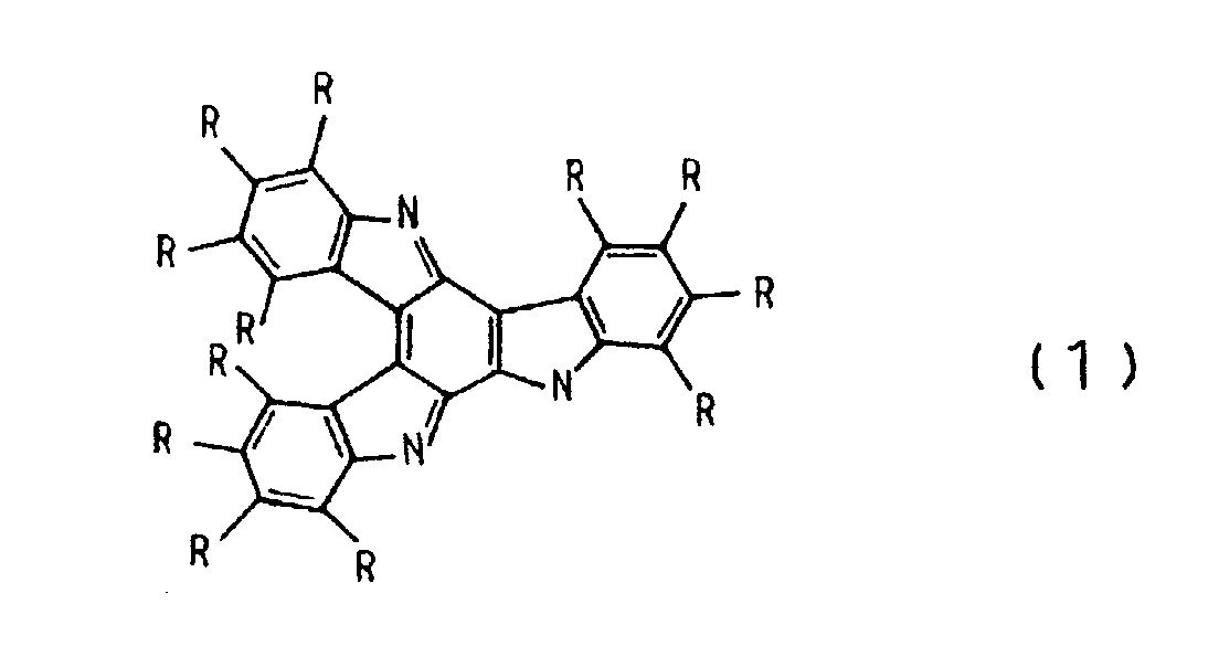
- a cathodic active material may be an indole trimer represented by chemical formula (1): wherein Rs independently represent H, CN, NO 2 , F, COOH, etc.
- An anodic active material may be a polyphenylquinoxaline represented by chemical formula (2):
- An electrode used in this invention may be formed by, for example, placing an electrode material in a mold having a defined size/shape and by molding the material using a hot press.
- an electrode material is mixed with a solvent to give a paste, which is then deposited by printing on a current collector to form an electrode.
- a separator prevents short-circuit caused by contact between a pair of electrodes and allows electrolyte ions to pass through it. It may be a nonwoven fabric or porous film which may be impregnated with an electrolyte.
- An electrolyte may be selected from aqueous acidic solutions such as sulfuric acid; aqueous alkaline solutions such as an aqueous potassium hydroxide solution; and non-aqueous electrolytes such as a mixture of an organic solvent (e. g., propylene carbonate) and an electrolyte (e. g., a quaternary ammonium salt).
- aqueous acidic solutions such as sulfuric acid
- aqueous alkaline solutions such as an aqueous potassium hydroxide solution
- non-aqueous electrolytes such as a mixture of an organic solvent (e. g., propylene carbonate) and an electrolyte (e. g., a quaternary ammonium salt).
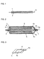
- FIG. 2 shows a schematic cross-section of a battery having a laminated structure as an embodiment of this invention where three basic cells illustrated in FIG. 1 are laminated in series.
- a metal terminal plate 6 in FIG. 2 only its lead 6a is shown and the remaining part is omitted.
- the metal terminal plate 6 may be disposed as illustrated in FIG. 3.
- basic cells are laminated in series via sheet current collectors 4b, and packaged in a resin sheet 5.
- the resin sheet 5 is fluid-tightly glued or fused in a sealing area in its edge to form an outer package.
- the symbol 7 indicates a fusion area.
- This outer package may be a pair of piled resin sheets, which are glued or fused in a sealing area in its edge, or a folded resin sheet glued or fused in a sealing area in its edge.
- a resin sheet is preferably a laminated sheet.
- a laminated sheet having a laminated structure of a resin film and metal film may be used.
- the laminated sheet may have a three layer structure of an outer package resin film, a metal film and a fusing resin film. Alternatively, it may have a four layer structure for, e. g., preventing short-circuit.
- the resin film include a polyethylene resin, an ethylene copolymer resin and a polypropylene resin
- examples of the metal film include aluminum and an aluminum alloy.
- a fusing resin film is preferably a resin exhibiting good heat-sealing performance and adhesiveness to a metal; suitably a polypropylene resin and an ionomer resin which is a type of ethylene copolymer resin.
- a current collector used in this invention may be a rubber sheet which is endowed with electroconductivity by adding, e. g., carbon.
- the current collectors 4b inserted between the basic cells in this invention are disposed such that the basic cells are liquid-tightly separated from each other.
- the current collectors 4b which lie between the basic cells extend to the edge of the resin sheet package around its periphery and glued or fused in the edge of the resin sheet package.
- the edge of the extended part of the current collector piled on the edge of the resin sheet may be simultaneously fused to unite them.
- an insulating resin is inserted between the current collectors for preventing these current collectors from coming into contact each other.
- the resin which may be inserted between the current collectors may be the fusing resin film described above, which can ensure insulation between the current collectors and adequate fusion of the current collector edge piled on the edge of the resin sheet during fusing the edge of the resin sheet.
- a sheet current collector 4a is disposed on the electrode in each of the top and the bottom layers in a laminated structure in which basic cells are laminated and each of these sheet current collectors 4a is glued or fused to the inner surface 5 of the resin sheet package such that it covers the metal terminal plate 6 except its lead 6a as illustrated in FIG. 3.
- a configuration can prevent corrosion of the metal terminal plate due to contact between the metal terminal plate and the acidic electrolyte.
- a battery shown in FIG. 2 was fabricated, which had a laminated structure of three basic cells in series.
- a 10 cm 2 solid electrode was formed by adding a conduction aid and a binder to a cathodic active material, the indole trimer represented by chemical formula (1) (R at 5-position in the indole unit is -CN and the remaining Rs are -H: 5-cyanoindole trimer); stirring and blending the mixture by a blender to give an electrode powder; placing 0.5 g of the powder in a mold; and pressing it by a hot press.
- R at 5-position in the indole unit is -CN and the remaining Rs are -H: 5-cyanoindole trimer
- a 10 cm 2 solid electrode was formed by adding a conduction aid to an anodic active material, the polyphenylquinoxaline represented by chemical formula (2); stirring and blending the mixture by a blender to give an electrode powder; placing 0.5 g of the powder in a mold; and pressing it by a hot press.
- Current collectors 4a, 4b were conductive rubber sheets and laminated sheets 5 were laminates of an aluminum foil and a resin film.
- the surface of a metal terminal plate 6 except a lead 6a was liquid-tightly packaged in the laminated sheet 5 and the current collectors 4a consisting of the conductive rubber sheet.
- This configuration can prevent corrosion of the metal terminal plate due to contact between the metal terminal plate and an acidic electrolyte.
- two sheets were prepared, in which the metal terminal plate 6, the current collector 4a and the laminated sheet 5 are integrated.
- the current collectors 4b consisting of a conductive rubber sheet had such a size that they can be extended to the edge of a laminated sheet package (outer package), and were overlapped in the edge of two laminated sheets, i. e., the sealing area. Furthermore, between the current collectors were inserted ionomer films and these were fused together.
- a volumetric efficiency for the battery of this example (a rate of the volume of the basic cell laminate to that of the outer package consisting of the laminated sheets) was 62.5 %.
- An ESR (equivalent series resistance) for the battery was 60 m ⁇ .
- a time taken until sealing in the battery production was 20 min.
- a volumetric efficiency was improved because of absence of a gasket. Furthermore, since the basic cells could be directly laminated via a sheet of current collector, the number of current collectors could be reduced in comparison with a battery using a gasket and thus a resistance could be correspondingly reduced (reduction in an ESR). A production time could be reduced because the process dispensed with steps associated with a gasket (vulcanization adhesion, cooling, etc.).
- a battery was fabricated as described in Example 1, except that an electrode weight was 1.0 g for both cathode and anode.
- a volumetric efficiency of the battery of Example 2 was 87.5 %.
- An ESR for the battery was 120 m ⁇ .
- a time taken until sealing in the battery production was 20 min.
- a volumetric efficiency was improved; a cell ESR could be reduced; and a production time could be reduced.
- a battery was fabricated as described in Example 1, except that ten basic cells were laminated in series and sealed.
- a volumetric efficiency of the battery of Example 3 was 90.5 %.
- An ESR for the battery was 200 m ⁇ .
- a time taken until sealing in the battery production was 20 min.
- a volumetric efficiency was improved; a cell ESR could be reduced; and a production time could be reduced.
- An electric double layer capacitor having a structure as described in Example 1 was fabricated, except that basic cells in which polarizable electrodes were oppositely placed via a separator, were substituted for the basic cells in the battery in Example 1.
- a polarizable electrode was produced by mixing activated carbon with the appropriate amounts of carbon powders as a conduction aid and a binder, mixing the mixture with a solvent to form a paste, depositing the paste on the current collector by printing to given size and film thickness, and then dried the product at 120 °C for 1 hour.
- a polarizable electrode On one side of the current collector 4a was deposited a polarizable electrode while on both sides of the current collector 4b were polarizable electrodes. These current collectors with the polarizable electrodes were laminated such that the polarizable electrodes were oppositely placed via a separator to form a laminated structure where three basic cells were laminated in series via the current collectors 4b. Then, the laminated structure was packaged in a laminated sheet. Then, to the vacuumed product was added a given amount of 20 wt% aqueous sulfuric acid solution as an electrolyte for impregnation with the electrolyte. Then, a sealing area to be a fused area 7 was sealed by vacuum heat fusion. A lead 6a was drawn outside from a part of the fused area 7.
- the current collectors 4b consisting of a conductive rubber sheet had such a size that they can be extended to the edge of a laminated sheet package (outer package), and were overlapped in the edge of two laminated sheets, i. e., the sealing area. Furthermore, between the current collectors were inserted ionomer films and these were fused together.
- a volumetric efficiency for the electric double layer capacitor of Example 4 was 62.5 %.
- An ESR for the electric double layer capacitor was 45 m ⁇ .
- a time taken until sealing in the production was 110 min.
- a volumetric, efficiency was improved; a capacitor ESR could be reduced; and a production time could be reduced.
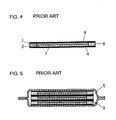
- FIG. 5 a battery (FIG. 5) where three unit cells (FIG. 4) comprising one basic cell were laminated in series, was fabricated.
- a cathode 1 with a size of 10 cm 2 was formed by adding an appropriate amount of carbon powders as a conduction aid to a cathodic active material, the cyanoindole trimer represented by chemical formula (1) (R at 5-position in the indole unit is -CN and the remaining Rs are -H: 5-cyanoindole trimer) and pressing 0.5 g of the powders by a hot press.
- the cyanoindole trimer represented by chemical formula (1) (R at 5-position in the indole unit is -CN and the remaining Rs are -H: 5-cyanoindole trimer) and pressing 0.5 g of the powders by a hot press.
- An anode 2 with a size of 10 cm 2 was formed by adding an appropriate amount of carbon powders as a conduction aid to an anodic active material, the polyphenylquinoxaline represented by chemical formula (2) and pressing 0.5 g of the powders by a hot press.
- a rim type gasket 8 was fused by pressure with one current collector 4 consisting of a conductive rubber sheet. Inside of the gasket, a cathode 1 and an anode 2 were oppositely placed via a separator 3. Over the product was placed the other current collector 4 consisting of a conductive rubber sheet and the laminate was sealed by pressing. In this process, sealing was conducted while forming an inlet for injecting an electrolyte.
- the product was subject to vulcanization adhesion at 120 °C at a pressure of 3 kgf/cm 2 (2.94 x 10 5 Pa) for 2 hours. Then, a 20 wt% aqueous sulfuric acid solution as an electrolyte was injected into the vacuumed product for impregnation with the electrolyte. Then, the inlet was sealed with a plastic material.
- Three unit cells thus prepared were laminated in series. On both sides of the laminate were disposed metal terminal plates. The laminate was then packaged in a laminated sheet and was sealed by vacuum hot fusion using an ionomer fusion film. From a part of the fused area, a lead (not shown) was drawn outside.
- a volumetric efficiency for the battery in Comparative Example 1 was 33.1 %.
- a battery ESR was 68 m ⁇ .
- a time taken until sealing in the production was 205 min.
- a battery was fabricated as described in Comparative Example 1 except that an electrode weight was 1.0 g for both cathode and anode.
- a volumetric efficiency for the battery in Comparative Example 2 was 39.7 %.
- a battery ESR was 136 m ⁇ .
- a time taken until sealing in the production was 205 min.
- a battery was fabricated as described in Comparative Example 1 except that ten unit cells were laminated in series and sealed.
- a volumetric efficiency for the battery in Comparative Example 3 was 39.7 %.
- a battery ESR was 212 m ⁇ .
- a time taken until sealing in the production was 205 min.
- An electric double layer capacitor was fabricated as described in Comparative Example 1, except that basic cells in which polarizable electrodes were oppositely placed via a separator, were substituted for the basic cells in the battery in Comparative Example 1.
- a polarizable electrode was produced by mixing activated carbon with the appropriate amounts of carbon powders as a conduction aid and a binder, mixing the mixture with a solvent to form a paste, depositing the paste on the current collector by printing to given size and film thickness, and then dried the product at 120 °C for 1 hour.
- a volumetric efficiency for the battery in Comparative Example 4 was 33.1 %.
- An ESR of the electric double layer capacitor was 53 m ⁇ .
- a time taken until sealing in the production was 205 min.
- Example 1 Volumetric efficiency (%) ESR (m ⁇ ) Production time (min)
- Example 1 62.5 60 20
- Example 4 62.5 45 110 Comp.
- Example 4 33.1 53 205 Examples 1 to 3 Step 1 5 min
- Metal terminal plates are packaged in a laminate of a conductive rubber sheet and a laminated sheet, and their sheet are fused and sealed by heat.
- Step 2 5 min An electrode is formed by hot press molding.
- Step 3 5 min A laminate of basic cells is formed within a laminated sheet package.
- Step 4 5 min An electrolyte is injected and sealing is conducted.
- Step 1 5 min Metal terminal plates are packaged in a laminate of a conductive rubber sheet and a laminated sheet, and their sheet are fused and sealed by heat.
- Step 2 5 min A polarizable electrode is deposited on a current collector.
- Step 3 90 min The product was dried at 120 °C and cooled.
- Step 4 5 min A laminate of basic cells is formed within a laminated sheet package.
- Step 5 5 min An electrolyte is injected and sealing is conducted.
- Total 110 min Comparative Examples 1 to 3 Step 1 5 min An electrode is formed by hot press molding.
- Step 2 5 min A gasket and one current collector are fused by pressure. Inside gasket, basic cells are formed. On the gasket is pressure-fused the other current collector for sealing.
- Step 3 120 min The gasket and the current collectors are subject to vulcanization adhesion at 120 °C.
- Step 4 60 min The product is cooled.
- Step 5 10 min An electrolyte is injected and an inlet is sealed.
- Step 6 5 min Metal terminal plates are disposed. The product is packaged in a laminated sheet and sealed. Total 205 min Comparative Example 4
- Step 1 5 min A polarizable electrode is deposited on a current collector.
- Step 2 5 min A gasket and one current collector deposited are fused by pressure. Inside the gasket, a separator is placed on the electrode. On the gasket is pressure-fused the other current collector for sealing.
- Step 3 120 min The gasket and the current collectors are subject to vulcanization adhesion at 120 °C.
- Step 4 60 min The product is cooled.
- Step 5 10 min An electrolyte is injected and an inlet is sealed.
- Step 6 5 min Metal terminal plates are disposed. The product is packaged in a laminated
Landscapes
- Engineering & Computer Science (AREA)
- Power Engineering (AREA)
- Chemical & Material Sciences (AREA)
- Chemical Kinetics & Catalysis (AREA)
- Electrochemistry (AREA)
- General Chemical & Material Sciences (AREA)
- Microelectronics & Electronic Packaging (AREA)
- Manufacturing & Machinery (AREA)
- Electric Double-Layer Capacitors Or The Like (AREA)
- Sealing Battery Cases Or Jackets (AREA)
- Connection Of Batteries Or Terminals (AREA)
- Primary Cells (AREA)
- Secondary Cells (AREA)
Abstract
Description
the basic cells are laminated in series via a sheet current collector;
the sheet current collector extends to an edge of the resin sheet package around the periphery of the basic cells laminated on both sides of the current collector;
the sheet current collector is glued or fused to the resin sheet in its edge; and
the adjacent basic cells via the sheet current collector are fluid-tightly separated within the resin sheet package.
at each of the top side and the bottom side of a laminated structure comprising the laminated basic cells, is disposed a metal terminal plate with a lead extending to the outside of resin sheet package;
each of the top side and the bottom side of the laminated structure has a sheet current collector, which is connected to the internal surface of the resin sheet package such that the sheet current collector covers the metal terminal plate except its lead.
the basic cells are laminated in series via a sheet current collector;
the sheet current collector extends to an edge of the resin sheet package around the periphery of the basic cells laminated on both sides of the current collector;
the sheet current collector is connected to the resin sheet in its edge; and
the adjacent basic cells via the sheet current collector are fluid-tightly separated within the resin sheet package.
wherein
at each of the top side and the bottom side of a laminated structure comprising the laminated basic cells, is disposed a metal terminal plate with a lead extending to the outside of resin sheet package;
each of the top side and the bottom side of the laminated structure has a sheet current collector, which is connected to the internal surface of the resin sheet package such that the sheet current collector covers the metal terminal plate except its lead.

| Volumetric efficiency (%) | ESR (mΩ) | Production time (min) | |
| Example 1 | 62.5 | 60 | 20 |
| Example 2 | 87.5 | 120 | 20 |
| Example 3 | 90.5 | 200 | 20 |
| Example 4 | 62.5 | 45 | 110 |
| Comp. Example 1 | 33.1 | 68 | 205 |
| Comp. Example 2 | 39.7 | 136 | 205 |
| Comp. Example 3 | 39.7 | 212 | 205 |
| Comp. Example 4 | 33.1 | 53 | 205 |
| Examples 1 to 3 | ||
| | 5 min | Metal terminal plates are packaged in a laminate of a conductive rubber sheet and a laminated sheet, and their sheet are fused and sealed by heat. |
| | 5 min | An electrode is formed by hot press molding. |
| | 5 min | A laminate of basic cells is formed within a laminated sheet package. |
| | 5 min | An electrolyte is injected and sealing is conducted. |
| Total | 20 min |
| Example 4 | ||
| | 5 min | Metal terminal plates are packaged in a laminate of a conductive rubber sheet and a laminated sheet, and their sheet are fused and sealed by heat. |
| | 5 min | A polarizable electrode is deposited on a current collector. |
| | 90 min | The product was dried at 120 °C and cooled. |
| | 5 min | A laminate of basic cells is formed within a laminated sheet package. |
| | 5 min | An electrolyte is injected and sealing is conducted. |
| Total | 110 min |
| Comparative Examples 1 to 3 | ||
| | 5 min | An electrode is formed by hot press molding. |
| | 5 min | A gasket and one current collector are fused by pressure. Inside gasket, basic cells are formed. On the gasket is pressure-fused the other current collector for sealing. |
| | 120 min | The gasket and the current collectors are subject to vulcanization adhesion at 120 ° |
| Step | ||
| 4 | 60 min | The product is cooled. |
| | 10 min | An electrolyte is injected and an inlet is sealed. |
| Step 6 | 5 min | Metal terminal plates are disposed. The product is packaged in a laminated sheet and sealed. |
| Total | 205 min |
| Comparative Example 4 | ||
| | 5 min | A polarizable electrode is deposited on a current collector. |
| | 5 min | A gasket and one current collector deposited are fused by pressure. Inside the gasket, a separator is placed on the electrode. On the gasket is pressure-fused the other current collector for sealing. |
| | 120 min | The gasket and the current collectors are subject to vulcanization adhesion at 120 ° |
| Step | ||
| 4 | 60 min | The product is cooled. |
| | 10 min | An electrolyte is injected and an inlet is sealed. |
| Step 6 | 5 min | Metal terminal plates are disposed. The product is packaged in a laminated sheet and sealed. |
| Total | 205 min |
Claims (6)
- A battery including a plurality of cells each comprising a separator (3), a cathode (1) and an anode (2) oppositely laminated via the separator (3), and electrolyte and a resin sheet package (5), wherein
the cells are laminated in series via sheet current collector (4a, 4b);
the sheet current collector (4a, 4b) extends to an edge of the resin sheet package (5) around the periphery of the cells laminated on both sides of the current collector (4a, 4b);
the sheet current collector (4a, 4b) is glued or fused to the resin sheet (5) at its edge; and wherein
the adjacent cells via the sheet current collector (4a, 4b) are fluid-tightly separated within the resin sheet package. - A battery as claimed in Claim 1, wherein
at each of a top side and a bottom side of the laminated structure comprising the laminated cells, there is disposed a metal terminal plate (6) with a lead extending to the outside of resin sheet package; and wherein
each of the top side and the bottom side of the laminated structure has a sheet current collector (4a, 4b), which is glued or fused to the internal surface of the resin sheet package such that the sheet current collector (4a, 4b) covers the metal terminal plate (6) except its lead. - A battery as claimed in Claim 1 or 2, wherein the resin sheet (5) is a laminated sheet consisting of a resin film and a metal film.
- An electric double layer capacitor including a plurality of cells each comprising a pair of polarizable electrodes oppositely laminated via the separator, an electrolyte and a resin sheet package, wherein
the cells are laminated in series via a sheet current collector;
the sheet current collector extends to an edge of the resin sheet package around the periphery of the cells laminated on both sides of the current collector;
the sheet current collector is glued or fused to the resin sheet at its edge; and wherein
the adjacent cells via the sheet current collector are fluid-tightly separated within the resin sheet package. - A capacitor as claimed in Claim 4, wherein
at each of a top side and a bottom side of the laminated structure comprising the laminated cells, there is disposed a metal terminal plate with a lead extending to the outside of resin sheet package; and wherein
each of the top side and the bottom side of the laminated structure has a sheet current collector, which is glued or fused to the internal surface of the resin sheet package such that the sheet current collector covers the metal terminal plate except its lead. - A capacitor as claimed in Claim 4 or 5, wherein the resin sheet comprises a laminated sheet consisting of a resin film and a metal film.
Applications Claiming Priority (2)
| Application Number | Priority Date | Filing Date | Title |
|---|---|---|---|
| JP2002011506 | 2002-01-21 | ||
| JP2002011506A JP3953327B2 (en) | 2002-01-21 | 2002-01-21 | Batteries and electric double layer capacitors |
Publications (2)
| Publication Number | Publication Date |
|---|---|
| EP1331677A2 true EP1331677A2 (en) | 2003-07-30 |
| EP1331677A3 EP1331677A3 (en) | 2005-07-20 |
Family
ID=19191680
Family Applications (1)
| Application Number | Title | Priority Date | Filing Date |
|---|---|---|---|
| EP03250290A Withdrawn EP1331677A3 (en) | 2002-01-21 | 2003-01-17 | Battery and electric double layer capacitor |
Country Status (6)
| Country | Link |
|---|---|
| US (1) | US6998190B2 (en) |
| EP (1) | EP1331677A3 (en) |
| JP (1) | JP3953327B2 (en) |
| KR (1) | KR100497560B1 (en) |
| CN (1) | CN1217430C (en) |
| TW (1) | TWI221679B (en) |
Cited By (3)
| Publication number | Priority date | Publication date | Assignee | Title |
|---|---|---|---|---|
| GB2477552A (en) * | 2010-02-08 | 2011-08-10 | Qinetiq Ltd | Thin Electrochemical Cell |
| WO2012050818A1 (en) * | 2010-10-13 | 2012-04-19 | Cooper Technologies Company | High voltage electric double layer capacitor device and methods of manufacture |
| FR2977971A1 (en) * | 2011-07-13 | 2013-01-18 | Hutchinson | SUPERCONDENSER CELL AND SUPERCAPACITIVE MODULE INCORPORATING A PLURALITY OF THESE CELLS. |
Families Citing this family (19)
| Publication number | Priority date | Publication date | Assignee | Title |
|---|---|---|---|---|
| JP4396319B2 (en) * | 2004-02-25 | 2010-01-13 | Tdk株式会社 | Method for manufacturing electrochemical device |
| KR100669446B1 (en) | 2005-07-07 | 2007-01-16 | 주식회사로케트전기 | Manufacturing method of series connected ultra thin manganese battery |
| US7580244B2 (en) * | 2005-12-26 | 2009-08-25 | Tdk Corporation | Electrochemical device and method for manufacturing same, and jig for manufacturing electrochemical device |
| JPWO2007111070A1 (en) * | 2006-03-29 | 2009-08-06 | 日産化学工業株式会社 | Composition for electrode of energy storage device and method for producing the same |
| US20080198565A1 (en) * | 2007-02-16 | 2008-08-21 | Tyco Electronics Corporation | Surface mount foot with coined edge surface |
| KR101115382B1 (en) * | 2007-07-23 | 2012-02-15 | 주식회사 엘지화학 | High power secondary battery with series connection structure |
| EP2276043B1 (en) * | 2008-03-18 | 2012-11-21 | Taiyo Yuden Co., Ltd. | Electrochemical device |
| JP2012104804A (en) * | 2010-10-15 | 2012-05-31 | Seiko Instruments Inc | Electronic component and electronic device |
| KR101578265B1 (en) | 2013-02-26 | 2015-12-16 | 주식회사 엘지화학 | Bi-cell for secondary battery with improved stability and manufacturing method thereof |
| US20150037621A1 (en) * | 2013-07-24 | 2015-02-05 | Empire Technology Development Llc | Energy storage device |
| US10312028B2 (en) * | 2014-06-30 | 2019-06-04 | Avx Corporation | Electrochemical energy storage devices and manufacturing methods |
| US10468203B2 (en) * | 2015-08-25 | 2019-11-05 | Arizona Board Of Regents On Behalf Of Arizona State University | Edible supercapacitors |
| CN105406086B (en) * | 2015-10-28 | 2018-09-11 | 广东烛光新能源科技有限公司 | Electrochemical cell and preparation method thereof |
| CN106067740B (en) * | 2016-05-25 | 2019-02-15 | 纳智源科技(唐山)有限责任公司 | Triboelectricity device and preparation method thereof |
| US11830672B2 (en) | 2016-11-23 | 2023-11-28 | KYOCERA AVX Components Corporation | Ultracapacitor for use in a solder reflow process |
| CN106960976A (en) * | 2017-05-05 | 2017-07-18 | 杭州金色能源科技有限公司 | Thin-type secondary battery and preparation method thereof |
| KR102529492B1 (en) * | 2017-11-17 | 2023-05-04 | 현대자동차주식회사 | All-solid battery and method for manufacturing the same |
| US10842438B2 (en) | 2018-02-20 | 2020-11-24 | Arizona Board Of Regents On Behalf Of Arizona State University | Swallowable, food-based, digestible wireless device for measuring gastric pH |
| KR102541537B1 (en) * | 2019-06-25 | 2023-06-08 | 주식회사 엘지에너지솔루션 | Battery module and battery pack including the same |
Family Cites Families (20)
| Publication number | Priority date | Publication date | Assignee | Title |
|---|---|---|---|---|
| JPS603867A (en) * | 1983-06-22 | 1985-01-10 | Seiko Instr & Electronics Ltd | Flat type battery |
| JPS6097545A (en) * | 1983-11-01 | 1985-05-31 | Seiko Instr & Electronics Ltd | flat plate battery |
| JPH063735B2 (en) * | 1984-10-09 | 1994-01-12 | 凸版印刷株式会社 | Flat plate battery |
| JPS63121244A (en) * | 1986-11-11 | 1988-05-25 | Dainippon Printing Co Ltd | flexible thin battery |
| JPH04237109A (en) | 1991-01-22 | 1992-08-25 | Nec Corp | Electric double-layer capacitor and manufacture thereof |
| JP3125341B2 (en) * | 1991-08-20 | 2001-01-15 | 株式会社村田製作所 | Multilayer electric double layer capacitors |
| JPH0629154A (en) | 1992-07-10 | 1994-02-04 | Isuzu Motors Ltd | Output terminal of electric double layer capacitor |
| JP3200488B2 (en) * | 1993-01-19 | 2001-08-20 | 沖電気工業株式会社 | Resin-sealed semiconductor device and method of manufacturing the same |
| JPH07240347A (en) | 1994-02-28 | 1995-09-12 | Fuji Elelctrochem Co Ltd | Coin type electric double layer capacitor and method for manufacturing the same |
| JPH0878291A (en) | 1994-08-31 | 1996-03-22 | Hyogo Nippon Denki Kk | Electric double layer capacitor and manufacturing method thereof |
| JP3617081B2 (en) | 1994-09-09 | 2005-02-02 | ソニー株式会社 | Thin card battery |
| JP3775633B2 (en) | 1999-02-16 | 2006-05-17 | 日立マクセル株式会社 | Stacked polymer electrolyte battery |
| JP4377475B2 (en) | 1999-04-14 | 2009-12-02 | 株式会社東芝 | Thin battery |
| JP3470672B2 (en) | 2000-02-01 | 2003-11-25 | 日本電気株式会社 | Electric double layer capacitor and method of manufacturing the same |
| JP3422745B2 (en) | 2000-02-28 | 2003-06-30 | エヌイーシートーキン株式会社 | Electric double layer capacitor |
| JP2001250742A (en) * | 2000-03-07 | 2001-09-14 | Nec Corp | Electric double layer capacitor and its manufacturing method |
| JP2001332241A (en) | 2000-05-23 | 2001-11-30 | Sony Corp | Thin battery |
| JP3497448B2 (en) * | 2000-06-09 | 2004-02-16 | Necトーキン株式会社 | Electric double layer capacitors and batteries |
| KR100430123B1 (en) * | 2000-12-28 | 2004-05-03 | 마쯔시다덴기산교 가부시키가이샤 | Nonaqueous electrolyte battery and production method therefor |
| JP2002298798A (en) | 2001-04-02 | 2002-10-11 | Nec Tokin Corp | Battery, electric double layer capacitor, method of manufacturing battery, and method of manufacturing electric double layer capacitor |
-
2002
- 2002-01-21 JP JP2002011506A patent/JP3953327B2/en not_active Expired - Fee Related
-
2003
- 2003-01-17 EP EP03250290A patent/EP1331677A3/en not_active Withdrawn
- 2003-01-17 US US10/346,102 patent/US6998190B2/en not_active Expired - Lifetime
- 2003-01-20 KR KR10-2003-0003631A patent/KR100497560B1/en not_active Expired - Fee Related
- 2003-01-21 TW TW092101293A patent/TWI221679B/en not_active IP Right Cessation
- 2003-01-21 CN CN031006809A patent/CN1217430C/en not_active Expired - Lifetime
Cited By (7)
| Publication number | Priority date | Publication date | Assignee | Title |
|---|---|---|---|---|
| GB2477552A (en) * | 2010-02-08 | 2011-08-10 | Qinetiq Ltd | Thin Electrochemical Cell |
| GB2477552B (en) * | 2010-02-08 | 2016-01-27 | Qinetiq Ltd | Thin electrochemical cell |
| US10777782B2 (en) | 2010-02-08 | 2020-09-15 | Qinetiq Limited | Thin electrochemical cell |
| WO2012050818A1 (en) * | 2010-10-13 | 2012-04-19 | Cooper Technologies Company | High voltage electric double layer capacitor device and methods of manufacture |
| US8508916B2 (en) | 2010-10-13 | 2013-08-13 | Cooper Technologies Company | High voltage electric double layer capacitor device and methods of manufacture |
| FR2977971A1 (en) * | 2011-07-13 | 2013-01-18 | Hutchinson | SUPERCONDENSER CELL AND SUPERCAPACITIVE MODULE INCORPORATING A PLURALITY OF THESE CELLS. |
| EP2557579A1 (en) * | 2011-07-13 | 2013-02-13 | Hutchinson | Supercapacitor cell and supercapacitor module including a plurality of these cells. |
Also Published As
| Publication number | Publication date |
|---|---|
| US6998190B2 (en) | 2006-02-14 |
| CN1434531A (en) | 2003-08-06 |
| HK1057131A1 (en) | 2004-03-12 |
| KR100497560B1 (en) | 2005-06-28 |
| KR20030063205A (en) | 2003-07-28 |
| US20030165735A1 (en) | 2003-09-04 |
| JP3953327B2 (en) | 2007-08-08 |
| CN1217430C (en) | 2005-08-31 |
| TW200302587A (en) | 2003-08-01 |
| JP2003217646A (en) | 2003-07-31 |
| TWI221679B (en) | 2004-10-01 |
| EP1331677A3 (en) | 2005-07-20 |
Similar Documents
| Publication | Publication Date | Title |
|---|---|---|
| US6998190B2 (en) | Battery having a sheet current collector fluid-tightly separating basic cells | |
| KR101050012B1 (en) | Hybrid energy storage device and manufacturing method thereof | |
| JP3397351B2 (en) | Prismatic or sheet type battery and manufacturing method thereof | |
| JP2019135719A (en) | Bipolar battery assembly | |
| CN1331249C (en) | Storage battery | |
| JP2019009130A (en) | Thin electrochemical cell | |
| CN100353592C (en) | Laminated battery | |
| CN1421051A (en) | Electrochemical energy storage device having improved enclosure arrangement | |
| US6664619B2 (en) | Laminate film packaged storage device and fabricating method thereof | |
| WO2002071529A1 (en) | Nonaqueous electrolyte secondary battery and its producing method | |
| JP2019087534A (en) | Bipolar battery assembly | |
| US20050122664A1 (en) | Method of producing electrochemical device, and the electrochemical device | |
| JP2004355823A (en) | Hybrid type electricity storage component | |
| KR20140012601A (en) | Secondary battery and electrochemical cell having the same | |
| US20160093919A1 (en) | Vanadium Solid-Salt Battery | |
| CN109888162A (en) | Have gluing structure battery core of embedded tab and preparation method thereof and lithium battery | |
| CN106025169B (en) | Electric storage element | |
| KR20140013177A (en) | Secondary battery and electrochemical cell having the same | |
| KR101128565B1 (en) | Electrochemical capacitor and method of manufacturing the same | |
| KR20120123851A (en) | Electrode assembly including anode and cathod electrode more than 2 and electrochemical device using the same | |
| KR100955233B1 (en) | Stacked Electrical Double Layer Capacitors | |
| JP2012033277A (en) | Laminated type secondary battery | |
| CN114365331A (en) | Electric storage element, method for manufacturing electric storage element, and method for designing electric storage element | |
| JP3676075B2 (en) | Thin battery and manufacturing method thereof | |
| KR20250049956A (en) | Bipolar battery |
Legal Events
| Date | Code | Title | Description |
|---|---|---|---|
| PUAI | Public reference made under article 153(3) epc to a published international application that has entered the european phase |
Free format text: ORIGINAL CODE: 0009012 |
|
| AK | Designated contracting states |
Designated state(s): AT BE BG CH CY CZ DE DK EE ES FI FR GB GR HU IE IT LI LU MC NL PT SE SI SK TR |
|
| AX | Request for extension of the european patent |
Extension state: AL LT LV MK RO |
|
| PUAL | Search report despatched |
Free format text: ORIGINAL CODE: 0009013 |
|
| AK | Designated contracting states |
Kind code of ref document: A3 Designated state(s): AT BE BG CH CY CZ DE DK EE ES FI FR GB GR HU IE IT LI LU MC NL PT SE SI SK TR |
|
| AX | Request for extension of the european patent |
Extension state: AL LT LV MK RO |
|
| RIC1 | Information provided on ipc code assigned before grant |
Ipc: 7H 01G 9/10 B Ipc: 7H 01G 9/08 B Ipc: 7H 01G 9/00 B Ipc: 7H 01M 10/04 B Ipc: 7H 01M 6/40 B Ipc: 7H 01M 2/02 A |
|
| 17P | Request for examination filed |
Effective date: 20050613 |
|
| AKX | Designation fees paid |
Designated state(s): DE GB |
|
| STAA | Information on the status of an ep patent application or granted ep patent |
Free format text: STATUS: THE APPLICATION IS DEEMED TO BE WITHDRAWN |
|
| 18D | Application deemed to be withdrawn |
Effective date: 20100803 |