EP1331490A1 - Sound source probing system - Google Patents
Sound source probing system Download PDFInfo
- Publication number
- EP1331490A1 EP1331490A1 EP01972633A EP01972633A EP1331490A1 EP 1331490 A1 EP1331490 A1 EP 1331490A1 EP 01972633 A EP01972633 A EP 01972633A EP 01972633 A EP01972633 A EP 01972633A EP 1331490 A1 EP1331490 A1 EP 1331490A1
- Authority
- EP
- European Patent Office
- Prior art keywords
- sound source
- microphones
- sound
- location
- locating system
- Prior art date
- Legal status (The legal status is an assumption and is not a legal conclusion. Google has not performed a legal analysis and makes no representation as to the accuracy of the status listed.)
- Granted
Links
Images


Classifications
-
- G—PHYSICS
- G01—MEASURING; TESTING
- G01S—RADIO DIRECTION-FINDING; RADIO NAVIGATION; DETERMINING DISTANCE OR VELOCITY BY USE OF RADIO WAVES; LOCATING OR PRESENCE-DETECTING BY USE OF THE REFLECTION OR RERADIATION OF RADIO WAVES; ANALOGOUS ARRANGEMENTS USING OTHER WAVES
- G01S3/00—Direction-finders for determining the direction from which infrasonic, sonic, ultrasonic or electromagnetic waves, or particle emission, not having a directional significance, are being received
- G01S3/80—Direction-finders for determining the direction from which infrasonic, sonic, ultrasonic or electromagnetic waves, or particle emission, not having a directional significance, are being received using ultrasonic, sonic or infrasonic waves
- G01S3/802—Systems for determining direction or deviation from predetermined direction
- G01S3/808—Systems for determining direction or deviation from predetermined direction using transducers spaced apart and measuring phase or time difference between signals therefrom, i.e. path-difference systems
- G01S3/8083—Systems for determining direction or deviation from predetermined direction using transducers spaced apart and measuring phase or time difference between signals therefrom, i.e. path-difference systems determining direction of source
-
- G—PHYSICS
- G01—MEASURING; TESTING
- G01H—MEASUREMENT OF MECHANICAL VIBRATIONS OR ULTRASONIC, SONIC OR INFRASONIC WAVES
- G01H3/00—Measuring characteristics of vibrations by using a detector in a fluid
-
- G—PHYSICS
- G01—MEASURING; TESTING
- G01H—MEASUREMENT OF MECHANICAL VIBRATIONS OR ULTRASONIC, SONIC OR INFRASONIC WAVES
- G01H3/00—Measuring characteristics of vibrations by using a detector in a fluid
- G01H3/10—Amplitude; Power
- G01H3/12—Amplitude; Power by electric means
-
- G—PHYSICS
- G01—MEASURING; TESTING
- G01S—RADIO DIRECTION-FINDING; RADIO NAVIGATION; DETERMINING DISTANCE OR VELOCITY BY USE OF RADIO WAVES; LOCATING OR PRESENCE-DETECTING BY USE OF THE REFLECTION OR RERADIATION OF RADIO WAVES; ANALOGOUS ARRANGEMENTS USING OTHER WAVES
- G01S5/00—Position-fixing by co-ordinating two or more direction or position line determinations; Position-fixing by co-ordinating two or more distance determinations
- G01S5/18—Position-fixing by co-ordinating two or more direction or position line determinations; Position-fixing by co-ordinating two or more distance determinations using ultrasonic, sonic or infrasonic waves
- G01S5/20—Position of source determined by a plurality of spaced direction-finders
-
- G—PHYSICS
- G01—MEASURING; TESTING
- G01S—RADIO DIRECTION-FINDING; RADIO NAVIGATION; DETERMINING DISTANCE OR VELOCITY BY USE OF RADIO WAVES; LOCATING OR PRESENCE-DETECTING BY USE OF THE REFLECTION OR RERADIATION OF RADIO WAVES; ANALOGOUS ARRANGEMENTS USING OTHER WAVES
- G01S5/00—Position-fixing by co-ordinating two or more direction or position line determinations; Position-fixing by co-ordinating two or more distance determinations
- G01S5/18—Position-fixing by co-ordinating two or more direction or position line determinations; Position-fixing by co-ordinating two or more distance determinations using ultrasonic, sonic or infrasonic waves
- G01S5/22—Position of source determined by co-ordinating a plurality of position lines defined by path-difference measurements
Definitions
- the present invention relates to a sound source locating system for locating the source of a noise and displaying the location of the source to cope with noises at a factory or the like.
- Conventionally proposed sound source locating methods include (1) one making use of the correlation between sound pressure waveforms and (2) one making use of acoustic holography.
- the property of a correlation function is utilized to estimate the location of a sound source from the correlation between sound waveforms collected at a plurality of locations whereas in the method (2), a basic wave is scanned in a space to be investigated, an interference sound generated by interference between the above basic wave and a noise is recorded for each scanning direction, and a sound pressure distribution in the space in which the basic wave has been scanned is reproduced from the obtained record to estimate the source of the noise.
- a sound source is located using a directional microphone. Since most noises at a factory or the like are sounds having a low frequency range as described above, they have low directionability and even when a microphone is provided with directionability, it is difficult to locate a sound source.
- a sound source locating system which comprises microphones including three microphones arranged two-dimensionally, means of estimating the location of a sound source from phase differences among the output signals of the microphones (such as information on the phase angle of the cross spectrum of the output signals), means of picking up an image around the estimated location of the sound source and means of displaying the above estimated location of the sound source on the picked up image in order to estimate the location of the sound source and display the estimated location of the sound source on the image around the location of the sound source displayed on the display means such as a display.
- a sound source locating system which comprises microphones including four microphones arranged three-dimensionally, means of estimating the location of a sound source from phase differences among the output signals of the microphones, means of picking up an image around the estimated location of the sound source and means of displaying the estimated location of the sound source on the picked up image.
- a sound source locating system wherein a pair of microphones spaced apart from each other by a predetermined distance are each disposed on three crossing straight lines, a difference between sound arrival times to each pair of microphones is obtained, and the location of the sound source is estimated from the above arrival time differences.
- a sound source locating system which comprises microphones consisting of two pairs of microphones disposed on two crossing straight lines with a predetermined distance therebetween and a fifth microphone not existent on the same plane as the above two pairs of microphones, means of estimating the location of a sound source from phase differences among the output signals of the microphones, means of picking up an image around the estimated location of the sound source and means of displaying the estimated location of the sound source on the picked up image in order to estimate the location of the sound source from differences among sound arrival times to the microphones obtained from the above phase differences and display the estimated location of the sound source on the image around the location of the sound source displayed on the display means such as a display.
- a sound source locating system wherein the above two pairs of microphones are disposed on two crossing straight lines, respectively, to form a regular square, the fifth microphone is disposed on a straight line passing through the center of the regular square and perpendicular to the above two straight lines to make the distances between the fifth microphone and the microphones forming the square equal to one another, and differences among sound arrival times to the microphones are obtained to estimate the location of the sound source.
- a sound source locating system wherein the fifth microphone is arranged such that the distances between the fifth microphone and the other microphones forming the regular square are made equal to the distance between each pair of the microphones.
- a sound source locating system wherein the color of a symbol for the location of the sound source displayed is changed according to the level of sound pressure or the height of frequency.
- a sound source locating system wherein the microphones are moved to a plurality of positions, thereby improving the estimation accuracy of the location of the sound source.
- a sound source locating system wherein the microphones are rotated to collect sounds at a plurality of angles, thereby improving the estimation accuracy of the location of the sound source.
- a sound source locating system wherein the microphones are used to collect a sound at predetermined time intervals to obtain the location of the sound source at each measurement time in order to estimate the movement of the location of the sound source.
- a sound source locating system which comprises means of measuring the absolute locations on the ground of the microphones to specify the absolute location on the ground of the sound source from the measurement locations of the microphones.
- a sound source locating system which comprises means of storing data on the sound pressure of a sound source which is collected by the microphones and normal and means of comparing newly collected sound pressure data with the above stored sound pressure data.
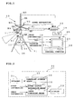
- Fig. 1 is a schematic diagram of a sound source locating system according to Embodiment 1.
- M1 to M4 are microphones for measuring the sound pressure level of a noise from an unshown sound source
- M0 is an auxiliary measuring microphone
- 11 a CCD camera for picking up an image around the location of the sound source (to be simply referred to as "camera” hereinafter)
- 12 GPS for specifying the ground positions of the above microphones M0 to M4
- 13 amplifier for amplifying sound pressure signals collected by the above microphones M0 to M4
- 14 A/D converter for converting the amplified sound pressure signals (analog signals) into digital signals
- 15 a video input/output unit for converting the image signal (analog signal) of the camera 11 into a digital signal.
- Denoted by 20 is a personal computer which comprises a keyboard 21 as input means, a storing/computing unit 22 for computing the estimation of the location of the sound source and a display 23 as image display means.
- the above storing/computing unit 22 comprises parameter storage means 24 for storing measurement parameters, sound source location estimating means 25 for estimating the location of the sound source by a hyperbolic technique using the A/D converted sound pressure signals of the microphones M1 to M4 and image composing means 26 for composing an image by adding an image showing the estimated location of the sound source to an image from the above camera 11 and sending it to the above display 23.
- a base which comprises a support member 31 composed of a tripod and a rotary frame 32, disposed on the top of the support member 31, for mounting the microphones M0 to M4, the microphone M0 is mounted to the top of a vertical frame 32Z projecting upward from the rotary plate 32P of the above rotary frame 32, and the microphones M1 to M4 are mounted to both ends of two horizontal frames 32X and 32Y crossing each other and projecting from the above vertical frame 32Z.
- the camera 11 is mounted to a lower portion of the above vertical frame 32Z and rotated together with the above microphones M0 to M4.
- GPS 12 is mounted on a mounting plate 33 attached below the above rotary frame 32.
- the base 30 mounting the above microphones M0 to M4, the camera 11 and GPS12 is called “measurement unit 10" hereinafter.
- the hyperbolic technique is used to estimate the location of the above sound source, making use of the fact that the location (x, y, z) of the sound source is on the surface of a spindle whose axis is a straight line passing through a pair of microphones (Mi, Mj) and which is determined by a constant calculated from a difference between sound arrival times to the pair of microphones at a predetermined distance from the sound source (time delay Dij), a distance between the microphones and sound velocity.
- a pair of microphones spaced apart from each other by a predetermined distance are each disposed on three crossing straight lines to obtain a difference between sound arrival times to each pair of microphones, and at least three spindles are obtained from the above arrival time differences to obtain the location (x, y, z) of the sound source from the intersecting point of these spindles.
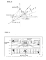
- the direction of the sound source is estimated based on the assumption that the sound source is situated on the X-Y plane. Therefore, as shown in Figs. 3(a) and 3(b), a pair of microphones (M1, M3) and another pair of microphones (M2, M4) are placed at points (L/2, 0, 0) and (-L/2, 0,0) on the X axis and at points (0, L/2, 0) and (0, -L/2, 0) on the Y axis with a distance L therebetween, respectively, and the frequencies of output signals from the pairs of microphones (M1, M3) and (M2, M4)are analyzed to estimate the location of the sound source from a time delay Dij (differences Dx and Dy between sound arrival times to the pair of microphones (M1, M3) and between sound arrival times to the pair of microphones (M2, M4) in this embodiment) between the microphone Mi and the microphone Mj at a frequency f.
- Dij differences Dx and Dy between sound arrival times to the pair of microphone
- the above time delay Dij is calculated from the following equation (2) by obtaining the cross spectrum Pij (f) of a signal input into the two microphones Mi and Mj and using the phase angle information ⁇ (rad) of the above frequency f.
- Dij 1/(2 ⁇ f) ⁇ [Pij(f)] (sec)
- the direction ⁇ of the sound source can be calculated for each frequency.
- the distance L between the pair of microphones (M1, M3) and between the pair of microphones(M2, M4) is determined according to the main frequency range of the noise to be measured.
- the above noise to be analyzed is a sound having a peak at 120 Hz, 240 Hz and 360 Hz generated from a transformer at a factory or the like (a peak at 60 Hz which is a fundamental wave is excluded because its background is large) and the above L is set to 0.42 m so that a noise having a frequency band of about 490 Hz or less can be measured with high sensitivity.
- the auxiliary measuring microphone M0 having a height different from those of the microphones M1 to M4 is used to measure an impulse signal as a TPS signal (time delaying pulse signal) in order to confirm the influence of a reflection wave.
- TPS signal time delaying pulse signal
- the measurement accuracy of the direction ⁇ of the sound source is improved by moving the measurement unit 10 to a plurality of positions, or by rotating the rotary frame 32 at the same measurement position to carry out measurement at a plurality of angles.
- the adjustment of the system such as the frequency range of an input signal and the lens of the camera is carried out (step S10).
- the horizontal frame 32X (or horizontal frame 32Y) is adjusted to a predetermined start position (provisional, X axis or Y axis).
- parameters such as the number of microphones and the sampling frequency are stored in the parameter storage means 24 in the storing/computing unit 22 of the personal computer 20 from the keyboard 21 (step S11).
- the above parameters also include information on the arrangement of the microphones, the frequency range passing through an unshown filter and the maximum average number of measurement times besides the number of measurement positions, the number of microphones and the sampling frequency. Since the parameter storage means 24 stores these initial set values, only changed parameters are input into this parameter storage means 24.
- the center positions of the microphones M0 to M4 that is, the absolute positions on the ground of the microphones are measured by GPS 12 mounted to the measurement unit 10 and input into the personal computer 20 (step S12), and then the number of measurement times and the rotation angle of the frame at the above measurement position are input from the keyboard 21 (step S13).
- the level of sound pressure (sound information) and image information may be collected by rotating the rotary frame 32 each time measurement is made or by rotating the rotary frame 32 after measurement is made a plurality of times at the same angle.
- sound information and image information are collected once at a frame rotation angle of 0° (initial position), 90°, 180° or 270° by means of the microphones M1 to M4 and the camera 11, and the collected sound information and image information are input into the personal computer 20 (step S14). That is, in this embodiment, the measurement conditions are set such that measurement is carried out four times at that position.
- Sound pressure signals which are the outputs of the microphones M1 to M4 and the microphone M0 are amplified by the amplifier 13 and converted into digital signals by the A/D converter 14.
- An image signal from the camera 11 is converted into a digital signal by the video input/output unit 15 and then input into the personal computer 20.
- the personal computer 20 carries out computation for the estimation of the location of the sound source using sound information from the above microphones M1 to M4, the above-described hyperbolic technique or the approximation (1) for the direction ⁇ of the sound source (step S15).
- step S16 it is judged whether measurement at all the frame rotation angles is completed (step S16) and when it is not, the rotary frame 32 is rotated at 90° and the routine returns to step S14 to collect sound information and image information at the next frame rotation angle.
- step S17 the processing of averaging the locations of the sound source obtained at all the measurement positions is carried out.
- step S18 it is judged whether measurement at all the measurement points is completed (step S18) and when it is not, the measurement unit 10 is moved to the next measurement position to carry out the operations of the above steps S12 to S17.
- step S19 the most reliable location of the sound source is estimated from data on the location of the sound source at each measurement point (step S19) and then an image which shows the estimated location of the sound source the best is selected to display the sound source location estimation area on the image as shown in Fig. 6 (step S20).
- the sound source locating system of the present invention can specify the locations of the plurality of sound sources and calculate the contribution rates of the sound sources to each frequency. For example, it can compute and display the locations of the plurality of sound sources such as the estimated area A of the location of a sound source which is located at "0°" in the forward direction and the estimated area B of the location of a sound source which is located at "-45°" in the rear direction and detailed information on the sound sources such as the intensity of each sound having a different frequency at an angle from the measurement position. It is possible to change the color of a symbol for the location of a sound source displayed according to the level of sound pressure or the height of frequency.
- the symbol (circle) colored according to the level of sound pressure is displayed on the image that shows the location of the sound source the best, a frequency distribution graph which plots the direction of the sound source on the X axis and frequency on the Y axis b is displayed below the image, and symbols in the graph are colored different corresponding to each level of sound pressure so that even when there are a plurality of sound sources which differ from one another in sound pressure level or frequency, the locations of the sound sources can be known visually, thereby making it possible to know the characteristic features of the sound sources in detail easily.
- a symbol colored according to the height of frequency may be displayed on the image that shows the location of the sound source the best and a sound pressure distribution graph which plots the direction of the sound source on the X axis and the level of sound pressure on the Y axis may be displayed below this image. Symbols in the above graph may be colored different according to the height of frequency
- the coordinates of the estimated location of the sound source may be displayed at the same time.
- the above coordinates may be values from the preset origin (0,0) or the absolute position on the ground of the estimated location of the sound source calculated based on the location of the measurement unit 10 measured by the above GPS 12.
- the direction of the sound source is estimated from a difference between the output signal arrival times of the pair of microphones (M1, M3) disposed on the X axis with a distance L therebetween and a difference between the output signal arrival times of the pair of microphones (M2, M4) disposed on the Y axis with the distance L therebetween, and an image around the estimated location of the sound source is picked up by the camera 11 so that the estimated location of the sound source is displayed on the picked up image displayed on the display 23 of the personal computer 20. Therefore, the source of a sound such as a noise at a factory or the like can be specified and displayed accurately with a simple structure even when it is outside.
- the locations of the sound sources can be specified and the characteristic features of the sound sources can be known visually.
- the measurement accuracy of the direction ⁇ of the sound source can be improved by moving the measurement unit 10 comprising the microphones M0 to M4, the camera 11 and GPS 12 mounted on the base 30 to a plurality of positions, or by rotating the rotary frame 32 to measure at a plurality of angles and at the same measurement position.
- Embodiment 1 four microphones are used to estimate the direction of the sound source. However, three microphones which are not disposed on a straight line (on a plane) may be used to estimate the direction of the sound source.
- two pairs of microphones (M1, M3) and (M2, M4) are used to estimate the direction of the sound source.
- three pairs of microphones including another pair of microphones disposed in the Z-axis direction may be used to obtain the horizontal angle ⁇ and elevation angle ⁇ of the location of the sound source.
- the location of a sound source can be estimated by using four microphones arranged three-dimensionally on three crossing straight lines.
- three pairs of microphones which are spaced apart from each other by a predetermined distance are preferably disposed on three straight lines, namely, X axis, Y axis and Z axis to estimate the location of the sound source.
- the rotary frame 32 is rotated at each measurement position for measurement. Even when the measurement unit 10 is moved to a plurality of positions without rotating the rotary frame 32 or when the rotary frame 32 is rotated at the same measurement position without moving the measurement unit 10 to a plurality of positions, the direction ⁇ of the sound source can be measured accurately. When the rotary frame 32 is not rotated, the optimum image around the sound source must be picked up by turning the camera 11 toward the estimated direction of the sound source.
- the distance L between the microphones is not limited to 0.42 m and may be suitably determined according to the properties of the sound source.
- the movement of the sound source can be estimated by collecting a sound at predetermined time intervals at one measurement position or measurement angle to obtain the location of the sound source at each measurement time.
- Fig. 7 is a schematic diagram of a sound source locating system according to Embodiment 2.
- five microphones M1 to M5 arranged in a square columnar form are used to estimate the horizontal angle ⁇ and elevation angle ⁇ of the sound source.
- sound information from the above microphones M1 to M5 is used to estimate the location of the sound source by means of the personal computer 20.
- the microphones M1 to M4 are disposed above the above rotary frame 32 (in the Z-axis direction) so that their detection portions form a regular square with the origin O on the X-Y plane as the center thereof.
- the detection portions of the microphones M1 and M3 are placed at points (L/2, 0, 0) and (-L/2, 0, 0) on the X axis and the detection portions of the microphones M2 and M4 are placed at points (0, L/2, 0) and (0, -L/2, 0) on the Y axis perpendicular to the X axis.
- the fifth microphone M5 is held to the end of a substantially L-shaped member 32T projecting from the side of the above rotary frame 32 and extending upward and its detection portion is located above the center of the regular square constituted by the above four microphones M1 to M4.
- the coordinates of the detection portion of the microphone M5 are shown below. (0, 0, L)
- the microphones M1 to M5 are disposed such that the distances between the fifth microphone and the microphones M1 to M4 should be equal to the distance L between the microphones (M1, M3) and the distance L between the microphones (M2, M4).
- the above L is set to 0.35 m so that a noise from a transformer at a factory or the like can be measured with high sensitivity.
- the location of the sound source is estimated based on the assumption that the location of the sound source is very far (for example, 10 times or more the distance L) from the locations of the microphones and the sound is input into the microphones as a plane wave.
- the above time delay Dij is the same as in the above embodiment 1 and calculated using the above equation (2).
- the location of the sound source can be calculated for each frequency.
- the method of estimating the location of a sound source is almost the same as in the above embodiment 1 except that the personal computer 20 uses sound information from the above microphones M1 to M5 to estimate the horizontal angle ⁇ and elevation angle ⁇ of the location of the sound source by the above-described method of estimating the location of a sound source.
- Fig. 9 shows an example of an image showing the location of a sound source according to Embodiment 2.
- the horizontal angle ⁇ is plotted on the X axis and the elevation angle ⁇ is plotted on the Y axis of the image around the sound source displayed and a symbol for the location of the sound source on the above coordinates ( ⁇ , ⁇ ) can be displayed.
- the color of the symbol for the location of the sound source displayed can be changed according to the level of sound pressure or the height of frequency.
- symbols (circles) colored different according to the level of sound pressure are displayed on an image that shows the location of the sound source the best, a frequency distribution graph which plots the direction of the sound source on the X axis and frequency on the Y axis is displayed below the image, and symbols in the graph are colored different according to the level of sound pressure so that even when there are a plurality of sound sources which differ from one another in the level of sound pressure or frequency, the locations of these sound sources can be known visually, thereby making it possible to know the characteristic features of the sound sources in detail easily.
- symbols colored different according to the height of frequency may be displayed on the image that shows the location of a sound source the best and a sound pressure distribution graph which plots the direction of the sound source on the X axis and the level of sound pressure on the Y axis may be displayed below the image. Symbols in the graph may be colored different according to the height of frequency.
- the microphones M1 to M5 are disposed such that the distances between the fifth microphone M5 and the other microphones M1 to M4 should be equal to the distance L between the microphones (M1, M3) and the distance L between the microphones (M2, M4).
- the method of arranging the microphones is not limited to this. Basically, the above distances may not be equal to one another, two pairs of microphones are disposed on two crossing straight lines, and further the fifth microphone may be placed at a position not on the same plane as the above pairs of microphones. To facilitate computation for the estimation of the direction of the sound source, it is preferred that the microphones should be located at highly symmetrical positions.
- the above two pairs of microphones should be disposed on two crossing straight lines so that they form a regular square
- the fifth microphone should be disposed on a straight line passing through the center of the above regular square and perpendicular to the above straight lines, and the distances between the fifth microphone and the microphones forming the above regular square should become equal to one another.
- the system of the present invention comprises means of storing data on the sound pressure of a sound source which is normal and collected by the above microphones and means of comparing the above stored sound pressure data with newly collected sound pressure data, it can specify the location of a sound source which generates an abnormal sound, for example, the sound pressure level of a specific frequency of the newly collected sound pressure level data becomes higher than the past data or a new peak appears at a frequency band where no peak has ever been seen.
- a sound source abnormality detection system is constructed by using this sound source locating system of the present invention and installed at a predetermined site within the premises of a factory to measure the location of a sound source regularly so that a sound source which generates an abnormal sound by a failure in a transformer or motor can be located, thereby making it possible to detect the abnormality of a noise generating device.
- the location of a sound source is estimated from phase differences among the output signals of microphones including three microphones arranged two-dimensionally or four microphones arranged three-dimensionally, and an image around the above estimated location of the sound source is picked up so that the estimated location of the sound source is displayed on the picked up image. Therefore, the sound source can be located and displayed with a simple structure.
- a pair of microphones arranged with a predetermined space therebetween are each disposed on two or three crossing straight lines and a difference between sound arrival times to each pair of microphones is obtained to estimate the direction or location of the sound source using the hyperbolic technique or the approximation (plane wave approximation) of the direction of the sound source from the above arrival time differences in order to specify the direction or the location of the sound source accurately.
- the location of the sound source is estimated from phase differences among the output signals of microphones consisting of two pairs of microphones disposed on two crossing straight lines with a predetermined space therebetween and a fifth microphone not existent on the same plane as the two pairs of microphones and an image around the estimated location of the sound source is picked up so that the estimated location of the sound source is displayed on the above image. Therefore, the sound source can be located and displayed with a simple structure.
- the above two pairs of microphones are disposed on two crossing straight lines to form a regular square
- the fifth microphone is located on a straight line passing through the center of the regular square and perpendicular to the above two straight lines, the distances between the fifth microphone and the microphones forming the regular square become equal to one another, and differences between sound arrival times to one of the pairs of microphones and between sound arrival times to the other pair of microphones are obtained to estimate the location of the sound source. Therefore, the direction or location of the sound source can be specified accurately.
- the distances between the pairs of the microphones for obtaining differences in arrival time can be made equal to each other, thereby making much easier computation for the estimation of the location of the sound source.
- the location of a sound source which generates an abnormal sound is specified by providing means of storing data on the sound pressure of a sound source which is normal and collected by the above microphones and means of comparing newly collected sound pressure data with the above stored sound pressure data, the abnormality of a noise generating device can be detected without fail.
- the microphones are moved to a plurality of positions or the microphones are rotated to measure at a plurality of points or at a plurality of angles, the estimation accuracy of the location of the sound source can be improved.
- the absolute position on the ground of the location of the sound source can be specified.
Landscapes
- Physics & Mathematics (AREA)
- General Physics & Mathematics (AREA)
- Engineering & Computer Science (AREA)
- Radar, Positioning & Navigation (AREA)
- Remote Sensing (AREA)
- Measurement Of Velocity Or Position Using Acoustic Or Ultrasonic Waves (AREA)
- Measurement Of Mechanical Vibrations Or Ultrasonic Waves (AREA)
Abstract
Description
(0, 0, L)
Claims (13)
- A sound source locating system which comprises microphones (M1∼M4) including three microphones arranged two-dimensionally,
means (20) of estimating the location of a sound source from phase differences among the output signals of the microphones (M1∼M4), means (11) of picking up an image around the estimated location of the sound source and means (23) of displaying the estimated location of the sound source on the picked up image. - The sound source locating system of claim 1, wherein a pair of microphones (M1∼M3, M2∼M4) spaced apart from each other by a predetermined distance are each disposed on two crossing straight lines, a difference between sound arrival times to each pair of microphones (M1∼M3,M2∼M4) is obtained, and the direction of the sound source is estimated from the arrival time differences.
- A sound source locating system which comprises microphones (M0∼M4) including four microphones arranged three-dimensionally, means (25) of estimating the location of a sound source from phase differences among the output signals of the microphones (M0∼M4), means (11) of picking up an image around the estimated location of the sound source and means of displaying the estimated location of the sound source on the picked up image.
- The sound source locating system of claim 3, wherein a
pair of microphones spaced apart from each other by a predetermined distance are each disposed on three crossing straight lines, a difference between sound arrival times to each pair of microphones is obtained, and the location of the sound source is estimated from the arrival time differences. - The sound source locating system of claim 3 which comprises microphones (M1∼M3,M2∼M4) consisting of two pairs of microphones disposed on two crossing straight lines with a predetermined distance therebetween and a fifth microphone (M0) not existent on the same plane as the two pairs of microphones, means (25) of estimating the location of a sound source from phase differences among the output signals of the microphones (M0∼M4), means (11) of picking up an image around the estimated location of the sound source and means (23) of displaying the estimated location of the sound source on the picked up image.
- The sound source locating system of claim 5, wherein the two pairs of microphones (M1∼M3,M2 ∼M4) are disposed on two crossing straight lines, respectively, to form a regular square, the fifth microphone (M0) is disposed on a straight line passing through the center of the regular square and perpendicular to the two straight lines, and differences among sound arrival times to the microphones (M0∼M4) are obtained to estimate the location of the sound source.
- The sound source locating system of claim 6, wherein the fifth microphone (M0) is arranged such that the distances between the fifth microphone and the other microphones (M1∼M4) forming the regular square are made equal to the distance between each pair of the microphones (M1∼M3,M2 ∼M4).
- The sound source locating system of any one of claims 1 to 7, wherein the color of a symbol for the location of the sound source displayed is changed according to the level of sound pressure or the height of frequency.
- The sound source locating system of any one of claims 1 to 8, wherein the microphones are moved to a plurality of positions.
- The sound source locating system of any one of claims 1 to 8, wherein the microphones can be rotated.
- The sound source locating system of any one of claims 1 to 10, wherein the microphones are used to collect a sound at predetermined time intervals to estimate the movement of the location of the sound source.
- The sound source locating system of any one of claims 1 to 11 which comprises means(12) of measuring the absolute locations on the ground of the microphones.
- The sound source locating system of any one of claims 1 to 7 which comprises means of storing data on the sound pressure of a sound source which is collected by the microphones and normal and means of comparing newly collected sound pressure data with the stored sound pressure data.
Applications Claiming Priority (7)
| Application Number | Priority Date | Filing Date | Title |
|---|---|---|---|
| JP2000301709 | 2000-10-02 | ||
| JP2000301709 | 2000-10-02 | ||
| JP2001297293A JP4868671B2 (en) | 2001-09-27 | 2001-09-27 | Sound source exploration system |
| JP2001296350 | 2001-09-27 | ||
| JP2001297293 | 2001-09-27 | ||
| JP2001296350A JP4722347B2 (en) | 2000-10-02 | 2001-09-27 | Sound source exploration system |
| PCT/JP2001/008633 WO2002029432A1 (en) | 2000-10-02 | 2001-10-01 | Sound source probing system |
Publications (3)
| Publication Number | Publication Date |
|---|---|
| EP1331490A1 true EP1331490A1 (en) | 2003-07-30 |
| EP1331490A4 EP1331490A4 (en) | 2005-08-03 |
| EP1331490B1 EP1331490B1 (en) | 2008-06-04 |
Family
ID=27344820
Family Applications (1)
| Application Number | Title | Priority Date | Filing Date |
|---|---|---|---|
| EP01972633A Expired - Lifetime EP1331490B1 (en) | 2000-10-02 | 2001-10-01 | Sound source probing system |
Country Status (4)
| Country | Link |
|---|---|
| EP (1) | EP1331490B1 (en) |
| CA (1) | CA2393094C (en) |
| DE (1) | DE60134335D1 (en) |
| WO (1) | WO2002029432A1 (en) |
Cited By (15)
| Publication number | Priority date | Publication date | Assignee | Title |
|---|---|---|---|---|
| EP1569006A1 (en) * | 2004-02-27 | 2005-08-31 | Helmut- Schmidt- Universität Universität der Bundeswehr Hamburg | Detector and method for measuring noise intensity |
| WO2008042884A1 (en) * | 2006-10-02 | 2008-04-10 | Wayne State University | Locating arbitrary noise sources |
| US7379553B2 (en) | 2002-08-30 | 2008-05-27 | Nittobo Acoustic Engineering Co. Ltd | Sound source search system |
| EP2182334A1 (en) * | 2008-11-03 | 2010-05-05 | Microdb | Device for measuring and representing noise sources inside a space |
| CN102033223A (en) * | 2010-12-29 | 2011-04-27 | 北京信息科技大学 | Method for positioning sound source by using microphone array |
| CN101201399B (en) * | 2007-12-18 | 2012-01-11 | 北京中星微电子有限公司 | Sound localization method and system |
| CN102707262A (en) * | 2012-06-20 | 2012-10-03 | 太仓博天网络科技有限公司 | Sound localization system based on microphone array |
| WO2013150349A1 (en) * | 2012-04-03 | 2013-10-10 | Budapesti Műszaki és Gazdaságtudományi Egyetem | A method and system for source selective real-time monitoring and mapping of environmental noise |
| WO2013154791A1 (en) * | 2012-04-13 | 2013-10-17 | Qualcomm Incorporated | Systems, methods, and apparatus for indicating direction of arrival |
| CN108292509A (en) * | 2015-12-25 | 2018-07-17 | 富士施乐株式会社 | Terminal installation, diagnostic system, diagnostic method and program |
| CN109991575A (en) * | 2019-04-04 | 2019-07-09 | 上海市金山区青少年活动中心 | Positioning system, positioning method and identification method |
| CN110837077A (en) * | 2018-08-16 | 2020-02-25 | 杭州海康威视系统技术有限公司 | Sound source position verification method and device |
| CN110844402A (en) * | 2019-11-01 | 2020-02-28 | 贵州大学 | Garbage bin system is summoned to intelligence |
| WO2021130132A1 (en) * | 2019-12-27 | 2021-07-01 | Fondation B-Com | Method and system for estimating a quantity representative of sound energy |
| FR3131640A1 (en) | 2021-12-31 | 2023-07-07 | Observatoire Regional Du Bruit En Idf | SYSTEM FOR LOCATING A SOUND SOURCE, IN PARTICULAR SOUND NUISANCE FROM VEHICLES |
Families Citing this family (15)
| Publication number | Priority date | Publication date | Assignee | Title |
|---|---|---|---|---|
| US7908077B2 (en) | 2003-06-10 | 2011-03-15 | Itt Manufacturing Enterprises, Inc. | Land use compatibility planning software |
| US7612716B2 (en) | 1999-03-05 | 2009-11-03 | Era Systems Corporation | Correlation of flight track data with other data sources |
| US7777675B2 (en) | 1999-03-05 | 2010-08-17 | Era Systems Corporation | Deployable passive broadband aircraft tracking |
| US8446321B2 (en) | 1999-03-05 | 2013-05-21 | Omnipol A.S. | Deployable intelligence and tracking system for homeland security and search and rescue |
| US7667647B2 (en) | 1999-03-05 | 2010-02-23 | Era Systems Corporation | Extension of aircraft tracking and positive identification from movement areas into non-movement areas |
| US8203486B1 (en) | 1999-03-05 | 2012-06-19 | Omnipol A.S. | Transmitter independent techniques to extend the performance of passive coherent location |
| US7570214B2 (en) | 1999-03-05 | 2009-08-04 | Era Systems, Inc. | Method and apparatus for ADS-B validation, active and passive multilateration, and elliptical surviellance |
| US7889133B2 (en) | 1999-03-05 | 2011-02-15 | Itt Manufacturing Enterprises, Inc. | Multilateration enhancements for noise and operations management |
| US7739167B2 (en) | 1999-03-05 | 2010-06-15 | Era Systems Corporation | Automated management of airport revenues |
| US7782256B2 (en) | 1999-03-05 | 2010-08-24 | Era Systems Corporation | Enhanced passive coherent location techniques to track and identify UAVs, UCAVs, MAVs, and other objects |
| US7965227B2 (en) | 2006-05-08 | 2011-06-21 | Era Systems, Inc. | Aircraft tracking using low cost tagging as a discriminator |
| JP5016724B1 (en) * | 2011-03-18 | 2012-09-05 | リオン株式会社 | Noise observation apparatus and noise observation method |
| CN108020316A (en) * | 2017-11-03 | 2018-05-11 | 天威保变(合肥)变压器有限公司 | A kind of sound level test measurement device |
| CN109151672B (en) * | 2018-09-19 | 2022-08-05 | 西安交通大学 | Sound source tracking system based on array microphone and control method thereof |
| CN111580050A (en) * | 2020-05-28 | 2020-08-25 | 国网上海市电力公司 | Device and method for identifying position of abnormal sound source of GIS (geographic information System) equipment |
Family Cites Families (18)
| Publication number | Priority date | Publication date | Assignee | Title |
|---|---|---|---|---|
| GB490322A (en) * | 1937-05-25 | 1938-08-12 | Basil Scruby | Improved method and apparatus for detecting sound sources |
| JPS4896151A (en) * | 1972-03-23 | 1973-12-08 | ||
| GB2097121B (en) * | 1981-04-21 | 1984-08-01 | Ferranti Ltd | Directional acoustic receiving array |
| JPS58163883A (en) * | 1982-03-19 | 1983-09-28 | Toshiba Corp | Monitoring apparatus |
| JPS59105575A (en) * | 1982-12-08 | 1984-06-18 | Matsushita Electric Ind Co Ltd | Sound direction detection method |
| JPS61226900A (en) * | 1985-03-30 | 1986-10-08 | 日立造船株式会社 | Acoustic signal recognition equipment for ship |
| JPH01109996A (en) * | 1987-10-23 | 1989-04-26 | Sony Corp | Microphone equipment |
| JPH01164089A (en) * | 1987-12-21 | 1989-06-28 | Ibiden Co Ltd | Mounting structure of electronic component using blind through hole |
| JPH05145928A (en) * | 1991-11-21 | 1993-06-11 | Hitachi Zosen Corp | Digital image transmitter |
| JPH07218614A (en) * | 1994-01-31 | 1995-08-18 | Suzuki Motor Corp | Sound source position calculation method and apparatus thereof |
| US5737431A (en) * | 1995-03-07 | 1998-04-07 | Brown University Research Foundation | Methods and apparatus for source location estimation from microphone-array time-delay estimates |
| JPH1010232A (en) * | 1996-06-24 | 1998-01-16 | Oki Electric Ind Co Ltd | Method for monitoring anchoring system falling |
| US5717656A (en) * | 1996-08-20 | 1998-02-10 | Ybm Technologies, Inc. | Method and apparatus for detecting and locating a concealed listening device |
| US5930202A (en) * | 1996-11-20 | 1999-07-27 | Gte Internetworking Incorporated | Acoustic counter-sniper system |
| JP3572849B2 (en) * | 1997-02-14 | 2004-10-06 | 富士ゼロックス株式会社 | Sound source position measuring device and camera photographing control device |
| JPH10332807A (en) * | 1997-06-05 | 1998-12-18 | Fujitsu Ltd | Sound source direction detection device |
| JPH1164089A (en) * | 1997-08-18 | 1999-03-05 | Toshiba Corp | Wave diagnostic device |
| IT1306261B1 (en) * | 1998-07-03 | 2001-06-04 | Antonio Messina | PROCEDURE AND APPARATUS FOR AUTOMATIC GUIDE OF MICROPHONE VIDEO CAMERAS. |
-
2001
- 2001-10-01 WO PCT/JP2001/008633 patent/WO2002029432A1/en not_active Ceased
- 2001-10-01 DE DE60134335T patent/DE60134335D1/en not_active Expired - Lifetime
- 2001-10-01 CA CA002393094A patent/CA2393094C/en not_active Expired - Fee Related
- 2001-10-01 EP EP01972633A patent/EP1331490B1/en not_active Expired - Lifetime
Cited By (27)
| Publication number | Priority date | Publication date | Assignee | Title |
|---|---|---|---|---|
| US7379553B2 (en) | 2002-08-30 | 2008-05-27 | Nittobo Acoustic Engineering Co. Ltd | Sound source search system |
| EP1569006A1 (en) * | 2004-02-27 | 2005-08-31 | Helmut- Schmidt- Universität Universität der Bundeswehr Hamburg | Detector and method for measuring noise intensity |
| WO2008042884A1 (en) * | 2006-10-02 | 2008-04-10 | Wayne State University | Locating arbitrary noise sources |
| CN101201399B (en) * | 2007-12-18 | 2012-01-11 | 北京中星微电子有限公司 | Sound localization method and system |
| EP2182334A1 (en) * | 2008-11-03 | 2010-05-05 | Microdb | Device for measuring and representing noise sources inside a space |
| FR2938058A1 (en) * | 2008-11-03 | 2010-05-07 | Microdb | DEVICE FOR MEASURING AND REPRESENTING NOISE SOURCES WITHIN A SPACE |
| CN102033223A (en) * | 2010-12-29 | 2011-04-27 | 北京信息科技大学 | Method for positioning sound source by using microphone array |
| CN102033223B (en) * | 2010-12-29 | 2012-10-03 | 北京信息科技大学 | Method for positioning sound source by using microphone array |
| WO2013150349A1 (en) * | 2012-04-03 | 2013-10-10 | Budapesti Műszaki és Gazdaságtudományi Egyetem | A method and system for source selective real-time monitoring and mapping of environmental noise |
| US9291697B2 (en) | 2012-04-13 | 2016-03-22 | Qualcomm Incorporated | Systems, methods, and apparatus for spatially directive filtering |
| US10909988B2 (en) | 2012-04-13 | 2021-02-02 | Qualcomm Incorporated | Systems and methods for displaying a user interface |
| WO2013154792A1 (en) * | 2012-04-13 | 2013-10-17 | Qualcomm Incorporated | Systems, methods, and apparatus for spatially directive filtering |
| US9354295B2 (en) | 2012-04-13 | 2016-05-31 | Qualcomm Incorporated | Systems, methods, and apparatus for estimating direction of arrival |
| US9360546B2 (en) | 2012-04-13 | 2016-06-07 | Qualcomm Incorporated | Systems, methods, and apparatus for indicating direction of arrival |
| US9857451B2 (en) | 2012-04-13 | 2018-01-02 | Qualcomm Incorporated | Systems and methods for mapping a source location |
| US10107887B2 (en) | 2012-04-13 | 2018-10-23 | Qualcomm Incorporated | Systems and methods for displaying a user interface |
| WO2013154791A1 (en) * | 2012-04-13 | 2013-10-17 | Qualcomm Incorporated | Systems, methods, and apparatus for indicating direction of arrival |
| CN102707262A (en) * | 2012-06-20 | 2012-10-03 | 太仓博天网络科技有限公司 | Sound localization system based on microphone array |
| CN108292509A (en) * | 2015-12-25 | 2018-07-17 | 富士施乐株式会社 | Terminal installation, diagnostic system, diagnostic method and program |
| CN110837077A (en) * | 2018-08-16 | 2020-02-25 | 杭州海康威视系统技术有限公司 | Sound source position verification method and device |
| CN110837077B (en) * | 2018-08-16 | 2021-11-19 | 杭州海康威视系统技术有限公司 | Sound source position verification method and device |
| CN109991575A (en) * | 2019-04-04 | 2019-07-09 | 上海市金山区青少年活动中心 | Positioning system, positioning method and identification method |
| CN110844402A (en) * | 2019-11-01 | 2020-02-28 | 贵州大学 | Garbage bin system is summoned to intelligence |
| CN110844402B (en) * | 2019-11-01 | 2022-05-17 | 贵州大学 | An intelligent summoning trash can system |
| WO2021130132A1 (en) * | 2019-12-27 | 2021-07-01 | Fondation B-Com | Method and system for estimating a quantity representative of sound energy |
| FR3105823A1 (en) * | 2019-12-27 | 2021-07-02 | Fondation B-Com | Method and system for estimating a quantity representative of sound energy |
| FR3131640A1 (en) | 2021-12-31 | 2023-07-07 | Observatoire Regional Du Bruit En Idf | SYSTEM FOR LOCATING A SOUND SOURCE, IN PARTICULAR SOUND NUISANCE FROM VEHICLES |
Also Published As
| Publication number | Publication date |
|---|---|
| CA2393094A1 (en) | 2002-04-11 |
| CA2393094C (en) | 2009-04-07 |
| DE60134335D1 (en) | 2008-07-17 |
| EP1331490A4 (en) | 2005-08-03 |
| EP1331490B1 (en) | 2008-06-04 |
| WO2002029432A1 (en) | 2002-04-11 |
Similar Documents
| Publication | Publication Date | Title |
|---|---|---|
| US7162043B2 (en) | Microphone array sound source location system with imaging overlay | |
| EP1331490A1 (en) | Sound source probing system | |
| JP4868671B2 (en) | Sound source exploration system | |
| US6253870B1 (en) | Methods for measurement, analysis and assessment of ground structure | |
| EP1544635B1 (en) | Sound source search system | |
| EP1273927B1 (en) | Environmental noise monitoring | |
| US7107849B2 (en) | Vibration source probe system | |
| JP5253268B2 (en) | Sound source / vibration source search system | |
| JPH1151300A (en) | Leak monitoring device | |
| EP0685078B1 (en) | Location of buried conductors | |
| JP4931252B2 (en) | Method and apparatus for detecting location of occurrence of electrostatic discharge | |
| CN115096519A (en) | Water supply pipeline leakage detection device and method | |
| JP2006324895A (en) | Correction method of microphone output for sound source search, low frequency generator, sound source search system, and microphone frame | |
| JP2829828B2 (en) | Finished surface peeling diagnosis device | |
| Tijs et al. | Scan and Paint: A novel sound visualization technique | |
| JP2000121743A (en) | Evaluating method for seismic shake distribution | |
| EP1216422B1 (en) | Method and apparatus for extracting physical parameters from an acoustic signal | |
| JP2009270882A (en) | Ultrasonic flowmeter | |
| JP2001249187A (en) | Ground structure estimation method and estimation system | |
| JP3032090B2 (en) | Water leak detection device | |
| JP3038423B2 (en) | How to detect buried objects | |
| JPH0365687A (en) | Measurement analytic decision system for subsoil | |
| JPH0587784B2 (en) | ||
| Comesana et al. | Mapping stationary sound fields using scanning techniques the fundamentals of scan & paint | |
| Bursanescu et al. | High-speed three-dimensional laser sensor |
Legal Events
| Date | Code | Title | Description |
|---|---|---|---|
| PUAI | Public reference made under article 153(3) epc to a published international application that has entered the european phase |
Free format text: ORIGINAL CODE: 0009012 |
|
| 17P | Request for examination filed |
Effective date: 20020527 |
|
| AK | Designated contracting states |
Designated state(s): AT BE CH CY DE DK ES FI FR GB GR IE IT LI LU MC NL PT SE TR |
|
| AX | Request for extension of the european patent |
Extension state: AL LT LV MK RO SI |
|
| RBV | Designated contracting states (corrected) |
Designated state(s): DE FR GB IT |
|
| A4 | Supplementary search report drawn up and despatched |
Effective date: 20050622 |
|
| RIC1 | Information provided on ipc code assigned before grant |
Ipc: 7G 01H 3/00 B Ipc: 7G 01H 3/12 B Ipc: 7G 01S 5/22 A Ipc: 7H 04R 1/40 B Ipc: 7H 04N 7/15 B |
|
| 17Q | First examination report despatched |
Effective date: 20060217 |
|
| GRAP | Despatch of communication of intention to grant a patent |
Free format text: ORIGINAL CODE: EPIDOSNIGR1 |
|
| GRAS | Grant fee paid |
Free format text: ORIGINAL CODE: EPIDOSNIGR3 |
|
| GRAA | (expected) grant |
Free format text: ORIGINAL CODE: 0009210 |
|
| AK | Designated contracting states |
Kind code of ref document: B1 Designated state(s): DE FR GB IT |
|
| REG | Reference to a national code |
Ref country code: GB Ref legal event code: FG4D |
|
| REF | Corresponds to: |
Ref document number: 60134335 Country of ref document: DE Date of ref document: 20080717 Kind code of ref document: P |
|
| PLBE | No opposition filed within time limit |
Free format text: ORIGINAL CODE: 0009261 |
|
| STAA | Information on the status of an ep patent application or granted ep patent |
Free format text: STATUS: NO OPPOSITION FILED WITHIN TIME LIMIT |
|
| 26N | No opposition filed |
Effective date: 20090305 |
|
| PGFP | Annual fee paid to national office [announced via postgrant information from national office to epo] |
Ref country code: DE Payment date: 20140923 Year of fee payment: 14 Ref country code: GB Payment date: 20141001 Year of fee payment: 14 Ref country code: FR Payment date: 20141008 Year of fee payment: 14 |
|
| PGFP | Annual fee paid to national office [announced via postgrant information from national office to epo] |
Ref country code: IT Payment date: 20141021 Year of fee payment: 14 |
|
| REG | Reference to a national code |
Ref country code: DE Ref legal event code: R119 Ref document number: 60134335 Country of ref document: DE |
|
| GBPC | Gb: european patent ceased through non-payment of renewal fee |
Effective date: 20151001 |
|
| PG25 | Lapsed in a contracting state [announced via postgrant information from national office to epo] |
Ref country code: GB Free format text: LAPSE BECAUSE OF NON-PAYMENT OF DUE FEES Effective date: 20151001 Ref country code: IT Free format text: LAPSE BECAUSE OF NON-PAYMENT OF DUE FEES Effective date: 20151001 Ref country code: DE Free format text: LAPSE BECAUSE OF NON-PAYMENT OF DUE FEES Effective date: 20160503 |
|
| REG | Reference to a national code |
Ref country code: FR Ref legal event code: ST Effective date: 20160630 |
|
| PG25 | Lapsed in a contracting state [announced via postgrant information from national office to epo] |
Ref country code: FR Free format text: LAPSE BECAUSE OF NON-PAYMENT OF DUE FEES Effective date: 20151102 |