EP1331353A2 - Locking device for an extendable and retractable blind or shade - Google Patents
Locking device for an extendable and retractable blind or shade Download PDFInfo
- Publication number
- EP1331353A2 EP1331353A2 EP03250269A EP03250269A EP1331353A2 EP 1331353 A2 EP1331353 A2 EP 1331353A2 EP 03250269 A EP03250269 A EP 03250269A EP 03250269 A EP03250269 A EP 03250269A EP 1331353 A2 EP1331353 A2 EP 1331353A2
- Authority
- EP
- European Patent Office
- Prior art keywords
- locking
- movement
- locking body
- lateral guide
- shade
- Prior art date
- Legal status (The legal status is an assumption and is not a legal conclusion. Google has not performed a legal analysis and makes no representation as to the accuracy of the status listed.)
- Withdrawn
Links
Images

Classifications
-
- E—FIXED CONSTRUCTIONS
- E06—DOORS, WINDOWS, SHUTTERS, OR ROLLER BLINDS IN GENERAL; LADDERS
- E06B—FIXED OR MOVABLE CLOSURES FOR OPENINGS IN BUILDINGS, VEHICLES, FENCES OR LIKE ENCLOSURES IN GENERAL, e.g. DOORS, WINDOWS, BLINDS, GATES
- E06B9/00—Screening or protective devices for wall or similar openings, with or without operating or securing mechanisms; Closures of similar construction
- E06B9/24—Screens or other constructions affording protection against light, especially against sunshine; Similar screens for privacy or appearance; Slat blinds
- E06B9/40—Roller blinds
- E06B9/42—Parts or details of roller blinds, e.g. suspension devices, blind boxes
-
- E—FIXED CONSTRUCTIONS
- E04—BUILDING
- E04F—FINISHING WORK ON BUILDINGS, e.g. STAIRS, FLOORS
- E04F10/00—Sunshades, e.g. Florentine blinds or jalousies; Outside screens; Awnings or baldachins
- E04F10/02—Sunshades, e.g. Florentine blinds or jalousies; Outside screens; Awnings or baldachins of flexible canopy materials, e.g. canvas ; Baldachins
- E04F10/06—Sunshades, e.g. Florentine blinds or jalousies; Outside screens; Awnings or baldachins of flexible canopy materials, e.g. canvas ; Baldachins comprising a roller-blind with means for holding the end away from a building
- E04F10/0607—Sunshades, e.g. Florentine blinds or jalousies; Outside screens; Awnings or baldachins of flexible canopy materials, e.g. canvas ; Baldachins comprising a roller-blind with means for holding the end away from a building with guiding-sections for supporting the movable end of the blind
-
- E—FIXED CONSTRUCTIONS
- E04—BUILDING
- E04F—FINISHING WORK ON BUILDINGS, e.g. STAIRS, FLOORS
- E04F10/00—Sunshades, e.g. Florentine blinds or jalousies; Outside screens; Awnings or baldachins
- E04F10/02—Sunshades, e.g. Florentine blinds or jalousies; Outside screens; Awnings or baldachins of flexible canopy materials, e.g. canvas ; Baldachins
- E04F10/06—Sunshades, e.g. Florentine blinds or jalousies; Outside screens; Awnings or baldachins of flexible canopy materials, e.g. canvas ; Baldachins comprising a roller-blind with means for holding the end away from a building
- E04F10/0644—Sunshades, e.g. Florentine blinds or jalousies; Outside screens; Awnings or baldachins of flexible canopy materials, e.g. canvas ; Baldachins comprising a roller-blind with means for holding the end away from a building with mechanisms for unrolling or balancing the blind
- E04F10/0655—Sunshades, e.g. Florentine blinds or jalousies; Outside screens; Awnings or baldachins of flexible canopy materials, e.g. canvas ; Baldachins comprising a roller-blind with means for holding the end away from a building with mechanisms for unrolling or balancing the blind acting on the movable end, e.g. front bar
Definitions
- the invention relates to a locking device for locking an extendable and retractable blind, shade or awning in its extended position
- Such blinds, shades or awnings can have a rotatably mounted roller around which a suitable flexible sheet like material, including cloth, fabric, curtain or screen material, is wound.
- a free end of such wound sheet like material, opposite the roller, is attached to a movable beam which is movably engaged, at its longitudinal ends, in side guide tracks arranged on opposites lateral sides of the sheet like material.
- Such blinds shades or awnings amongst others are known from EP 0305081 or EP 0957230.
- a particular difficulty with these known arrangements is that the locking devices are symetrically duplicated on the relevant opposite lateral sides of these blinds, shades or awnings and as a consequence have to operate simultaneously.
- gusts of wind can interfere with the simultaneous operation of the locking devices on either lateral side.
- the blinds, shades or awnings have occasionally only locked on one lateral side or even more serious the repetitive sequential operation of the locking mechanism has become disordered. It is an object of the present invention to prevent such possibly inconvenient mishaps.
- the invention provides for a locking assembly for releasably holding a movable end bar of an extendable and retractable blind, shade or awning, having such an end bar mounted for translation along opposite lateral guide tracks, wherein the locking assembly includes a first part associated with the lateral guide track at a stationary position thereof and a second part associated with the movable end beam engageable with and disengageable from the first part upon inverting the movement of the beam from a first direction of movement to a second direction of movement, wherein the first part comprises a first locking body at a first of the lateral guide tracks and a second locking body at a second of the lateral guide tracks and wherein the first locking body is different from the second locking body.
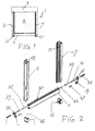
- Figure 1 shows a roller shade like structure 1 for application on the exterior side of building windows.
- shade-like structures are sometimes referred to as vertical awnings, which expression will be used throughout this specification. It should be understood however that such a structure need not be vertical, but can also be arranged in a slanted or even horizontal plane if the necessary adaptations are made to ensure that it can be extended and retracted. Also the arrangement need not be confined to exterior applications alone, but could be similarly effective for indoor mounting
- Figure 1 shows the vertical awning in its extended position with a sheet-like screening material member 3 covering a surface defined by opposite left and right hand guide tracks 5 and 7 and a head box 9.
- the head box 9 accommodates a retraction mechanism such as a roller (not shown, but conventional) to which one edge of the screening material 3 is attached and onto which it can be wound to a retracted position.
- a retraction mechanism such as a roller (not shown, but conventional) to which one edge of the screening material 3 is attached and onto which it can be wound to a retracted position.
- a beam 11 which is movably guided in a vertical direction along the opposite guide tracks 5 and 7.
- a first locking member 13, in the form of a guide track bottom element is positioned at a bottom end of the left hand side track 5 and a second locking member 15 is arranged at a bottom end of the right hand side track 7.
- FIG 2 shows the side guiding tracks 5 and 7, the first and second locking members 13 and 15, as well as the movable beam 11 in an exploded arrangement, so as to show additional elements that would practically be hidden from view in the assembled arrangement of Figure 1.
- Each longitudinal end of beam 11 is provided with an end member to guidingly engage the relevant side track.
- a first end member 17 engages the left hand track 5 and a second end member 19 engages the right hand track 19.
- the first and second end members 17, 19 are attached to the movable beam 11 by means of screws 21 and 23 respectively.
- a boss 25 (27 on the second end member) is made to rotatably fit snugly between front and rear edges of a longitudinal slot 29 and 31 respectively in each of the left and right hand guide tracks 5 and 7 respectively.
- An upper longitudinal edge of beam 11 is provided with a longitudinal groove 33 to receive a free bottom edge of screen member 3 (deleted for clarity from Figure 2).
- first and second plug elements 35, 39 and 37, 41 respectively are forced in from both longitudinal ends of groove 33 to engage a screen rod 43 which will be accommodated in a bottom hem to the screen material (not shown).
- the purpose of the expanding plug elements is to inhibit any possible movements between the screen 3 and the beam 11 when assembled. This arrangement is only given as an example and the skilled person will be aware of alternative solutions to unmoveably arrest the screen material 3 in respect to the beam 11.
- a pin 45 Spaced below the respective boss 25 of first end member 17 is inserted a pin 45 to extend laterally from the first end member.
- a similarly laterally extending pin 47 is correspondingly inserted in the second end member 19.
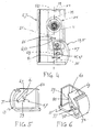
- Figure 3 shows a left hand end portion of beam 11 with the left hand or first end member 17 and screen 3 attached thereto.
- the guide track 5 is only shown in dotted lines, with the first locking member 13 shown in full and immediately below the beam 11, as it would be when the screen 3 is almost fully extended.
- the laterally extending pin 45 is projecting from the end member 17 to extend parallel to boss 25 and well into the interior of the guide track 5.
- the boss 25 has a cylindrical stem portion 49 and a retaining flange 51.
- Retaining flange 51 would prevent the boss 25 to escape from slot 29 in the guide track 5.
- the second end member 19 is preferably made identical to the first end member 17 and a further description will thereby be redundant.
- the cylindrical portion 49 will have a diameter which very closely approaches the lateral dimension of the guiding slot 29 in guide track 5.
- the cylindrical portion 49 preferably also is of such a length to allow the beam 11 to move away to some extent from the guide track 5, to compensate for any inaccuracies in the parallelness of the opposite guide tracks 5 and 7 when installed on a building.
- the flange 51 will limit the length of the cylindrical portion 49 and prevent its escape from the guide track 5 and thereby limit the extent of movement allowed.
- the laterally extending pin 45 is of a substantially smaller diameter than the cylindrical portion 49 so that it may move from a front edge of slot 29 to a rear edge thereof. The fore and after movement of pin 45 will allow the beam 11 to tilt, to a certain extent, around the cylindrical portion 49.
- Figure 4 is a transparent view taken in the length direction of beam 11, with the side guiding tracks 5 and 7 in overlapping arrangement, as seen from outside the left hand guide track 5.
- the reference numerals in Figure 4 will generally refer to the left hand guide channel 5 and its locking member 13, but should be understood to have equivalent relevance to the right hand side guide 7 and locking member 15, which are somewhat hidden in the view of Figure 4, except where stated to be different.
- the slot 29 (and likewise the slot 31 in the other guide track) has a rear edge 52 and a front edge 53, between which the cylindrical portion 49 of boss 25 is vertically slidably and rotatably retained.
- the lower extending pin 45 has a substantially smaller diameter and can be forwardly and rearwardly deflected between the front edge 53 and rear edge 52 of the slot 29
- the beam 11 will normally take a vertical position, aligned with a centre line 55 of slot 29.
- Figure 4 shows the beam 11 in a tilted position, with the extending pin 45 deflected towards the front edge 53 of slot 29.
- first or left hand locking member 13 has a first locking body 57 and the second or right hand locking member 15 has a second locking body 59.
- Each of the first and second locking bodies 57, 59 has an apex 61, 63 formed at an upper end thereof.
- the first and second apexes 61, 63 are each reardwardly spaced from centre line 55 at a distance 65 which is about equal or slightly greater than half of the diameter of the extending pin 45 (and 47). This ensures that with the lowering of beam 11 for the extension of the screen or sheet member 3, both of the extending pins 45 and 47 will be positioned in front of forward sloping surfaces 67 and 69 of the first and second locking bodies 57, 59.
- th pins 45 and 47 Upon further lowering of beam 11, th pins 45 and 47 will reach a forward edge 71 and 73 on each of the relevant left and right hand forward sloping surfaces 67 and 69. Only on the right hand locking member 15 there is a guiding hump 75, which prevents the right hand extending pin 47 from returning to the centre line 55 if lowered below the forward edge 73 of the right hand locking member 15. A rearward sloping surface on hump 75 guides pin 47 into recess 77 at the bottom of the second locking body 59 when movement of beam 11 is reversed from lowering into raising. The entire beam 11 and left hand extending pin 45 will follow this movement and similarly lock into a recess 79 provided on the bottom end of the first locking body 57.
- Each of the locking bodies 57 and 59 may be provided with a sloped rear surface 83 and 85 respectively to guide each of pins 45 and 47 over the apexes 61 and 63 respectively upon retraction of the sheet material 3 and beam 11. From a comparison of Figures 5 and 6 it will further be apparent that the bottom recess 79 of the first locking body 57 is less deep than the bottom recess 77 of the second locking body 59. This is intentional to ensure that no locking of pin 45 shall occur when pin 47 is unlocked from recess 77.
Landscapes
- Engineering & Computer Science (AREA)
- Architecture (AREA)
- Structural Engineering (AREA)
- Civil Engineering (AREA)
- Operating, Guiding And Securing Of Roll- Type Closing Members (AREA)
- Blinds (AREA)
Abstract
Description
- The invention relates to a locking device for locking an extendable and retractable blind, shade or awning in its extended position
- Such blinds, shades or awnings can have a rotatably mounted roller around which a suitable flexible sheet like material, including cloth, fabric, curtain or screen material, is wound.
A free end of such wound sheet like material, opposite the roller, is attached to a movable beam which is movably engaged, at its longitudinal ends, in side guide tracks arranged on opposites lateral sides of the sheet like material. - Such blinds shades or awnings amongst others are known from EP 0305081 or EP 0957230. A particular difficulty with these known arrangements is that the locking devices are symetrically duplicated on the relevant opposite lateral sides of these blinds, shades or awnings and as a consequence have to operate simultaneously.
Especially in outdoor applications it has sometimes been experienced that gusts of wind can interfere with the simultaneous operation of the locking devices on either lateral side. As a result the blinds, shades or awnings have occasionally only locked on one lateral side or even more serious the repetitive sequential operation of the locking mechanism has become disordered. It is an object of the present invention to prevent such possibly inconvenient mishaps. - To this end the invention provides for a locking assembly for releasably holding a movable end bar of an extendable and retractable blind, shade or awning, having such an end bar mounted for translation along opposite lateral guide tracks, wherein the locking assembly includes a first part associated with the lateral guide track at a stationary position thereof and a second part associated with the movable end beam engageable with and disengageable from the first part upon inverting the movement of the beam from a first direction of movement to a second direction of movement, wherein the first part comprises a first locking body at a first of the lateral guide tracks and a second locking body at a second of the lateral guide tracks and wherein the first locking body is different from the second locking body.
- The invention will now be explained in more detail with reference to the accompanying drawing figures in which:
- Figure 1. shows a vertical awning modified to include a locking device in accordance with the invention;
- Figure 2. is an exploded view of only those components of the awning of Figure 1 that are generally associated with the locking device;
- Figure 3, is a partial perspective view of an end portion of a movable beam adjacent its end position for an extended position of the vertical awning.
- Figure 4, is a transparent view of a bottom portion of the side guiding tracks in overlapping position,
- Figure 5, is a perspective view of the left hand guide track bottom element; and
- Figure 6 is a perspective view of the right hand guide track bottom element
-
- Figure 1 shows a roller shade like structure 1 for application on the exterior side of building windows. Such shade-like structures are sometimes referred to as vertical awnings, which expression will be used throughout this specification. It should be understood however that such a structure need not be vertical, but can also be arranged in a slanted or even horizontal plane if the necessary adaptations are made to ensure that it can be extended and retracted. Also the arrangement need not be confined to exterior applications alone, but could be similarly effective for indoor mounting Figure 1 shows the vertical awning in its extended position with a sheet-like
screening material member 3 covering a surface defined by opposite left and righthand guide tracks head box 9. Thehead box 9 accommodates a retraction mechanism such as a roller (not shown, but conventional) to which one edge of thescreening material 3 is attached and onto which it can be wound to a retracted position. To a free end of thescreening material 3 opposite thehead box 9 is attached a beam 11 which is movably guided in a vertical direction along theopposite guide tracks - A
first locking member 13, in the form of a guide track bottom element is positioned at a bottom end of the lefthand side track 5 and asecond locking member 15 is arranged at a bottom end of the righthand side track 7. - Figure 2 shows the
side guiding tracks second locking members first end member 17 engages theleft hand track 5 and asecond end member 19 engages theright hand track 19. The first andsecond end members screws 21 and 23 respectively. As best seen on the first end member 17 a boss 25 (27 on the second end member) is made to rotatably fit snugly between front and rear edges of alongitudinal slot hand guide tracks longitudinal groove 33 to receive a free bottom edge of screen member 3 (deleted for clarity from Figure 2). For the attachment of the screen member in thelongitudinal groove 33 expanding first andsecond plug elements groove 33 to engage ascreen rod 43 which will be accommodated in a bottom hem to the screen material (not shown). - The purpose of the expanding plug elements is to inhibit any possible movements between the
screen 3 and the beam 11 when assembled. This arrangement is only given as an example and the skilled person will be aware of alternative solutions to unmoveably arrest thescreen material 3 in respect to the beam 11. - Spaced below the
respective boss 25 offirst end member 17 is inserted apin 45 to extend laterally from the first end member. A similarly laterally extendingpin 47 is correspondingly inserted in thesecond end member 19. - For a further description of these laterally extending pins45, 47 reference will be had to Figures 3-6 hereinbelow.
- Figure 3 shows a left hand end portion of beam 11 with the left hand or
first end member 17 andscreen 3 attached thereto. For clarity theguide track 5 is only shown in dotted lines, with thefirst locking member 13 shown in full and immediately below the beam 11, as it would be when thescreen 3 is almost fully extended. Also visible in Figure 3 is how the laterally extendingpin 45 is projecting from theend member 17 to extend parallel toboss 25 and well into the interior of theguide track 5. Further shown in Figure 3 is that theboss 25 has acylindrical stem portion 49 and aretaining flange 51. - Retaining
flange 51 would prevent theboss 25 to escape fromslot 29 in theguide track 5. Thesecond end member 19 is preferably made identical to thefirst end member 17 and a further description will thereby be redundant. Thecylindrical portion 49 will have a diameter which very closely approaches the lateral dimension of the guidingslot 29 inguide track 5. Thecylindrical portion 49 preferably also is of such a length to allow the beam 11 to move away to some extent from theguide track 5, to compensate for any inaccuracies in the parallelness of theopposite guide tracks flange 51 will limit the length of thecylindrical portion 49 and prevent its escape from theguide track 5 and thereby limit the extent of movement allowed. It is also seen in Figure 3 that the laterally extendingpin 45 is of a substantially smaller diameter than thecylindrical portion 49 so that it may move from a front edge ofslot 29 to a rear edge thereof. The fore and after movement ofpin 45 will allow the beam 11 to tilt, to a certain extent, around thecylindrical portion 49. - The purpose for this tilting movement will now be explained in reference to Figures 4-6 Figure 4 is a transparent view taken in the length direction of beam 11, with the
side guiding tracks hand guide track 5. The reference numerals in Figure 4 will generally refer to the lefthand guide channel 5 and itslocking member 13, but should be understood to have equivalent relevance to the righthand side guide 7 andlocking member 15, which are somewhat hidden in the view of Figure 4, except where stated to be different. - It is seen that the slot 29 (and likewise the
slot 31 in the other guide track) has arear edge 52 and afront edge 53, between which thecylindrical portion 49 ofboss 25 is vertically slidably and rotatably retained. The lower extendingpin 45 has a substantially smaller diameter and can be forwardly and rearwardly deflected between thefront edge 53 andrear edge 52 of theslot 29 By gravity and by inherent resiliency in thesheet member 3, the beam 11 will normally take a vertical position, aligned with acentre line 55 ofslot 29. Figure 4 shows the beam 11 in a tilted position, with the extendingpin 45 deflected towards thefront edge 53 ofslot 29. In conjunction with Figures 5 and 6 it is seen that the first or lefthand locking member 13 has afirst locking body 57 and the second or righthand locking member 15 has asecond locking body 59. Each of the first andsecond locking bodies apex 61, 63 formed at an upper end thereof. The first andsecond apexes 61, 63 are each reardwardly spaced fromcentre line 55 at adistance 65 which is about equal or slightly greater than half of the diameter of the extending pin 45 (and 47). This ensures that with the lowering of beam 11 for the extension of the screen orsheet member 3, both of the extendingpins forward sloping surfaces 67 and 69 of the first andsecond locking bodies th pins forward edge surfaces 67 and 69. Only on the righthand locking member 15 there is a guidinghump 75, which prevents the righthand extending pin 47 from returning to thecentre line 55 if lowered below theforward edge 73 of the righthand locking member 15. A rearward sloping surface onhump 75guides pin 47 into recess 77 at the bottom of thesecond locking body 59 when movement of beam 11 is reversed from lowering into raising. The entire beam 11 and lefthand extending pin 45 will follow this movement and similarly lock into arecess 79 provided on the bottom end of thefirst locking body 57. The reversed movement of beam 11 can be obtained in the manner described in European patent publication: EP 0 957 230, to which reference is made for further clarification. Alternatively on an electrically operated awning or shade, such reverse movement for locking beam 11 may also be obtained by electrical commands which alter the direction of rotation of an electric motor. - Such arrangements are considered well within the common knowledge of the skilled person and a detailed description will thereby be redundant. A further reversal of movement, i.e. lowering of beam 11 while locked into the
recesses 77 and 79, will allow thepin centre line 55. This is so because, as seen in Figure 4, the location of therecesses 77 and 79 holdingpins distance 81 forwardly of thecentre line 55. By gravity of the beam 11, aided by inherent resiliency in thesheet member 3, thepins centre line 55. This may be different in situations where the side guides 5 and 7 are not vertical, in which case additional provisions may be required to bias thepins centre line 55. All such modifications are regarded to be within the purview of the skilled person and within the scope of the present invention. Each of the lockingbodies rear surface pins apexes 61 and 63 respectively upon retraction of thesheet material 3 and beam 11. From a comparison of Figures 5 and 6 it will further be apparent that thebottom recess 79 of thefirst locking body 57 is less deep than the bottom recess 77 of thesecond locking body 59. This is intentional to ensure that no locking ofpin 45 shall occur whenpin 47 is unlocked from recess 77. By this arrangement of differing lockingbodies hump 75, are only provided on the right hand one of the lockingmember 15 and are eliminated from the lefthand locking member 13. - It is thus believed that the operation and construction of the present invention will be apparent from the foregoing description. The term comprising when used in this description or the appended claims should not be construed in an exclusive or exhaustive sense but rather in an inclusive sense. Features which are not specifically or explicitely described or claimed may be additionally included in the structure according to the present invention without deviating from its scope.
- The invention is further not limited to any embodiment herein described and, within the purview of the skilled person, modifications are possible which should be considered within the scope of the appended claims. Equally all kinematic inversions are to be considered within the scope of the present invention.
- Reference to either axially, radially or tangentially if used in the above is generally in relation to rotatable or cylindrical bodies of elements described.
- Where in the above reference is made to longitudinal or lateral this is in reference to the length or width directions respectively of elements which have an oblong appearance in the accompanying drawings. This interpretation however has only been used for ease of reference and should not be construed as a limitation of the shape of such elements.
- Expressions, such as right, left, horizontal, vertical, above, below, upper, lower, top, bottom or the like if used in reference to the construction as illustrated in the accompanying drawings are relevant to the relative positions and in a different orientation of the construction should be interpreted in accordance with comparable relative positions.
Claims (1)
- A locking assembly for releasably holding a movable end bar (11) of an extendable and retractable blind, shade or awning (1), having such an end bar (11) mounted for translation along opposite lateral guide tracks (5, 7), wherein the locking assembly includes a first part (13, 15) associated with the lateral guide track (5, 7) at a stationary position thereof and a second part (45, 47) associated with the movable end beam (11) engageable with and disengageable from the first part (13, 15) upon inverting the movement of the beam (11) from a first direction of movement to a second direction of movement, wherein the first part (13, 15) comprises a first locking body (57) at a first of the lateral guide tracks (15) and a second locking body (59) at a second of the lateral guide tracks (7) and wherein the first locking body (57) is different from the second locking body (59)
Priority Applications (1)
| Application Number | Priority Date | Filing Date | Title |
|---|---|---|---|
| EP03250269A EP1331353A3 (en) | 2002-01-16 | 2003-01-16 | Locking device for an extendable and retractable blind or shade |
Applications Claiming Priority (3)
| Application Number | Priority Date | Filing Date | Title |
|---|---|---|---|
| EP02075172 | 2002-01-16 | ||
| EP02075172 | 2002-01-16 | ||
| EP03250269A EP1331353A3 (en) | 2002-01-16 | 2003-01-16 | Locking device for an extendable and retractable blind or shade |
Publications (2)
| Publication Number | Publication Date |
|---|---|
| EP1331353A2 true EP1331353A2 (en) | 2003-07-30 |
| EP1331353A3 EP1331353A3 (en) | 2004-01-07 |
Family
ID=26077589
Family Applications (1)
| Application Number | Title | Priority Date | Filing Date |
|---|---|---|---|
| EP03250269A Withdrawn EP1331353A3 (en) | 2002-01-16 | 2003-01-16 | Locking device for an extendable and retractable blind or shade |
Country Status (1)
| Country | Link |
|---|---|
| EP (1) | EP1331353A3 (en) |
Cited By (4)
| Publication number | Priority date | Publication date | Assignee | Title |
|---|---|---|---|---|
| EP1571291A1 (en) * | 2004-03-03 | 2005-09-07 | BVBA Vervaeke | Roller gate |
| WO2007133450A2 (en) * | 2006-05-12 | 2007-11-22 | Wayne-Dalton Corp. | Assembly to lock a storm curtain adjacent to an opening in a building |
| FR2901570A1 (en) * | 2006-05-29 | 2007-11-30 | Aluroy Sa | Heel for slide of roller blind, has U-shaped projecting portions projecting with respect to base and supported against inner surfaces of lateral and transversal walls of section, when base closes lower opening of section |
| ITMO20130226A1 (en) * | 2013-08-02 | 2015-02-03 | Fra Ma S P A | DROP-UP TENT WITH IMPROVED TENSION IN MAXIMUM EXTENSION POSITION |
Citations (1)
| Publication number | Priority date | Publication date | Assignee | Title |
|---|---|---|---|---|
| EP0579335A1 (en) * | 1992-07-13 | 1994-01-19 | Hamstra-Weesp B.V. | Rollable gauze screen |
-
2003
- 2003-01-16 EP EP03250269A patent/EP1331353A3/en not_active Withdrawn
Patent Citations (1)
| Publication number | Priority date | Publication date | Assignee | Title |
|---|---|---|---|---|
| EP0579335A1 (en) * | 1992-07-13 | 1994-01-19 | Hamstra-Weesp B.V. | Rollable gauze screen |
Cited By (8)
| Publication number | Priority date | Publication date | Assignee | Title |
|---|---|---|---|---|
| EP1571291A1 (en) * | 2004-03-03 | 2005-09-07 | BVBA Vervaeke | Roller gate |
| BE1015924A3 (en) * | 2004-03-03 | 2005-11-08 | Bvba Vervaeke | Oprolpoort. |
| WO2007133450A2 (en) * | 2006-05-12 | 2007-11-22 | Wayne-Dalton Corp. | Assembly to lock a storm curtain adjacent to an opening in a building |
| WO2007133445A2 (en) * | 2006-05-12 | 2007-11-22 | Wayne-Dalton Corp. | Assembly to lock a storm curtain adjacent to an opening in a building |
| WO2007133445A3 (en) * | 2006-05-12 | 2008-01-17 | Wayne Dalton Corp | Assembly to lock a storm curtain adjacent to an opening in a building |
| WO2007133450A3 (en) * | 2006-05-12 | 2008-10-30 | Wayne Dalton Corp | Assembly to lock a storm curtain adjacent to an opening in a building |
| FR2901570A1 (en) * | 2006-05-29 | 2007-11-30 | Aluroy Sa | Heel for slide of roller blind, has U-shaped projecting portions projecting with respect to base and supported against inner surfaces of lateral and transversal walls of section, when base closes lower opening of section |
| ITMO20130226A1 (en) * | 2013-08-02 | 2015-02-03 | Fra Ma S P A | DROP-UP TENT WITH IMPROVED TENSION IN MAXIMUM EXTENSION POSITION |
Also Published As
| Publication number | Publication date |
|---|---|
| EP1331353A3 (en) | 2004-01-07 |
Similar Documents
| Publication | Publication Date | Title |
|---|---|---|
| US6047762A (en) | Shade control for a vehicle window | |
| US9347261B2 (en) | Adjustment mechanisms for shades | |
| US10329836B2 (en) | Window covering positional adjustment apparatus | |
| US4294302A (en) | Shutter and awning device | |
| US6062147A (en) | Roller assembly, table assembly, and modesty screen | |
| CA2115616C (en) | Corner assembly and frame comprising such assembly | |
| US8656978B2 (en) | Roller screen assemblies | |
| JP2005511928A (en) | Slide screen edge seal | |
| US20170362887A1 (en) | Slat control mechanism for blinds | |
| US7628195B2 (en) | Nonretractable covering for architectural openings | |
| US6061961A (en) | Swinging security door | |
| EP1331353A2 (en) | Locking device for an extendable and retractable blind or shade | |
| TWI648460B (en) | Window shade and its spring drive system | |
| EP2307652B1 (en) | Screening device with a locking mechanism for a tilt device | |
| CA3006656A1 (en) | Covering for an architectural feature having a bottom rail leveling mechanism | |
| US20040221969A1 (en) | Combination window covering | |
| JP4075232B2 (en) | Shutter locking / unlocking device | |
| AU2006200242B2 (en) | Retractable Screen | |
| EP1270865B1 (en) | Sunblind | |
| JP5058502B2 (en) | Locking device for switchgear | |
| JP4010072B2 (en) | Detection device position adjustment mechanism | |
| JP4397231B2 (en) | Sunroof device | |
| JPH02212220A (en) | Motor-driven slide type sunvisor | |
| JPH0422710Y2 (en) | ||
| JPH05263573A (en) | Horizontal type blind |
Legal Events
| Date | Code | Title | Description |
|---|---|---|---|
| PUAI | Public reference made under article 153(3) epc to a published international application that has entered the european phase |
Free format text: ORIGINAL CODE: 0009012 |
|
| AK | Designated contracting states |
Designated state(s): AT BE BG CH CY CZ DE DK EE ES FI FR GB GR HU IE IT LI LU MC NL PT SE SI SK TR |
|
| AX | Request for extension of the european patent |
Extension state: AL LT LV MK RO |
|
| PUAL | Search report despatched |
Free format text: ORIGINAL CODE: 0009013 |
|
| AK | Designated contracting states |
Kind code of ref document: A3 Designated state(s): AT BE BG CH CY CZ DE DK EE ES FI FR GB GR HU IE IT LI LU MC NL PT SE SI SK TR |
|
| AX | Request for extension of the european patent |
Extension state: AL LT LV MK RO |
|
| AKX | Designation fees paid | ||
| REG | Reference to a national code |
Ref country code: DE Ref legal event code: 8566 |
|
| STAA | Information on the status of an ep patent application or granted ep patent |
Free format text: STATUS: THE APPLICATION IS DEEMED TO BE WITHDRAWN |
|
| 18D | Application deemed to be withdrawn |
Effective date: 20040708 |