EP1329886A2 - Disk apparatus - Google Patents
Disk apparatus Download PDFInfo
- Publication number
- EP1329886A2 EP1329886A2 EP02258725A EP02258725A EP1329886A2 EP 1329886 A2 EP1329886 A2 EP 1329886A2 EP 02258725 A EP02258725 A EP 02258725A EP 02258725 A EP02258725 A EP 02258725A EP 1329886 A2 EP1329886 A2 EP 1329886A2
- Authority
- EP
- European Patent Office
- Prior art keywords
- disk
- transfer
- transfer mechanism
- diameter
- detectors
- Prior art date
- Legal status (The legal status is an assumption and is not a legal conclusion. Google has not performed a legal analysis and makes no representation as to the accuracy of the status listed.)
- Granted
Links
Images





Classifications
-
- G—PHYSICS
- G11—INFORMATION STORAGE
- G11B—INFORMATION STORAGE BASED ON RELATIVE MOVEMENT BETWEEN RECORD CARRIER AND TRANSDUCER
- G11B17/00—Guiding record carriers not specifically of filamentary or web form, or of supports therefor
- G11B17/22—Guiding record carriers not specifically of filamentary or web form, or of supports therefor from random access magazine of disc records
- G11B17/225—Guiding record carriers not specifically of filamentary or web form, or of supports therefor from random access magazine of disc records wherein the disks are transferred from a fixed magazine to a fixed playing unit using a moving carriage
-
- G—PHYSICS
- G11—INFORMATION STORAGE
- G11B—INFORMATION STORAGE BASED ON RELATIVE MOVEMENT BETWEEN RECORD CARRIER AND TRANSDUCER
- G11B17/00—Guiding record carriers not specifically of filamentary or web form, or of supports therefor
- G11B17/02—Details
- G11B17/021—Selecting or spacing of record carriers for introducing the heads
-
- G—PHYSICS
- G11—INFORMATION STORAGE
- G11B—INFORMATION STORAGE BASED ON RELATIVE MOVEMENT BETWEEN RECORD CARRIER AND TRANSDUCER
- G11B17/00—Guiding record carriers not specifically of filamentary or web form, or of supports therefor
- G11B17/02—Details
- G11B17/04—Feeding or guiding single record carrier to or from transducer unit
- G11B17/05—Feeding or guiding single record carrier to or from transducer unit specially adapted for discs not contained within cartridges
- G11B17/051—Direct insertion, i.e. without external loading means
-
- G—PHYSICS
- G11—INFORMATION STORAGE
- G11B—INFORMATION STORAGE BASED ON RELATIVE MOVEMENT BETWEEN RECORD CARRIER AND TRANSDUCER
- G11B17/00—Guiding record carriers not specifically of filamentary or web form, or of supports therefor
- G11B17/02—Details
- G11B17/04—Feeding or guiding single record carrier to or from transducer unit
- G11B17/0401—Details
- G11B17/0402—Servo control
- G11B17/0404—Servo control with parallel drive rollers
Definitions
- the present invention relates to a disk apparatus in which a disk is transferred to a rotating section by a transfer mechanism, and more particularly, to a disk apparatus in which a disk can be reliably clamped in a rotating section.
- Car-mounted disk. apparatus and the like adopt so-called slot-in loading in which, when a disk inserted from a loading slot of the apparatus is pulled into the apparatus and transferred to a rotating section by a transfer mechanism.
- the stopper In a disk apparatus in which both a large-diameter disk having a diameter of 12 cm and a small-diameter disk having a diameter of 8 cm can be loaded, the stopper must be selectively moved to a position to position the small-diameter disk relative to the driving section and a position to position the large-diameter relative to the driving section. This also complicates the inner structure of the apparatus.
- a disk inserted from a loading slot passes through a rotating section and is stored in a stock section provided behind the rotating section.
- a stopper for positioning the disk relative to the rotating section is provided in such a disk apparatus, it is placed on the transfer path for the disk, and therefore, a mechanism for causing the stopper to recede from the transfer path is needed.
- a further type of disk apparatus is possible in which an optical sensor or a mechanical switch for detecting that the center hole of a carried disk is aligned with the center of rotation of a rotating section is provided without using the stopper, and in which a transfer mechanism is stopped in response to the operation of the optical sensor or the mechanical switch.
- the optical sensor when used, the cost of the apparatus is increased, and incorrect operation may be caused by a transparent portion of the disk or external light.
- the diameter varies among disks, it is considerably difficult for the optical sensor or the mechanical switch to precisely detect that the center hole of the disk is aligned with the rotating section.
- the present invention has been made to overcome the above problems, and an object of the present invention is to provide a disk apparatus in which a disk can be reliably placed in such a position as to be clamped in a rotating section, without providing a mechanical stopper on a transfer path of the disk.
- the present invention provides a disk apparatus including a guide member extending in a disk transfer direction so as to guide a disk to be transferred, a transfer mechanism for applying a transfer force to the disk, a rotating section to be fitted in a center hole of the disk transferred by the transfer mechanism so as to apply a rotating force to the disk, a clamp mechanism for fitting the rotating section in the center hole of the disk, and a control section for controlling operation of said disk apparatus.
- the guide member has a pair of detectors arranged in the disk transfer direction with a predetermined distance therebetween so as to be brought into a detection state by a peripheral edge of the disk when the disk reaches such a position as to be clamped by the rotating section.
- the control section operates the clamp mechanism so that the rotating section is urged toward the disk when one of the detectors is brought into a detection state during the transfer of the disk, determines that a clamping operation of the disk is completed when both of the detectors are in a detection state and the detection state continues for a predetermined time, and stops the transfer mechanism in response to the determination.
- control section reverses the transfer direction of the transfer mechanism at least once after it recognizes that both the detectors are actuated, and determines that the clamping operation of the disk is completed when the detectors are continuously actuated for a predetermined time.
- a retry for reversing the transfer direction of the transfer mechanism at least once is performed when one of the detectors is brought into a detection state during the transfer of the disk and both the detectors are not actuated within a predetermined time after the rotating section is urged toward the disk.
- the transfer mechanism may transfer a disk loaded from a loading slot toward the rotating section, or may transfer a disk, which is selected from a plurality of disks stored in a stock section provided in the disk apparatus, toward the rotating section.
- the center hole of the disk can be reliably clamped on the rotating section. Furthermore, since two detection switches are used, the rotating section can be pressed against the disk when the center hole of the disk moves close to the rotating section, and it can be precisely detected later whether or not the center hole is fitted on the rotating section.
- a stopper for positioning the disk relative to the rotating section is unnecessary, unlike before, and a mechanism for causing the stopper to recede is also unnecessary. Even when the loading slot, the transfer mechanism, the rotating section, and the stock section are arranged in order in the disk apparatus, a disk loaded from the loading slot and a disk drawn from the stock section can be reliably clamped on the rotating section.
- FIG. 1 is a perspective view showing an example of an inner structure of a disk apparatus according to the present invention
- FIG. 2 is a plan view of the disk apparatus
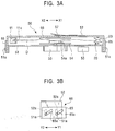
- FIG. 3A is a cross-sectional view of a driving unit, taken along line III-III in FIG. 2
- FIG. 3B is a side view of the driving unit
- FIG. 11 is a front view of the disk apparatus.
- a disk apparatus 1 shown in FIGS. 1 and 2 is capable of playback and/or recording of small-diameter disks having a diameter of 8 cm and large-diameter disks having a diameter of 12 cm, such as CDs (compact disks) or DVDs (digital versatile disks).
- a plurality of disks of 12 cm in diameter can be stored inside the disk apparatus 1, and one of the disks is selected for driving.
- a nose section 80 having a liquid crystal display panel 81 and various switches 82 is provided on the front side (Y2-side) of the main body of the disk apparatus 1.
- the nose section 80 also has a loading slot 83 extending in the widthwise direction (X1-X2 direction).
- a stock section 3 in which a plurality of large-diameter disks can be stacked in the height direction (Z-direction) is disposed on the back side (Y1-side) of the disk apparatus 1.
- the disks are held in disk holders 41 of the stock section 3, respectively, and are stored while being stacked in the height direction.
- a disk transfer section 5 is disposed on the Y2-side of the disk apparatus 1 between the loading slot 83 of the nose section 80 and the stock section 3 so as to carry a disk D into and out of the disk apparatus 1.
- a first moving member 6 and a second moving member 7 are disposed on a base 2 so that they are movable in the widthwise direction (X1-X2 direction).
- the first moving member 6 has a rack 6a
- the second moving member 7 has a rack opposing the rack 6a.
- a connecting gear 8 is disposed as a distance setting section on the base 2, and is rotationally driven by a setting motor M shown in FIG. 2.
- the connecting gear 8 is meshed with both the rack 6a of the first moving member 6 and the rack of the second moving member 7.
- the second moving member 7 is provided with a guide member 11 that extends in the Y1-Y2 direction serving as the loading and ejecting direction of the disk D.
- a guide groove 11a extending in the Y-direction is formed on the X1-side face of the guide member 11. As shown in FIG. 3A, the cross section of the guide groove 11a is shaped like the letter V that opens wide on the X1 side and is narrow on the X2 side.
- a detection arm 12 is provided at an ejection-side (Y2-side) end of the guide member 11.
- the detection arm 12 is supported so that it can turn about a shaft 13 clockwise and counterclockwise in FIG. 2, and is urged counterclockwise by an urging member (not shown).
- the detection arm 12 has a detection piece 12a bent at the ejection-side end of the guide member 11.
- the detection piece 12a When the detection piece 12a is pushed outward (in the X2-direction) by the peripheral edge of a disk D inserted in the guide groove 11a of the guide member 11, the detection arm 12 turns clockwise.
- a pressing piece 12b bent below the plane of the figure is formed at the other end of the detection arm 12, and opposes an actuator of a detection switch 14.
- the detection switch 14 is turned on by the pressing piece 12b.
- the pressing piece 12b separates from the actuator of the detection switch 14, thereby turning the detection switch 14 off.
- a transfer mechanism 20 including first to fourth transfer rollers 21, 22, 23, and 24 that are arranged in the loading and ejecting direction (Y-direction) of the disk D is provided on the surface of the first moving member 1 so as to face the guide member 11.
- each of the first to fourth transfer rollers 21, 22, 23, and 24 have flanges whose thickness gradually decreases from the center toward the outer peripheral side, and the edge of the disk D is held in a V-groove formed between the flanges.
- a carrier motor M1 is provided in the disk apparatus 1.
- the power of the carrier motor M1 is reduced in speed by a reduction gear train, and is transmitted to the transfer rollers 21, 22, 23, and 24 through transmission gears 25, 26, and 27 and the like, thereby rotating the first to fourth transfer rollers 21, 22, 23, and 24 in the same direction.
- the disk D is carried into the inner portion of the apparatus (in the Y1-direction).
- the disk D is carried outward (in the Y2-direction).
- the first moving means 6 is provided with a pivot arm 28 that can pivot on a support shaft within a predetermined angular range, and the first transfer roller 21 is supported at the leading end of the pivot arm 28.
- the pivot arm 28 is constantly urged clockwise by an urging member such as a tension coil spring.
- a detection switch 29 is provided on the first moving member 6 so that it is turned on when the pivot arm 28 pivots counterclockwise by a predetermined angle.
- the detection switch 14 and the detection switch 29 constitute a loading detector that detects the loading and ejection of the disk into and out of the disk apparatus 1.
- a linear position sensor is disposed on the base 2 so as to detect the X-direction moving position of the second moving member 7.
- the linear position sensor is, for example, a linear variable resistor, and can detect the position of the second moving member 7 on the basis of the resistance that linearly changes, and as a result, can detect the opposing distance Wx between the guide member 11 and the transfer mechanism 20.
- the guide member 11 has a first detection switch 31 and a second detection switch 32.
- the first detection switch 31 and the second detection switch 32 function as a pair of detectors that detect the movement of the disk D to a position where it can be clamped.
- FIG. 5 is a cross-sectional view of a portion of the guide member 11 in which the first or second detection switch 31 or 32 is provided.
- an actuator 31a or 32a of the first detection switch 31 or the second detection switch 32 projects in the guide groove 11a of the guide member 11.
- the actuator 31a or 32a is pressed by the peripheral edge of the disk that is moving in the guide groove 11a, the first detection switch 31 or the second detection switch 32 is turned on (detection state).
- the stock section 3 has a plurality of (six in FIG. 1) disk holders 41 vertically stacked in the thickness direction of a large-diameter disk D having a diameter of 12 cm, and each of the disk holders 41 holds the front edge of a large-diameter disk D that is carried therein while being clamped by the guide member 11 and the transfer mechanism 20.
- a plurality of guide columns 42 vertically stand on the base 2, and are rotatably supported. Pinions 43 are fixed to the base ends of all the guide columns 42, respectively, and a ring-shaped gear 44 is disposed on the base 2 so as to be meshed with the pinions 43. When the ring-shaped gear 44 is driven by a selection motor (not shown), all the guide columns 42 are rotated synchronously.
- a screw groove 42a is formed on the outer periphery of every guide column 42.
- the pitch of the screw groove 42a is small in the upper and lower portions of the guide column 42, and is large in the center portion.
- a plurality of circular insertion holes are formed in the disk holders 41, and a projection is formed on the inner surface of each insertion hole so as to be meshed with the screw groove 42a of the guide column 42.
- the disk holders 41 are stored so that they are tightly stacked in the upper and lower portions. Since the pitch of the screw grooves 42a is large in the center potions of the guide columns 42, the disk holders 41 can vertically move apart from the disk holders 41 vertically adjacent thereto. With the vertical movement of the disk holders 41, any of the disk holders 41 is selected. As shown in FIG. 1. a selected disk holder 41A stops at the same height as the guide member 11 and the transfer mechanism 20.
- a plurality of disk holders 41, and a driving section composed of by the guide columns 42, the pinions 43, the ring-shaped gear 44, and the selection motor (not shown) so as to vertically drive the disk holders 41 constitute a disk selecting section.
- a driving unit 50 is provided on the base 2. As shown in FIG. 3A, the driving unit 50 includes a driving chassis 51 and a clamp chassis 52. The driving chassis 51 and the clamp chassis 52 are combined in parallel with each other so as to move closer to and further apart from each other. The driving chassis 51 is placed below the transfer path of the disk D defined by the guide member 11 and the transfer mechanism 20, and the clamp chassis 52 is placed above the transfer path.
- the driving chassis 51 has a spindle motor 53 on the lower side, and a turntable 54 to be rotated by the spindle motor 53 on the upper side.
- the turntable 54 serves as the rotating section for rotating a disk D.
- An optical head 55 is provided below the driving chassis 51.
- the optical head 55 applies laser light for playback or recording to the disk D through a cutout formed in the driving chassis 51, and moves along the recording surface of the disk D.
- a clamper 56 is rotatably supported by the clamp chassis 52, and is urged downward by a leaf spring 57.
- a clamp mechanism 66 is provided on the driving chassis 51 or the clamp chassis 52 of the driving unit 50, or on the base 2, and the driving chassis 51 and the clamp chassis 52 are vertically moved by the clamp mechanism 66.
- the distance between the driving chassis 51 and the clamp chassis 52 is long, a space is formed between the turntable 54 and the clamper 56 in which the disk D is movable.
- the clamper 56 clamps the disk D between the clamper 56 and the turntable 54 by the force of the leaf spring 57.
- FIG. 3B shows an example of a structure of the clamp mechanism 66.
- Sliding members 65 that can reciprocally move within a predetermined range in the Y1-Y2 direction are placed on both sides of the clamp chassis 52, respectively.
- Pins 51a that protrude from each side face of the driving chassis 51 through slots 52a of the clamp chassis 52 are passed through a pair of inclined cam grooves 65a formed in each of the sliding members 65, respectively.
- the driving chassis 51 is moved down because of the inclined cam grooves 65a when the sliding members 51 move in the Y1-direction, and is moved up when the sliding members 65 move in the Y2-direction.
- the sliding members 65 are moved in the Y1-Y2 direction by the driving force of a motor provided on a moving base (not shown) that supports the driving unit 50 movably in the Y1-Y2 direction.
- FIG. 2 shows a state in which the driving unit 50 has been moved to a driving position.
- a disk D is clamped and rotated by the driving unit 50 that stops at the driving position shown in FIG. 2.
- the driving unit 50 recedes toward the loading side (Y2-side) so that it does not touch disks moving up and down along with the disk holders 41.
- the setting motor M for moving the first moving member 6 and the second moving member 7 so as to set the opposing distance Wx therebetween is driven by a motor driver 63, and the carrier motor M1 for rotating the transfer rollers 21, 22, 23, and 24 is driven by a motor driver 64.
- the motor drivers 63 and 64 are controlled by a main control unit (control section) 61 such as a CPU.
- the above-described motor for driving the clamp mechanism 66 is also driven by the main control unit 61.
- Detection output from the linear position sensor that detects the moving position of the second moving member 7 is applied to the main control unit 61.
- Detection outputs from the detection switches 14 and 29 and detection outputs from the first detection switch 31 and the second detection switch 32 in the guide member 11 are also applied to the main control unit 61.
- a memory 62 such as a RAM, is connected to the main control unit 61.
- the memory 62 stores information, for example, which disk holder 41 of the disk holders 41 holds the disk D.
- the connecting gear 8 when the connecting gear 8 is driven by the setting motor M, the first moving member 6 and the second moving member 7 synchronously move in the X-direction, and as a result, the opposing distance Wx between the guide member 11 and the transfer mechanism 20 is determined.
- the opposing distance Wx between the guide member 11 and the transfer mechanism 20 is set to be smaller than the diameter (8 cm) of a small-diameter disk.
- the transfer rollers 21, 22, 23, and 24 of the transfer mechanism 20 are started in the direction to carry the disk in.
- the main control unit 61 determines that the disk is loaded.
- the setting motor M When it is determined that the disk is loaded, the setting motor M is driven, the first moving member 6 and the second moving member 7 move further apart from each other so as to increase the distance therebetween so that the opposing distance Wx between the guide member 11 and the transfer mechanism 20 allows a small-diameter disk having a diameter of 8 cm to be clamped and transferred.
- the setting of the opposing distance Wx is controlled by detecting the moving position of the second moving member 7 with the linear position sensor.
- the opposing distance Wx is set so that one of the detection arm 12 and the pivot arm 28 is pushed outward and so that only one of the lading-detecting switches 14 and 29 is turned on. Therefore, the main control unit 61 determines that the loaded disk is a small-diameter disk unless both the loading-detecting switches 14 and 29 are simultaneously turned on, and the opposing distance Wx between the guide member 11 and the transfer mechanism 20 is fixed so that the small disk can be clamped and transferred.
- the small-diameter disk is carried into the disk apparatus 1 by the clockwise rotating force of the transfer rollers 21, 22, 23, and 24 of the transfer mechanism 20.
- the disk rolls in the Yl-direction along the guide groove 11a of the guide member 11.
- the small-diameter disk When the small-diameter disk is loaded, it is not carried to the position at which it is held by the disk holder 41 of the stock section 3, but is carried to the position at which it can be driven by the driving unit 50 at the driving position, as shown by a one-dot chain line in FIG. 2.
- the main control unit 61 By monitoring the operating states of the first detection switch 31 and the second detection switch 32 by the main control unit 61, it is detected that the small-diameter disk is transferred to the position of driving by the driving unit 50.
- FIG. 6 shows the relationship among a small-diameter disk Ds having a diameter of 8 cm, the first detection switch 31, and the second detection switch 32.
- the actuator 31a of the first detection switch 31 and the actuator 32a of the second detection switch 32 are arranged in the disk transfer direction with a distance L therebetween.
- the distance L is determined so that the actuators 31a and 32a are simultaneously pressed by the peripheral edge of the small-diameter disk Ds when a center hole D2 of the small-diameter disk Ds is aligned with the center of rotation of the turntable 54, in plan view (as viewed from above).
- the main control unit 61 determines that the center of the small-diameter disk Ds is aligned with the center of rotation of the turntable 54, that is, that the small-diameter disk Ds is placed in such a position as to be clamped on the turntable 54, thereby executing control to stop the driving of the transfer mechanism 20.
- the small-diameter disk Ds is clamped between the turntable 54 and the clamper 56, and is rotated by the driving force of the spindle motor 53.
- Information recorded on the small-diameter disk Ds is reproduced or information is recorded on the small-diameter disk Ds by the optical head 55.
- the small-diameter disk Ds is transferred in the Y2-direction toward the loading slot 83 of the nose section 80 by the guide member 11 and the transfer mechanism 20.
- the operation states of the loading-detecting switches 14 and 29 are monitored by the main control unit 61.
- the transfer rollers 21, 22, 23, and 24 are stopped, and the small-diameter disk Ds is stopped in a state in which a part thereof protrudes from the loading slot 83.
- the opposing distance Wx between the guide member 11 and the transfer mechanism 20 is set to be smaller than when a small-diameter disk Ds is carried.
- the setting motor M starts to increase the distance between the first moving member 6 and the second moving member 7.
- the opposing distance Wx is set so as to allow a small-diameter disk Ds having a diameter of 8 cm to be carried.
- the main control unit 61 determines that the large-diameter disk D is loaded. That is, the two loading-detecting switches 14 and 29 that constitute the loading-detection section also function as a disk-diameter distinguishing section for distinguishing whether the loaded disk is a large-diameter disk D or a small-diameter disk Ds.
- the setting motor M starts again, the first moving member 6 and the second moving member 7 move further apart from each other, and the opposing distance Wx between the guide member 11 and the transfer mechanism 20 is set so that the large-diameter disk D can be clamped and a transfer force can be applied thereto.
- the opposing distance Wx is set by monitoring the output from the linear position sensor by the main control unit 61. Then, the large-diameter disk D is carried in the Y1-direction by the rotating force of the transfer rollers 21, 22, 23, and 24 of the transfer mechanism 20.
- the distance L between the actuators 31a and 32a of the first and second detection switches 31 and 32 is set so that both the first and second detection switches 31 and 32 are brought into an ON state (detection state) when the center of a center hole D1 of the large-diameter disk D having a diameter of 12 cm is aligned with the center of rotation of the turntable 54, in plan view (as viewed from above). That is, the distance L is set so that both the first and second detection switches 31 and 32 are brought into a detection state when a disk is transferred to such a position as to be clamped on the turntable 54, no matter whether the disk is a small-diameter disk Ds of a large-diameter disk D.
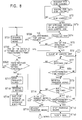
- an operation of clamping the large-diameter disk D on the turntable 54 and an operation of detecting the completion of the clamping operation are controlled according to a flow shown in FIG. 8.
- the large-diameter disk D is clamped on the turntable 54, the spindle motor 53 starts to rotate the disk D, and playback or recording operation is performed by the optical head 55.
- the first moving member 6 and the second moving member 7 are moved further apart from each other to increase the opposing distance Wx between the guide member 11 and the transfer mechanism 20, and the guide member 11 and the transfer mechanism 20 are separated from the peripheral edge of the large-diameter disk D.
- the guide member 11 and the transfer mechanism 20 are similarly separated from the peripheral edge of the disk Ds.
- the spindle motor 53 is rotated for a short period. Since the center hole D1 of the disk D is thereby properly fitted on a positioning projection 54a of the turntable 54, the disk clamping operation can be completed reliably. This makes it possible to precisely set the height of the recording surface of the disk D and to perform a subsequent correcting operation of adjusting the height of an objective lens in the optical head 55 so as to set the distance between the objective lens and the recording surface of the disk D.
- the large-diameter disk D may be ejected from the loading slot 83, or may be transferred into the stock section 3 so as to be held in any disk holder 41.
- the setting motor M starts, the first moving member 6 and the second moving member 7 are moved closer to each other, the opposing distance Wx between the guide member 11 and the transfer mechanism 20 is decreased, and the large-diameter disk D is held between the guide member 11 and the transfer mechanism 20.
- the driving chassis 51 of the driving unit 50 is moved down so as to release the clamping of the disk D by the turntable 54 and the clamper 56.
- the transfer rollers 21, 22, 23, and 24 are driven counterclockwise, and the disk D is carried toward the loading slot 83.
- one of the loading-detecting switches 14 and 29 is turned on and is then turned off, it is determined that the large-diameter disk D reaches the ejecting position, and the transfer rollers 21, 22, 23, and 24 are stopped. Consequently, the large-diameter disk D is stopped with a part thereof protruding from the loading slot 83.
- the opposing distance Wx between the guide member 11 and the transfer mechanism 20 is decreased, and the large-diameter disk D is held between the guide member 11 and the transfer mechanism 20.
- the transfer mechanism 20 is driven in the loading direction so that the large-diameter disk D is transferred into a disk holder 41 disposed at a selecting position 41A, which is placed at the same height as the guide member 11 and the transfer mechanism 20, and is held therein.
- first moving member 6 and the second moving member 7 move further apart from each other to increase the opposing distance Wx between the guide member 11 and the transfer mechanism 20, and the guide member 11 and the transfer mechanism 20 are moved to the positions at which they do not touch the disk D held in the disk holder 41.
- the disk holder 41 By operating a disk selector switch 70 in the nose section 80 corresponding to the number of a selected disk holder 41 in the stock section 3, the disk holder 41 is moved to the selecting position 41A.
- the driving unit 50 recedes toward the loading side (Y2-side) so as not to touch the disk D held in the disk holder 41. Then, the guide columns 42 of the stock section 3 are driven to vertically move the disk holders 41 because of the screw grooves 42a, and are stopped when the selected disk holder 41 reaches the selecting position 41A. When the disk holder 41 at the selecting position 41A is empty, the disk D is carried into the disk holder 41 by the above-described disk loading operation.
- the disk holder 41 In order to select and drive a disk from the stock section 3, by operating a disk selector switch 70 corresponding to the number of a desired disk holder 41, the disk holder 41 is vertically moved to the selecting position 41A. The disk holder 41 at the selecting position 41A is stopped at the same height as that of the guide member 11 and the transfer mechanism 20.
- the opposing distance Wx between the guide member 11 and the transfer mechanism 20 is decreased, and the disk D in the disk holder 41 is held between the guide member 11 and the transfer mechanism 20.
- the driving unit 50 that has receded is moved in the Y1-direction, and is stopped at the driving position shown by a broken line in FIG. 2.
- the transfer rollers 21, 22, 23, and 24 are rotated counterclockwise, and the disk D is drawn from the disk holder 41 in the Y2-direction and is clamped in the driving unit 50.
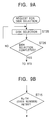
- the clamping operation and the detection of completion of the clamping operation are controlled according to a flow shown in FIG. 9.
- FIG. 8 shows a flow of a control procedure for reliably clamping a disk loaded and transferred from the loading slot 83 on the turntable 54.
- a large-diameter disk D having a diameter of 12 cm can be reliably clamped according to the flow shown in FIG. 8.
- the distance L between the actuator 31a of the first detection switch 31 and the actuator 32a of the second detection switch 32 is determined so that both the first and second detection switches 31 and 32 are simultaneously turned on by both the peripheral edge of a small-diameter disk Ds and the peripheral edge of a large-diameter disk D.
- the center of the disk Ds and the center of rotation of the turntable 54 can be precisely aligned in the Y-direction, as viewed from above.
- the center of the large-diameter disk D when both the detection switches 31 and 32 are turned on, the center of the large-diameter disk D is placed in an area slightly wider in the Y-direction than that of the small-diameter disk Ds.
- the center hole D1 of the large-diameter disk D can be reliably fitted on the positioning projection 54a of the turntable 54 by executing the control according to the flow shown in FIG. 8. That is, both the small-diameter disk Ds and the large-diameter disk D can be reliably clamped even when the first detection switch 31 and the second detection switch 32 are used to position both the disks.
- the flow shown in FIG. 8 applies to a case in which a large-diameter disk D is clamped.
- a small-diameter disk Ds as described above, after it is determined that the center of the disk Ds is aligned with the center of rotation of the turntable 54 when both the detection switches 31 and 32 are simultaneously turned on, a subsequent clamping operation is performed without executing the control shown in FIG. 8. In this case, clamping failure, such as misclamping, rarely occurs. However, such control operation may also be performed when the small-diameter disk Ds is used.
- abnormal loading operation can be detected in a case in which a disk having a nonstandard outer size is loaded, in a case in which a disk having a center hole of a nonstandard diameter is loaded, or in a case in which a ring-shaped adapter having a diameter of 12 cm that does not hold a small-diameter disk Ds having a diameter of 8 cm in its center is loaded. Accordingly, an ejecting operation can be immediately performed in this case.
- Step ST5 the actuation of one of the first detection switch 31 and the second detection switch 32 is waited for.
- the actuator 31a or 32a is pressed by the peripheral edge of the disk D that is moving in the guide groove 11a of the guide member 11, and one of the detection switches 31 and 32 is turned on (detection state), a clamping operation is performed in Step ST6.
- the sliding members 65 shown in FIG. 3B are moved in the Y2-direction, the driving chassis 51 is moved up, the large-diameter disk D that is being carried is slightly bent because its center portion (adjacent to the center hole D1) is pushed up by the positioning projection 54a of the turntable 54 in a state in which both edges in the X-direction thereof are held by the guide member 11 and the transfer rollers 23 and 24, as shown in FIG. 4.
- the center portion of the bent disk D is pressed against the turntable 54 by elastic resilient force.
- the disk D is transferred in the Y1-direction by the transfer rollers 23 and 24 while being bent, as shown in FIG. 4.
- the first detection switch 31 In a case in which the conveyed disk has a standard size and the first and second detection switches 31 and 32 normally operate, the first detection switch 31 must be first turned on in ST5 while the large-diameter disk D is being transferred in the Y1-direction.
- the center of the center hole D1 of the large-diameter disk D is placed offset by a small distance ⁇ from the center of rotation of the turntable 54 toward the Y2-side. Therefore, when clamping operation is performed in ST6, the upper surface of the positioning projection 54a of the turntable 54 is pressed against the disk D slightly offset from the center hole D1.
- the center hole D1 of the disk D is forcibly fitted on the positioning projection 54a of the turntable 54 by the resilient force of the bent disk D, and the clamper 56 clamps the disk D between the clamper 56 and the turntable 54 by using the force of the leaf spring 57.
- the actuator 32a of the second detection switch 32 is pressed by the peripheral edge of the disk D, and both the detection switches 31 and 32 are in an ON state (detection state) in ST7.
- the disk D will not move in the Y1-direction from the fitting position on the turntable 54 even when a Y1-direction transfer force of the transfer rollers 23 and 24 in the transfer mechanism 20 continuously acts on the disk D.
- the completion of clamping cannot be detected, for example, in a case in which both the detection switches 31 and 32 are not turned on in ST7 after one of the detection switches 31 and 32 is turned on in ST5, or in a case in which both the detection switches 31 and 32 are ON in ST7, and one or both of the detection switches 31 and 32 are turned off before a predetermined time to be measured in ST8 passes, that is, the state in which both the detection switches 31 and 32 are ON is canceled.
- a first cause of such a condition is that the disk D1 is not normally clamped although it conforms to the standard.
- a second cause is that the loaded disk D1 is nonstandard, and the diameter of the center hole D1 is extraordinarily large.
- the disk is shifted by the transfer force of the transfer mechanism 20 because the center hole is too large. Consequently, it is impossible to continue the state, in which both the detection switches 31 and 32 are ON, for a predetermined time.
- This also applies to a case in which a ring-shaped adapter that does not have a small-diameter disk Ds at its center is loaded.
- a third cause is that one of the first detection switch 31 and the second detection switch 32 is incapable of detection due to trouble.
- both the first and second detection switches 31 and 32 will not be simultaneously turned on. Therefore, it is impossible to obtain detection information that the disk is normally clamped.
- Step ST14 it is determined whether a predetermined number N 1 (odd number) of retries are performed. When it is determined that N 1 -number of retries are not performed, a retry process is performed.
- Step ST15 the transfer rollers 21, 22, 23, and 24 of the transfer mechanism 20 are reversed in ST15, and it is determined in ST7 whether or not both the detection switches 31 and 32 are ON.
- both the detection switches 31 and 32 are ON, it is checked in ST8 whether or not the ON state continues for a predetermined time.
- Step ST9 is performed.
- Step ST12 is performed.
- the disk is automatically ejected by operating the transfer mechanism 20 in the ejecting direction.
- operations other than the disk ejecting operation are not permitted, an "error" indication is displayed on the liquid crystal display panel 81 of the nose section 80, and a request for disk ejection is waited for.
- the transfer mechanism 20 is operated in the ejecting direction, and the disk is ejected to the loading slot 83.
- an ejecting operation may be automatically performed by operating the transfer mechanism 20 in the ejecting direction regardless of the type of the control button.
- the error handling process is performed in ST17 and subsequent steps.
- the number of retries at an odd number, when the transfer rollers 21, 22, 23, and 24 of the transfer mechanism 20 are stopped in ST17, the disk D can be stopped in a state in which the center of the disk D is placed offset from the center of rotation of the turntable 54 toward the loading slot 83.
- the transfer mechanism 20 can be operated in the ejecting direction in ST19 in a state in which the disk D is reliably held by the guide member 11 and the transfer mechanism 20. This allows the disk D to be reliably ejected after the clamping error occurs.
- the guide member 11 and the transfer mechanism 20 will not separate from the disk D and unclamp the disk D in a state in which the disk D is placed inside the disk apparatus 1. If the guide member 11 and the transfer mechanism 20 separate from the disk D although the detection switch 31 or 32 is in trouble, one of the detection switches 31 and 32 does not normally operate even when the guide member 11 and the transfer mechanism 20 are moved closer to each other later. Therefore, it is impossible to detect whether or not the disk D can be normally held therebetween. Also, the main control unit 61 cannot determine that the disk is held in the driving unit 50. As a result, the disk apparatus 1 fails while the disk remains therein, and the disk cannot be ejected later.
- the main control unit 61 cannot detect the completion of the disk clamping operation, for example, when none of the detection switches 31 and 32 are ON in ST5.
- Such a phenomenon occurs, for example, because the loaded disk D is too thin and is transferred with its peripheral edge deviating from both the actuators 31a and 32a of the detection switches 31 and 32, as shown in FIG. 5. Similarly, when both the first and second detection switches 31 and 32 are incapable of detection due to trouble, none of the detection switches 31 and 32 are ON in ST5.
- the transfer direction of the transfer mechanism 20 is reversed in ST21 so as to carry the disk toward the loading slot 83 (in the Y2-direction).
- ST22 it is checked whether or not one of the detection switches 31 and 32 is turned on within a predetermined time. When one of the detection switches 31 and 32 is turned on within the predetermined time, a disk clamping operation is tried in ST6.
- the disk is automatically ejected in ST19, or is ejected in response to an ejection request.
- the number of retries be set in ST23 so that the disk is stopped at the position where its center is placed offset from the center of rotation of the turntable 54 when the predetermined number of retries are completed.
- the disk can remain held between the guide member 11 and the transfer mechanism 20. Therefore, the disk can be ejected only by operating the transfer mechanism 20 in the disk ejecting direction, or only a disk ejecting request can be accepted. This can prevent the disk from being left in the disk apparatus 1 in a state in which detection is impossible.
- FIG. 9 shows a procedure for selecting any disk holder 41 from the stock section 3, drawing a disk held in the selected disk holder 41 in the Y2-direction, and clamping the disk by the turntable 54 and the clamper 56 in the driving unit 50.
- a retry is performed in ST14.
- a retry is also performed when it is determined that a state in which none of the detection switches 31 and 32 are ON continues for a predetermined time in ST20.
- the number of retries in ST15 is set at a predetermined even number N 2 .
- the number of retries in ST23 is similarly set.
- the first moving member 6 and the second moving member 7 are moved closer to each other, and the guide member 11 and the transfer mechanism 20 hold the disk clamped on the turntable 54.
- a small-diameter disk Ds having a diameter of 8 cm is simply ejected to the loading slot 83
- a large-diameter disk D having a diameter of 12 cm is simply ejected to the loading slot 83 or is transferred into the disk holder 41 in the stock section 3.
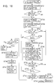
- FIG. 10 shows a flow of a control operation to be performed when a disk clamped on the turntable 54 is held between the guide member 11 and the transfer mechanism 20.
- the first moving member 6 and the second moving member 7 are moved closer to each other in ST31, and the opposing distance Wx between the guide member 11 and the transfer mechanism 20 is set so as to hold the disk D therebetween.
- the retry includes two stages.
- the first moving member 6 and the second moving member 7 are moved further apart from each other so as to increase the opposing distance between the guide member 11 and the transfer mechanism 20 in ST35, and the guide member 11 and the transfer mechanism 20 are separated from the peripheral edge of the disk D.
- ST36 the opposing distance Wx between the guide member 11 and the transfer mechanism 20 is decreased, and an operation of holding the disk D therebetween is performed again.
- the first stage there is a high probability of recovering from errors, for example, falling of the peripheral edge of the disk D off the guide groove 11a of the guide member 11 when decreasing the opposing distance Wx between the guide member 11 and the transfer mechanism 20, or separation of the peripheral edge of the disk D from the actuators 31a and 32a of the detection switches 31 and 32, as shown in FIG. 5, because of an insufficient thickness of the disk D.
- the number of first-stage retries carried out is measured.
- N 3 approximately three
- the opposing distance Wx between the guide member 11 and the transfer mechanism 20 is set to be slightly shorter, for example, by 0.5 mm than when the disk D on the turntable 54 is held therebetween.
- the disk D clamped on the turntable 54 is rotated at least once.
- the rotating operation can be performed by driving the transfer rollers 21, 22, 23, and 24 of the transfer mechanism 20, or by rotating the spindle motor 53.
- the transfer rollers 21, 22, 23, and 24 are driven three times, that is, forward, in reverse, and forward, each for approximately 50 ms.
- the peripheral edge of the disk D is deformed in a corrugated shape or the disk D is partially warped, even when the peripheral edge is separate from the actuators 31a and 32a, the probability that it will press the actuator 31a or 32a can be increased by rotating the disk D in ST40.
- the clamping error may occur, for example, because the disk D is extraordinarily warped, because both the detection switches 31 and 32 are incapable of detection due to trouble, or because the disk D does not lie on the turntable 54.
- an operation history of the disk apparatus 1 stored in the memory 62 of the main control unit 61 is checked in ST44.
- information that the disk D has been clamped by the driving unit 50 before or immediately before the occurrence of the error is not recorded in the operation history, it is determined in ST48 that the disk D is not held on the turntable 54, and a subsequent operation by the user is accepted. That is, operations of loading a new disk D, of selecting a disk D from the stock section 3, and of drawing a disk D selected from the stock section 3 into the driving unit 50 and clamping the disk D are accepted.
- the transfer mechanism 20 operates in the ejecting direction, and the disk D is automatically ejected to the loading slot 83.
- an "error" indication is displayed on the liquid crystal display panel 81, and the operation is stopped. After that, only an operation of pressing the EJECT button is accepted.
- the transfer mechanism 20 is operated to eject the disk D.
- the disk D may be ejected by operating any control button in the nose section 80, regardless of the type of the control button.
- the probability of ejecting the disk D can be increased. For example, in a case in which the first detection switch 31 and the second detection switch 32 cannot properly operate because of trouble, the disk D is not left in the disk apparatus 1, but is ejected reliably.
Landscapes
- Feeding And Guiding Record Carriers (AREA)
- Automatic Disk Changers (AREA)
- Automatic Analysis And Handling Materials Therefor (AREA)
Abstract
Description
Claims (10)
- A disk apparatus comprising:wherein said guide member has a pair of detectors arranged in the disk transfer direction with a predetermined distance, both said detectors being brought into a detection state by a peripheral edge of the disk when the disk reaches such a position as to be clamped by said rotating section, anda guide member extending in a disk transfer direction so as to guide a disk to be transferred;a transfer mechanism for applying a transfer force to the disk;a rotating section to be fitted in a center hole of the disk transferred by said transfer mechanism so as to apply a rotating force to the disk;a clamp mechanism for fitting said rotating section in the center hole of the disk; anda control section for controlling operation of said disk apparatus,
wherein said control section operates said clamp mechanism so that said rotating section is urged toward the disk when one of said detectors is brought into a detection state during the transfer of the disk, determines that a clamping operation of the disk is completed when both said detectors are brought into a detection state and the detection state continues for a predetermined time, and stops said transfer mechanism in response to the determination. - A disk apparatus according to claim 1, wherein said control section operates said transfer mechanism so as to reverse the disk transfer direction at least once after recognizing that both said detectors are brought into the detection state, and determines that the clamping operation of the disk is completed when both said detectors maintain the detection state for a predetermined time.
- A disk apparatus according to claim 1 or 2, wherein a retry for operating said transfer mechanism so as to reverse the disk transfer direction at least once is performed when one of said detectors is brought into a detection state during the transfer of the disk and both said the detectors are not brought into a detection state within a predetermined time after said rotating section is urged toward the disk.
- A disk apparatus according to claim 1 or 2, wherein said transfer mechanism transfers a disk loaded from a loading slot of said disk apparatus toward said rotating section.
- A disk apparatus according to claim 4, further comprising:wherein a retry for operating said transfer mechanism so as to reverse the disk transfer direction at least once is performed when none of said detectors are brought into a detection state within a predetermined time after loading of the disk is detected by said loading detector.a loading detector for detecting that the disk is loaded from said loading slot,
- A disk apparatus according to any preceding claim, further comprising:wherein said transfer mechanism transfers a disk selected from said plurality of disks stored in said stock section toward said rotating section.a stock section provided inside said disk apparatus so as to store a plurality of disks,
- A disk apparatus according to any preceding claim, wherein said guide member guides one side of the peripheral edge of the disk, said transfer mechanism opposes said guide member so as to apply the transfer force to the other side of the peripheral edge of the disk, said rotating section is urged toward the disk held by said guide member and said transfer mechanism, and the disk is pressed against said rotating section by elastic resilient force when the disk reaches such a position as to be clamped in a bent state on said rotating section.
- A disk apparatus according to claim 7, wherein said guide member has a guide groove extending in the disk transfer direction so as to receive the peripheral edge of the disk, actuators of said pair of detectors project in said guide groove, and said detectors are brought into the detection state when said actuators are pressed by the peripheral edge of the disk that moves in said guide groove.
- A disk apparatus according to claim 8, wherein said transfer mechanism holds the disk between said transfer mechanism and said guide groove of said guide member, and includes a plurality of transfer rollers that are arranged in the disk transfer direction.
- A disk apparatus according to any claim 7 to 9, further comprising:wherein a distance between said pair of detectors is determined so that said detectors are simultaneously brought into a detection state by a peripheral edge of the small-diameter disk and by or a peripheral edge of the large-diameter disk, anda disk-diameter distinguishing section for distinguishing whether the disk loaded from said loading slot of said disk apparatus is a large-diameter disk or a small-diameter disk; anda distance setting section for switching an opposing distance between said guide member and said transfer mechanism between a distance that allows a large-diameter disk to be transferred and a distance that allows a small-diameter disk to be transferred, on the basis of the result of distinction by said disk-diameter distinguishing section,
wherein said control section operates said clamp mechanism so as to press said rotating section against the disk when one of said detectors is brought into a detection state at least the during transfer of the large-diameter disk, and determines that the clamping operation of the disk is completed and stops said transfer mechanism when both said detectors are subsequently brought into a detection state and the detection state continues for a predetermined time.
Applications Claiming Priority (2)
| Application Number | Priority Date | Filing Date | Title |
|---|---|---|---|
| JP2002007518 | 2002-01-16 | ||
| JP2002007518A JP3838916B2 (en) | 2002-01-16 | 2002-01-16 | Disk unit |
Publications (3)
| Publication Number | Publication Date |
|---|---|
| EP1329886A2 true EP1329886A2 (en) | 2003-07-23 |
| EP1329886A3 EP1329886A3 (en) | 2004-01-02 |
| EP1329886B1 EP1329886B1 (en) | 2007-04-18 |
Family
ID=19191332
Family Applications (1)
| Application Number | Title | Priority Date | Filing Date |
|---|---|---|---|
| EP02258725A Expired - Lifetime EP1329886B1 (en) | 2002-01-16 | 2002-12-18 | Disk apparatus |
Country Status (5)
| Country | Link |
|---|---|
| US (1) | US6873481B2 (en) |
| EP (1) | EP1329886B1 (en) |
| JP (1) | JP3838916B2 (en) |
| CN (1) | CN1208774C (en) |
| DE (1) | DE60219584T2 (en) |
Families Citing this family (12)
| Publication number | Priority date | Publication date | Assignee | Title |
|---|---|---|---|---|
| WO2003036638A1 (en) * | 2001-10-24 | 2003-05-01 | Mitsubishi Denki Kabushiki Kaisha | Disk drive |
| JP3788395B2 (en) * | 2002-06-21 | 2006-06-21 | ソニー株式会社 | Disc loading device |
| SE525402C2 (en) * | 2003-06-19 | 2005-02-15 | Tetra Laval Holdings & Finance | Device and method for holding a source of radiation |
| JP2005235261A (en) * | 2004-02-17 | 2005-09-02 | Alpine Electronics Inc | Method and device for ejecting disk |
| JP4275079B2 (en) * | 2005-01-20 | 2009-06-10 | パナソニック株式会社 | Optical disk device |
| JP4628299B2 (en) * | 2006-04-13 | 2011-02-09 | アルパイン株式会社 | Disk unit |
| JP5541880B2 (en) * | 2009-05-07 | 2014-07-09 | 東芝アルパイン・オートモティブテクノロジー株式会社 | Optical disc playback apparatus and optical disc discharge control method |
| JP5594992B2 (en) * | 2009-08-07 | 2014-09-24 | アルパイン株式会社 | Disk unit |
| CN102072881B (en) * | 2009-11-23 | 2015-03-11 | 阿尔派株式会社 | Disc device |
| JP2011175714A (en) * | 2010-02-25 | 2011-09-08 | Hitachi-Lg Data Storage Inc | Optical disk device |
| CN112786079B (en) * | 2019-11-08 | 2023-02-17 | 光宝电子(广州)有限公司 | Disc taking and placing device for disc database |
| CN118130180B (en) * | 2024-05-07 | 2024-08-16 | 山西谐和源环保工程有限公司 | Air detection gas collection equipment |
Family Cites Families (4)
| Publication number | Priority date | Publication date | Assignee | Title |
|---|---|---|---|---|
| DE3732918A1 (en) * | 1987-09-30 | 1989-04-20 | Thomson Brandt Gmbh | CHARGING AND UNLOADING DEVICE OF A CD DEVICE |
| JPH09106607A (en) * | 1995-10-11 | 1997-04-22 | Nakamichi Corp | Changer-type disc-reproducing apparatus |
| US6288982B1 (en) * | 1997-03-03 | 2001-09-11 | Alpine Electronics, Inc. | Disk apparatus and method of locating/discriminating disks using the same |
| JPH10293954A (en) | 1997-04-17 | 1998-11-04 | Nakamichi Corp | Clamp mechanism |
-
2002
- 2002-01-16 JP JP2002007518A patent/JP3838916B2/en not_active Expired - Fee Related
- 2002-12-18 DE DE60219584T patent/DE60219584T2/en not_active Expired - Lifetime
- 2002-12-18 EP EP02258725A patent/EP1329886B1/en not_active Expired - Lifetime
-
2003
- 2003-01-13 US US10/341,313 patent/US6873481B2/en not_active Expired - Fee Related
- 2003-01-16 CN CN03100728.7A patent/CN1208774C/en not_active Expired - Fee Related
Also Published As
| Publication number | Publication date |
|---|---|
| EP1329886A3 (en) | 2004-01-02 |
| JP2003208743A (en) | 2003-07-25 |
| CN1433015A (en) | 2003-07-30 |
| US20030156508A1 (en) | 2003-08-21 |
| CN1208774C (en) | 2005-06-29 |
| DE60219584T2 (en) | 2007-12-27 |
| JP3838916B2 (en) | 2006-10-25 |
| EP1329886B1 (en) | 2007-04-18 |
| US6873481B2 (en) | 2005-03-29 |
| DE60219584D1 (en) | 2007-05-31 |
Similar Documents
| Publication | Publication Date | Title |
|---|---|---|
| EP1329886B1 (en) | Disk apparatus | |
| JP3875109B2 (en) | Disk unit | |
| US7073184B2 (en) | Disk apparatus | |
| JP5191165B2 (en) | Disk unit | |
| JP3838915B2 (en) | Disk unit | |
| JP3883871B2 (en) | Disk unit | |
| JP4311573B2 (en) | Disk unit | |
| JP4361040B2 (en) | Disk unit | |
| JP4311572B2 (en) | Disk storage type disk device | |
| JP4181156B2 (en) | Disk unit | |
| JP3894837B2 (en) | Disk unit | |
| JP3963665B2 (en) | Disk unit | |
| JP3875110B2 (en) | Disk unit | |
| JP2588512Y2 (en) | Disc player | |
| JP3963666B2 (en) | Disk unit | |
| JP4628299B2 (en) | Disk unit | |
| JP5403994B2 (en) | Disk unit | |
| JP3869773B2 (en) | Disk unit | |
| JP4100742B2 (en) | Disk unit | |
| JP2003217221A (en) | Disk drive | |
| CN101401162A (en) | Disc player, and method and program for controlling such disc player | |
| JP2003217219A (en) | Disk drive | |
| JP3856584B2 (en) | Recording medium insertion detection device | |
| JP2008071437A (en) | Disk housing type disk device | |
| EP1073049B1 (en) | Disk drive apparatus |
Legal Events
| Date | Code | Title | Description |
|---|---|---|---|
| PUAI | Public reference made under article 153(3) epc to a published international application that has entered the european phase |
Free format text: ORIGINAL CODE: 0009012 |
|
| AK | Designated contracting states |
Designated state(s): AT BE BG CH CY CZ DE DK EE ES FI FR GB GR IE IT LI LU MC NL PT SE SI SK TR |
|
| AX | Request for extension of the european patent |
Extension state: AL LT LV MK RO |
|
| PUAL | Search report despatched |
Free format text: ORIGINAL CODE: 0009013 |
|
| AK | Designated contracting states |
Kind code of ref document: A3 Designated state(s): AT BE BG CH CY CZ DE DK EE ES FI FR GB GR IE IT LI LU MC NL PT SE SI SK TR |
|
| AX | Request for extension of the european patent |
Extension state: AL LT LV MK RO |
|
| 17P | Request for examination filed |
Effective date: 20040607 |
|
| AKX | Designation fees paid |
Designated state(s): DE FR GB |
|
| 17Q | First examination report despatched |
Effective date: 20050211 |
|
| GRAP | Despatch of communication of intention to grant a patent |
Free format text: ORIGINAL CODE: EPIDOSNIGR1 |
|
| GRAS | Grant fee paid |
Free format text: ORIGINAL CODE: EPIDOSNIGR3 |
|
| GRAA | (expected) grant |
Free format text: ORIGINAL CODE: 0009210 |
|
| AK | Designated contracting states |
Kind code of ref document: B1 Designated state(s): DE FR GB |
|
| REF | Corresponds to: |
Ref document number: 60219584 Country of ref document: DE Date of ref document: 20070531 Kind code of ref document: P |
|
| ET | Fr: translation filed | ||
| PLBE | No opposition filed within time limit |
Free format text: ORIGINAL CODE: 0009261 |
|
| STAA | Information on the status of an ep patent application or granted ep patent |
Free format text: STATUS: NO OPPOSITION FILED WITHIN TIME LIMIT |
|
| 26N | No opposition filed |
Effective date: 20080121 |
|
| REG | Reference to a national code |
Ref country code: FR Ref legal event code: PLFP Year of fee payment: 14 |
|
| PGFP | Annual fee paid to national office [announced via postgrant information from national office to epo] |
Ref country code: GB Payment date: 20151221 Year of fee payment: 14 Ref country code: DE Payment date: 20151211 Year of fee payment: 14 |
|
| PGFP | Annual fee paid to national office [announced via postgrant information from national office to epo] |
Ref country code: FR Payment date: 20151221 Year of fee payment: 14 |
|
| REG | Reference to a national code |
Ref country code: DE Ref legal event code: R119 Ref document number: 60219584 Country of ref document: DE |
|
| REG | Reference to a national code |
Ref country code: DE Ref legal event code: R082 Ref document number: 60219584 Country of ref document: DE Representative=s name: SCHMITT-NILSON SCHRAUD WAIBEL WOHLFROM PATENTA, DE |
|
| GBPC | Gb: european patent ceased through non-payment of renewal fee |
Effective date: 20161218 |
|
| REG | Reference to a national code |
Ref country code: FR Ref legal event code: ST Effective date: 20170831 |
|
| PG25 | Lapsed in a contracting state [announced via postgrant information from national office to epo] |
Ref country code: FR Free format text: LAPSE BECAUSE OF NON-PAYMENT OF DUE FEES Effective date: 20170102 |
|
| PG25 | Lapsed in a contracting state [announced via postgrant information from national office to epo] |
Ref country code: GB Free format text: LAPSE BECAUSE OF NON-PAYMENT OF DUE FEES Effective date: 20161218 Ref country code: DE Free format text: LAPSE BECAUSE OF NON-PAYMENT OF DUE FEES Effective date: 20170701 |