EP1329672A2 - Energy collecting system and method of operating the same - Google Patents
Energy collecting system and method of operating the same Download PDFInfo
- Publication number
- EP1329672A2 EP1329672A2 EP02019222A EP02019222A EP1329672A2 EP 1329672 A2 EP1329672 A2 EP 1329672A2 EP 02019222 A EP02019222 A EP 02019222A EP 02019222 A EP02019222 A EP 02019222A EP 1329672 A2 EP1329672 A2 EP 1329672A2
- Authority
- EP
- European Patent Office
- Prior art keywords
- waterwheel
- electric power
- water
- heat source
- inverter
- Prior art date
- Legal status (The legal status is an assumption and is not a legal conclusion. Google has not performed a legal analysis and makes no representation as to the accuracy of the status listed.)
- Granted
Links
- 238000000034 method Methods 0.000 title claims description 11
- XLYOFNOQVPJJNP-UHFFFAOYSA-N water Substances O XLYOFNOQVPJJNP-UHFFFAOYSA-N 0.000 claims abstract description 158
- 238000005338 heat storage Methods 0.000 claims abstract description 37
- 238000004378 air conditioning Methods 0.000 claims abstract description 21
- 238000005381 potential energy Methods 0.000 claims description 13
- 238000005086 pumping Methods 0.000 claims description 7
- 239000008400 supply water Substances 0.000 claims description 5
- 238000010586 diagram Methods 0.000 description 14
- 239000000470 constituent Substances 0.000 description 4
- 230000006872 improvement Effects 0.000 description 3
- 238000010248 power generation Methods 0.000 description 2
- 230000008569 process Effects 0.000 description 2
- 230000001172 regenerating effect Effects 0.000 description 2
- 101150110971 CIN7 gene Proteins 0.000 description 1
- 101150110298 INV1 gene Proteins 0.000 description 1
- 101100397044 Xenopus laevis invs-a gene Proteins 0.000 description 1
- 238000010420 art technique Methods 0.000 description 1
- 239000003990 capacitor Substances 0.000 description 1
- 230000008878 coupling Effects 0.000 description 1
- 238000010168 coupling process Methods 0.000 description 1
- 238000005859 coupling reaction Methods 0.000 description 1
- 230000003247 decreasing effect Effects 0.000 description 1
- 230000000694 effects Effects 0.000 description 1
- 238000012423 maintenance Methods 0.000 description 1
- 238000012986 modification Methods 0.000 description 1
- 230000004048 modification Effects 0.000 description 1
- 239000004065 semiconductor Substances 0.000 description 1
Images






Classifications
-
- F—MECHANICAL ENGINEERING; LIGHTING; HEATING; WEAPONS; BLASTING
- F24—HEATING; RANGES; VENTILATING
- F24F—AIR-CONDITIONING; AIR-HUMIDIFICATION; VENTILATION; USE OF AIR CURRENTS FOR SCREENING
- F24F5/00—Air-conditioning systems or apparatus not covered by F24F1/00 or F24F3/00, e.g. using solar heat or combined with household units such as an oven or water heater
- F24F5/0007—Air-conditioning systems or apparatus not covered by F24F1/00 or F24F3/00, e.g. using solar heat or combined with household units such as an oven or water heater cooling apparatus specially adapted for use in air-conditioning
- F24F5/0017—Air-conditioning systems or apparatus not covered by F24F1/00 or F24F3/00, e.g. using solar heat or combined with household units such as an oven or water heater cooling apparatus specially adapted for use in air-conditioning using cold storage bodies, e.g. ice
-
- Y—GENERAL TAGGING OF NEW TECHNOLOGICAL DEVELOPMENTS; GENERAL TAGGING OF CROSS-SECTIONAL TECHNOLOGIES SPANNING OVER SEVERAL SECTIONS OF THE IPC; TECHNICAL SUBJECTS COVERED BY FORMER USPC CROSS-REFERENCE ART COLLECTIONS [XRACs] AND DIGESTS
- Y02—TECHNOLOGIES OR APPLICATIONS FOR MITIGATION OR ADAPTATION AGAINST CLIMATE CHANGE
- Y02E—REDUCTION OF GREENHOUSE GAS [GHG] EMISSIONS, RELATED TO ENERGY GENERATION, TRANSMISSION OR DISTRIBUTION
- Y02E10/00—Energy generation through renewable energy sources
- Y02E10/20—Hydro energy
-
- Y—GENERAL TAGGING OF NEW TECHNOLOGICAL DEVELOPMENTS; GENERAL TAGGING OF CROSS-SECTIONAL TECHNOLOGIES SPANNING OVER SEVERAL SECTIONS OF THE IPC; TECHNICAL SUBJECTS COVERED BY FORMER USPC CROSS-REFERENCE ART COLLECTIONS [XRACs] AND DIGESTS
- Y02—TECHNOLOGIES OR APPLICATIONS FOR MITIGATION OR ADAPTATION AGAINST CLIMATE CHANGE
- Y02E—REDUCTION OF GREENHOUSE GAS [GHG] EMISSIONS, RELATED TO ENERGY GENERATION, TRANSMISSION OR DISTRIBUTION
- Y02E60/00—Enabling technologies; Technologies with a potential or indirect contribution to GHG emissions mitigation
- Y02E60/14—Thermal energy storage
-
- Y—GENERAL TAGGING OF NEW TECHNOLOGICAL DEVELOPMENTS; GENERAL TAGGING OF CROSS-SECTIONAL TECHNOLOGIES SPANNING OVER SEVERAL SECTIONS OF THE IPC; TECHNICAL SUBJECTS COVERED BY FORMER USPC CROSS-REFERENCE ART COLLECTIONS [XRACs] AND DIGESTS
- Y02—TECHNOLOGIES OR APPLICATIONS FOR MITIGATION OR ADAPTATION AGAINST CLIMATE CHANGE
- Y02E—REDUCTION OF GREENHOUSE GAS [GHG] EMISSIONS, RELATED TO ENERGY GENERATION, TRANSMISSION OR DISTRIBUTION
- Y02E60/00—Enabling technologies; Technologies with a potential or indirect contribution to GHG emissions mitigation
- Y02E60/16—Mechanical energy storage, e.g. flywheels or pressurised fluids
-
- Y—GENERAL TAGGING OF NEW TECHNOLOGICAL DEVELOPMENTS; GENERAL TAGGING OF CROSS-SECTIONAL TECHNOLOGIES SPANNING OVER SEVERAL SECTIONS OF THE IPC; TECHNICAL SUBJECTS COVERED BY FORMER USPC CROSS-REFERENCE ART COLLECTIONS [XRACs] AND DIGESTS
- Y02—TECHNOLOGIES OR APPLICATIONS FOR MITIGATION OR ADAPTATION AGAINST CLIMATE CHANGE
- Y02P—CLIMATE CHANGE MITIGATION TECHNOLOGIES IN THE PRODUCTION OR PROCESSING OF GOODS
- Y02P70/00—Climate change mitigation technologies in the production process for final industrial or consumer products
- Y02P70/50—Manufacturing or production processes characterised by the final manufactured product
Definitions
- the present invention relates to an energy collecting system and a method of operating the same in which energy is collected through generation of electric power by a waterwheel using water used by, for example, an air-conditioning load or the like in a building.
- an air-conditioning system of heat storage type in which a heat source is operated using inexpensive nighttime electric power to store generated heat in a heat storage.
- the stored heat is fed from the heat storage to the load, i.e., an air conditioner to achieve air-conditioning operation.
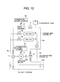
- Fig. 12 is a diagram showing a configuration of an example of the prior art, namely, an open-loop air-conditioning system of heat storage type.
- the configuration includes a water pump 1 which feeds water from a heat storage 16 to supply the water via a water supply pipe 4a to a heat source 4 and a both-end motor 2 of which one shaft end is directly coupled with the water pump using a shaft coupling to drive the water pump.
- the other shaft end is coupled with a waterwheel 12 via a clutch 12b.
- the waterwheel is disposed at a position at which potential energy of water discharged from the heat source can be completely collected.
- Numerals 18 and 19 indicate electric power sources
- numeral 5 is a two-way valve to adjust a quantity of heat generated by the heat source
- numeral 6a is a water supply pipe connecting the heat source to the waterwheel
- numeral 6 is an expansion tank associated with the water supply pipe.
- the tank 6 breaks a siphon to apply a head of the supplied water (potential energy thereof) to the waterwheel.
- a vacuum breaking valve may be disposed depending on cases.
- Numeral 12c indicates a water supply pipe to return the water from the waterwheel to the heat storage. That is, the water supplied to the heat source 4 by the water pump 1 is heated by the heat source and is then fed to the waterwheel 12.
- the waterwheel 12 is operated by the potential energy of the water to generate power and then imparts the power to the both-end motor 2.
- the load of the motor becomes lower than that of the water pump, the discrepancy therebetween corresponds to the power imparted from the waterwheel.
- the water from the waterwheel then returns to the heat storage.
- the secondary-side system S 2 is a load of an air conditioner or the like and supplies water from the heat storage 16 via a water supply pipe 7a to an air han (air handling unit) 8 and a fan coil 9 by a pump 7.
- the air han 8 includes an adjusting valve 8a to adjust a quantity of heat.
- the fan coil 9 also includes a similar adjusting valve 9a. The water of which heat is radiated is returned via the water supply pipe 7b to the heat storage 16.
- Fig. 13 shows an operating characteristic graph of a pump and a waterwheel in an example of the prior art.
- a total water pumping-up process of the pump, an effective head of the waterwheel, and power of the pump and the waterwheel are indicated along an ordinate.
- a water flow rate is indicated along an abscissa.
- a curve A is a curve of Q,H performance of the pump and a curve C is a curve of shaft power when the waterwheel is not operated.
- the total water pumping-up process is required to operate only the water pump to supply water at a flow rate of Q0 to the water supply system shown in Fig. 9.
- the operation point in this operation is point 04 on the curve A.
- Power consumed in this operation is L1 indicated by pump shaft power, and the operation point is point O1 on the curve C.
- a curve B indicates an effective head of the waterwheel (pressure head difference between the inlet and the outlet of the waterwheel). This means that when water flows at a flow rate of Q0, a pressure head difference (effective head) of H1 occurs between the inlet and the outlet of the waterwheel, and this potential energy is absorbed to generate power as below.
- a curve D is a power curve when the water pump and the waterwheel are operated. Power consumed in the operation is L2 indicated by pump shaft power and the operation point is point O2 on the curve D. That is, when the flow rate is Q0, power generated by the waterwheel is L3.
- the power collection ratio (L3/L1) is about 20% to about 30%.
- the conventional apparatus effectively uses potential energy of the pumped-up water passed through the heat source.
- JP-A-50-128801 (a power collection pumping machine) and JP-A-50-49701 (a power collection pumping machine) describes known examples of this apparatus.
- the prior art technique uses a clutch to directly couple a motor with a waterwheel and there is a problem of improvement of transfer efficiency of the clutch.
- the energy collected by the waterwheel is power and there is a problem that the power cannot be used in this case, in consideration of structure, for any other load in the building.
- JP-A-5-10245 (an electric power generator using waterwheel of paddle-wheel type) is a known example of waterwheel electric power generation using a waterwheel in a dam, a paddy field, or a watercourse.
- an energy collecting system comprising as basic units a heat storage disposed in a lower section of a building; a heat source disposed in an upper section of the building for imparting heat to water supplied from the heat storage by electric power from a commercial power source and thereby producing cool or warm water; a primary cool/warm water pump for pumping up the water from the heat storage and supplying the water via a sucking pipe to the heat source; a water supply pipe disposed between a discharge outlet of the primary cool/warm water pump and the heat source; a water supply pipe for returning water from a discharge outlet of the heat source to the heat storage; an expansion tank or a vacuum breaking valve disposed in a highest section of the water supply pipe; a waterwheel disposed in a lowest section of the water supply pipe for collecting potential energy of the water discharged from the heat source; an electric power generator rotated by torque generated by the waterwheel to generate electric power; an inverter connected to an output port of the electric power generator for converting a voltage and a frequency of electric power generated
- a pressure sensor disposed in the vicinity of the waterwheel senses pressure at the position. When the water pressure becomes equal to or more than a predetermined value, an automatic valve disposed in the vicinity of the waterwheel is opened.
- an energy collecting system in a building wherein a water pump on a secondary-side system to supply water to a group of air-conditioning loads is driven by an inverter, a waterwheel is operated by potential energy of water used by the air-conditioning loads, an electric power generator is operated by torque generated by the waterwheel, power generated by the electric power generator is converted by a regenerative converter into direct-current (dc) power, and positive-side dc power P thereof and negative-side dc power N thereof are outputted to dc terminals P and N of an inverter for the water pump.
- dc direct-current
- the system of the present invention is configured as above and operates as follows.
- the present invention is not limited to a system or a facility arranged in a building. That is, the configuration includes a heat storage for storing water fed from a heat source, a heat source for producing cool or warm water using water supplied from the heat storage, a pump for supplying the water from the heat storage to the heat source, a motor for driving the pump, a waterwheel rotated by the water supplied from the heat source, an electric power generator driven by the waterwheel for generating electric power, an inverter connected to an output port of the electric power generator, a system collaboration unit disposed between the motor and a commercial power source for conducting a change-over operation between a system connecting the commercial power source to the motor and a system connecting the inverter to the commercial power source, and a connecting line for connecting an electric path between the system collaboration unit and the motor to an output port of the inverter.
- Fig. 1 shows a configuration of a first embodiment of the present invention.
- the both-end motor is replaced with a general motor (a non-both-end motor), the water pump is separated from the waterwheel, an electric power generator is disposed in the waterwheel (or an integral type of these units is also available), and an inverter is connected to an output port of the electric power generator.
- a system collaboration unit 20 is disposed between a motor 2 to drive the water pump 1 and a power source 19.
- the system collaboration unit 20 is connected via a cable 21 to the motor 2.
- an output of the inverter is connected via a cable 14a to the motor 2.
- the system collaboration unit 20 When the waterwheel is not operating, the system collaboration unit 20 operates to supply power from a commercial power source 19 to the motor 2. When the waterwheel is operating and power generated by the electric power generator 13 is insufficient according to a load state of the water pump 1, the system collaboration unit 20 operates to supply power obtained by adding power from the commercial power source to the power generated by the electric power generator 13. When there remains unused power in the generated power, the unused power is returned from the inverter to the commercial power source via the system collaboration unit.
- the units or devices assigned with the same reference numerals are the same as those of Fig. 9, and hence description thereof will be avoided.
- Fig. 2 shows an operating characteristic of the pump and the waterwheel of the first embodiment of the present invention.
- the components assigned with the same reference numerals are the same as those of Fig. 10 and hence description thereof will be avoided.
- power L3 generated by a combination of "waterwheel-electric power generator-inverter” and power L2 from the commercial power source are used.
- an insufficient power of the power generated by the waterwheel is supplied from the commercial power source via the system collaboration unit.
- the power collection ratio (L3/L1) is about 40% to about 60% and is improved when compared with the power collection ratio of the prior art.
- Fig. 3 Description will be given of a second embodiment by referring to Fig. 3.
- the load of the electric power generator is changed from the motor to drive the primary cool/warm pump to the heat source.
- numeral 520 is a system collaboration unit disposed between the commercial power source 18 and a power source terminal of the heat source 4.
- An output from the inverter 14 is connected via a cable 14a to an electric path 521 of the system collaboration unit. That is, when the waterwheel is not operating, the system collaboration unit 520 operates to supply power from the commercial power source 18 to the heat source 4.
- the system collaboration unit 520 When the waterwheel is operating and if power generated by the electric power generator 13 is insufficient according to a load state of the heat source 4, the system collaboration unit 520 operates to supply power obtained by adding the power generated by the electric power generator 13 to the power from the commercial power source 18. If there remains unused power in the power generated by the power generator 13, the unused power is returned from the inverter via the system collaboration unit to the commercial power source.
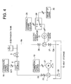
- Fig. 4 Power generated by the waterwheel is supplied to a group of various loads such as lighting apparatuses in a building.
- numeral 30 indicates a group of various loads such as lighting apparatuses in a building and numeral 29 is a power system change-over unit.
- the change-over unit 29 is set to a c-a side, the group of loads is connected to the commercial power source.
- the change-over unit 29 is set to a c-b side, the group of loads is connected to the electric power generator side.
- the change-over unit 29 is set to a c-b side to supply power generated by the electric power generator 13.
- the change-over unit 29 is set to a c-a side to supply power from the commercial power source.
- a fourth embodiment will be described by referring to Fig. 5.
- the group of loads when the group of loads imposes a high load and the power generated by the electric power generator 13 is insufficient, the power from the electric power generator 13 is added to that from the commercial power source.
- the group of loads 30 can be powered from the electric power generator 13 and from the commercial power source 28.
- An inverter 14 is connected to the electric power generator 13
- a system collaboration unit 720 is connected between the commercial power source 28 and the group of loads 30, and a cable 14a connects an electric path connecting the system collaboration unit 720 to a power source terminal of the group of loads 30 to an output from the inverter.
- a bypass pipe 29a and a bypass valve 29 are arranged to bypass valves before and after the waterwheel 12 and a pressure gauge 31a and a pressure sensor 31 are disposed on the inlet side of the waterwheel and a pressure gauge 30a and a pressure sensor 30 are disposed on the outlet side of the waterwheel.
- the gate valves 26 and 27 are closed and the gate valve 29 is opened to return the water having passed the heat source to the heat storage via the water supply pipe 6a, the bypass pipe 29a, and the valve 29 in this sequence.
- the heat source can be operated also during maintenance of the waterwheel 12, the electric power generator 13, and units associated therewith.
- Fig. 7 shows the operations and control procedures in a flowchart. That is, to start operation, the inlet valve of the waterwheel is opened, the outlet value thereof is closed, and the bypass valve thereof is closed in step 1.
- the heat source is powered.
- the motor to drive the primary cool/warm water pump is powered in step 3.
- an operation request signal is transmitted from the heat source side to the primary cool/warm water pump.
- step 5 the primary cool/warm water pump receives the operation request signal and operates the motor to drive the primary cool/warm water pump. The pump then sends an operation answer signal to the heat source.
- step 6 when a predetermined period of time lapses after the heat source receives the answer signal indicating the operation of the motor to drive the primary cool/warm water pump, the heat source starts its operation.
- step 7 when a predetermined period of time lapses after the heat source starts its operation, the waterwheel outlet valve is opened. As a result, the waterwheel starts its operation and the electric power generator also starts its operation.
- step 8 power generated by the electric power generator is supplied via the inverter to the primary cool/warm water pump.
- step 9 to stop the waterwheel. This stops the electric power generator.
- step 10 the system stops supplying the generated power and stops the inverter. The system then stops supplying power to the motor to drive the primary cool/warm water pump.
- step 10 a stop request signal is sent from the heat source side to the primary cool/warm water pump side and the heat source stops its operation.
- step 11 the motor to drive the primary cool/warm water pump receives the stop request signal and stops its operation.
- step 12 the motor returns a stop answer signal to the heat source.
- the system turns off power to the motor and power to the heat source.
- the motor to drive the primary cool/warm water pump is used as an example of the load of the electric power generator.
- the load may be a heat source or another load such as a lighting apparatus in a building.
- a seventh embodiment by referring to Fig. 8.
- the embodiment is implemented by further modifying the sixth embodiment to conduct an automatic and collaborative operation. Therefore, the gate valves 26, 27, and 29 of Fig. 6 are modified to automatic valves.
- the operations and control procedures are specified for the controller of the heat source, the motor to drive the primary cool/warm water pump, the electric power generator, the inverter, and the units as loads such that these constituent components automatically and mutually conduct operations in a collaborative way.
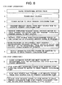
- Fig. 8 shows the operations and the control procedures in a flowchart.
- step 7 is added to Fig. 7 to open the waterwheel outlet and inlet valves when the waterwheel inlet pressure becomes equal to or more than a predetermined pressure to automatically operate the waterwheel 12, the electric power generator 13, and units associated therewith.
- step 9 is similarly added to Fig. 7 to close the waterwheel outlet and inlet valves to automatically the waterwheel 12, the electric power generator 13, and units associated therewith.
- the other operations are the same as those of Fig. 7 and hence description thereof will be avoided. Through the operation, the operation management becomes easier without any risk of erroneous operations.
- the open control condition of the waterwheel inlet and outlet valves during the operation includes that the heat source is operating and the inlet valve pressure is equal to or more than a predetermined pressure. When both conditions are satisfied, the open control is carried out. As a result, the operation is guaranteed and the overall system operates in a collaborative way.
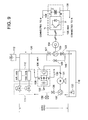
- Fig. 9 shows a configuration of a specific embodiment of the present invention.
- the both-end motor 2 is replaced with a general motor 131 (a non-both-end motor) to separate the water pump 107 from the waterwheel 109 in the secondary-side system to supply water to air-conditioning loads.
- An electric power generator 134 is disposed in the waterwheel 109 (or an integral type of these units is also available).
- An inverter 135 (INV2) is connected to an output port of the electric power generator 134. Power generated by the power generator 134 is converted into a dc voltage by the inverter 135 including semiconductor devices such as a power transistor Tr and a flywheel diode D. The power is then smoothed by a capacitor C.
- the inverter 135 is well known, for example, is an inverter using pulse width modulation (PWM) control and hence detailed description thereof will be avoided.
- PWM pulse width modulation
- the positive side P and the negative side N of the dc voltage output from the inverter 135 are respectively connected to the positive side P and the negative side N of a dc intermediate circuit of an inverter 136 (INV1)to drive the motor 131.
- the inverter 136 is also well known and is, for example, an inverter using PWM control and hence detailed description thereof will be avoided.
- the motor 131 to drive the water pump 107 is driven by the inverter 136.
- the inverter 136 is used because when the air-conditioning load varies, an energy saving operation is conducted by accordingly lowering the rotary speed of the pump.
- the dc voltage terminals P and N of the inverter 135 are respectively connected to the dc voltage terminals P and N of the inverter 136 using cables 138 and 139, respectively.
- the power generated by the electric power generator 134 can be supplied using a direct current to the inverter 136 on the water pump side. Therefore, it is not required to convert the power into an alternating current, and a simple and inexpensive configuration can be implemented without requiring a system collaboration unit.
- Fig. 10 shows an electric system of Fig. 9.
- the constituent components assigned with the same reference numerals are the same as those shown in Fig. 1, and hence description thereof will be avoided.
- numeral 103 indicates a commercial power source
- numeral 132 is a wattmeter
- ELB indicates an electric leakage breaker.
- the water pump 107 and the motor 131 are driven by the inverter 136 using power only from the commercial power source 103. Water is supplied by the operation of the water pump 107 to each air-conditioning load 110.
- the waterwheel 109 and the electric power generator 134 start operation to supply dc power from the inverter 135 via the cables 138 and 139 to the dc voltage terminals P and N of the inverter 136.
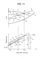
- Fig. 11 shows a graph of an operating characteristic of the water pump 107 and the waterwheel 109 in the embodiment of the present invention.
- the water pump 107 is controlled by the inverter 136 to keep a terminal pressure at a fixed value (the rotary speed of the pump is controlled to keep the terminal pressure of the pipe at a fixed value such that a pump discharge pressure is on a pipe resistance curve E).
- the items assigned with the same reference numerals are the same as those of Fig. 5, and hence description thereof will be avoided.
- the shaft power is indicated by a curve I 2 and the operation points are respectively O 4 and O 4 '.
- the inverter 136 is operated by a frequency of N 2 , and the water pump 107 has performance on a curve G.
- the shaft power is indicated by a curve I 3 and the operation points are respectively O 6 and O 6 '.
- the operation is conducted on a curve L connecting the points O 1 , O 4 , and O 6 of the shaft power.
- the waterwheel generates torque using potential energy of the water, and power is generated by the electric power generator 134 corresponding to shaft power L3.
- power is generated in accordance with the variation in a similar way.
- the water pump 107, the waterwheel 109, and the electric power generator 134 are simultaneously operated, a curve L4 is obtained.
- the power supplied from the commercial power source 103 is reduced as much as there is power generated by the electric power generator 134.
- Point O 3 in the diagram indicates a point at which the waterwheel 109 is efficiently operated by a flow rate of Q 3 and the electric power generator 134 generates electric power.
- the power collection ratio (L3/L1) is about 40% to about 60% and is improved as compared with the collection ratio of the prior art.
- the power generated by the electric power generator 134 is converted by the inverter 135 into a direct current to be supplied to the terminals P and N of the inverter 136 to drive the water pump 107 in a building.
- the power can be supplied not only to the inverter 136, but may also be supplied to any inverter of another facility. Since the terminals P and N of the inverter 135 are connected to the terminals P and N of the inverter 136 using a cable, when the cable becomes long, wiring loss is increased. Both inverters may be collectively arranged in one control board. As a result, the wiring loss can be improved.
- the power generated by the electric power generator is supplied as dc power via an inverter to another inverter, the power is not converted into an alternating current. Therefore, a simple and inexpensive system can be constructed without requiring a system collaboration unit.
Landscapes
- Engineering & Computer Science (AREA)
- Life Sciences & Earth Sciences (AREA)
- Sustainable Development (AREA)
- Chemical & Material Sciences (AREA)
- Combustion & Propulsion (AREA)
- Mechanical Engineering (AREA)
- General Engineering & Computer Science (AREA)
- Control Of Eletrric Generators (AREA)
- Supply And Distribution Of Alternating Current (AREA)
- Other Liquid Machine Or Engine Such As Wave Power Use (AREA)
Abstract
Description
Claims (16)
- An energy collecting system, comprising:a heat storage (16) ;a heat source (4) for imparting heat to water supplied from the heat storage by electric power from a commercial power source (19) and thereby producing cool or warm water;a primary cool/warm water pump (1) for pumping up the water from the heat storage and supplying the water via a sucking pipe to the heat source;a motor (2) for driving the primary cool/warm water pump;a water supply pipe disposed between a discharge outlet of the primary cool/warm water pump and the heat source;a water supply pipe (7b) for returning water from a discharge outlet of the heat source to the heat storage;an expansion tank (6) or a vacuum breaking valve disposed in a highest section of the water supply pipe;a waterwheel (12) disposed in a lowest section of the water supply pipe for collecting potential energy of the water discharged from the heat source; andan electric power generator (13) rotated by torque generated by the waterwheel to generate electric power.
- The system of claim 1, comprising:an inverter connected to an output port of the electric power generator for converting a voltage and a frequency of electric power generated by the electric power generator into a desired voltage and a desired frequency;a system collaboration unit between the motor and a commercial power source for changing a system from the commercial power source to a side of the motor or from the inverter to a side of the commercial power source; anda cable for connecting an output port of the inverter to an electric path between the system collaboration unit and the motor or to an electric path between the system collaboration unit and the heat source.
- The system of claim 2, wherein the motor or the heat source
is driven by electric power obtained by adding the power generated by the waterwheel to the power of the commercial power source. - The system of claim 1, wherein the electric power generated by the electric power generator is supplied to a load such as a lighting apparatus in a machine room.
- The system of claim 1, comprising an electric power change-over unit for changing a system, when power is not being generated, from a commercial power source to a load side and for changing the system, when power is being generated, from the electric power generator to a load side. wherein the electric power generated by the electric power generator is supplied to a load such as a lighting apparatus in a machine room.
- The system of claim 1, comprising:an inverter for converting the generated electric power desired by a load connected to an output port of the electric power generator into a voltage and a frequency;a system collaboration unit between the load and a commercial power source for changing a system from the commercial power source to a side of the load or from the inverter to a side of the commercial power source; anda cable for connecting an electric path between the system collaboration unit and the load to an output port of the inverter.
- The system of any preceding claim, comprising:a bypass pipe and a bypass valve bypassing the waterwheel; andpressure sensors disposed at an inlet and an output of the waterwheel.
- A method of operating an energy collecting system comprising:wherein the steps below:a heat storage (16);a heat source (4) for imparting heat to water supplied from the heat storage by electric power from a commercial power source and thereby producing cool or warm water;a commercial power source (19) for supplying electric power to the heat source;a primary cool/warm water pump (1) for pumping up the water from the heat storage and supplying the water via a sucking pipe to the heat source;a motor (2) for driving the primary cool/warm water pump;a water supply pipe disposed between a discharge outlet of the primary cool/warm water pump and the heat source;a water supply pipe for returning water from a discharge outlet of the heat source to the heat storage;an expansion tank (6) or a vacuum breaking valve disposed in a highest section of the water supply pipe;a waterwheel (12) disposed in a lowest section of the water supply pipe for collecting potential energy of the water discharged from the heat source;an electric power generator rotated by torque generated by the waterwheel to generate electric power; andan inverter connected to an output port of the electric power generator, the inverter converting the generated electric power desired by a load side into a voltage and a frequency and supplying the power to the motor to drive the primary cool/warm water pump,
<To start operation><To stop operation>(a) Open a waterwheel inlet valve, close a waterwheel outlet valve, and close a waterwheel bypass valve.(b) Power the heat source.(c) Power the motor to drive the primary cool/warm pump.(d) Transmit a request signal from the heat source side to operate the primary cool/warm pump.(e) Receive the operation request signal, operate the motor to drive the primary cool/warm pump, and transmit an operation answer signal to the heat source.(f) Operate the heat source when a predetermined period of time lapses after the operation answer signal is received.(g) When a predetermined period of time lapses after the heat source is operated, close the waterwheel outlet valve and operate the waterwheel. Operate the electric power generator.(h) Supply generated electric power via the inverter to the motor to drive the primary cool/warm pump.(a) Close the waterwheel outlet valve and stop the waterwheel. Stop the electric power generator.(b) Stop supplying the generated power. stop the inverter. Stop supplying power to the motor to drive the primary cool/warm pump.(c) Transmit a stop request signal from the heat source side to the primary cool/warm pump side. Stop the heat source.(d) Receive the stop request signal, stop the motor to drive the primary cool/warm pump, and return a stop answer signal to the heat source.(e) Interrupt the power to the motor to drive the primary cool/warm pump and interrupt the power to the heat source. - A method of operating an energy collecting system comprising:wherein the respective units automatically and collaboratively operate according to steps below:a heat storage (16);a heat source (4) for imparting heat to water supplied from the heat storage by electric power from a commercial power source and thereby producing cool or warm water;a commercial power source (19) for supplying electric power to the heat source;a primary cool/warm water pump (1) for pumping up the water from the heat storage and supplying the water via a sucking pipe to the heat source;a motor (2) for driving the primary cool/warm water pump;a water supply pipe disposed between a discharge outlet of the primary cool/warm water pump and the heat source;a water supply pipe for returning water from a discharge outlet of the heat source to the heat storage;an expansion tank (6) or a vacuum breaking valve disposed in a highest section of the water supply pipe;a waterwheel (12) disposed in a lowest section of the water supply pipe for collecting potential energy of the water discharged from the heat source;an automatic valve disposed to bypass the waterwheel;an automatic valve disposed in the an inlet or outlet of the waterwheel;pressure sensors disposed in the outlet and the inlet of the waterwheel;an electric power generator (13) rotated by torque generated by the waterwheel to generate electric power; andan inverter connected to an output port of the electric power generator, the inverter converting the generated electric power desired by a load side into a voltage and a frequency and supplying the power to the motor to drive the primary cool/warm water pump,
<To start operation><To stop operation>(a) Close the waterwheel bypass valve.(b) Power the heat source.(c) Power the motor to drive the primary cool/warm pump.(d) Transmit a request signal from the heat source side to operate the primary cool/warm pump.(e) Receive the operation request signal, operate the motor to drive the primary cool/warm pump, and transmit an operation answer signal to the heat source.(f) Operate the heat source when a predetermined period of time lapses after the operation answer signal is received.(g) When pressure at the waterwheel inlet reaches predetermined pressure, the automatic valves in the outlet of the waterwheel open and the waterwheel operates, the electric power generator operating in association therewith.(h) Supply generated electric power via the inverter to the motor to drive the primary cool/warm pump.(a) When a predetermined period lapses after the heat source is operated, close the automatic outlet and inlet valves of the waterwheel and stop the waterwheel. Stop the electric power generator.(b) Stop supplying the generated power, stop the inverter, stop supplying power to the motor to drive the primary cool/warm pump.(c) Transmit a stop request signal from the heat source side to the primary cool/warm pump side.(d) Receive the stop request signal, stop the motor to drive the primary cool/warm pump, and return a stop answer signal to the heat source.(e) Interrupt the power to the motor to drive the primary cool/warm pump and interrupt the power to the heat source. - The of claim 8, comprising a step of completely opening the automatic valves in the waterwheel outlet and inlet when the heat source operates and the pressure sensor in the waterwheel inlet senses the predetermined pressure.
- An energy collecting system, wherein:a water pump to supply water to a group of air-conditioning loads is driven by an inverter;a waterwheel (12) is operated by potential energy of water used by the air-conditioning loads;an electric power generator (13) is operated by torque generated by the waterwheel; andpower generated by the electric power generator is converted by an inverter into direct-current (dc) power.
- The system of claim 11, wherein the dc power is returned as dc power of the said inverter or of an inverter other than the said inverter.
- An energy collecting apparatus, comprising:a heat storage (16);a water pump of a secondary system for pumping up water from the heat storage and supplying the water to a group of air-conditioning loads;a first inverter for driving the water pump;a first water supply pipe disposed between a discharge outlet of the water pump and the group of air-conditioning loads;a second water supply pipe for returning water discharged from a discharge outlet of the group of air-conditioning loads to the heat storage;an expansion tank (6) or a vacuum breaking valve disposed in a highest section of the second water supply pipe;a waterwheel (12) disposed in a lower section of the second water supply pipe for collecting potential energy of the water discharged from the group of air-conditioning loads; andan electric power generator (13) rotated by torque generated by the waterwheel to generate electric power.
- The apparatus of claim 13, comprising:wherein the dc power generated by the second inverter is returned to the first inverter.a second inverter connected to an output port of the electric power generator to generate dc power; andmeans for connecting a dc section of the second inverter to the first inverter or to an inverter other than the second inverter,
- The apparatus of claim 13 or 14, wherein the first and second inverters are incorporated in a control board.
- An energy collecting system, comprising:a heat storage (16) for storing therein water obtained from a heat source;a heat source (4) for producing cool or warm water using water from the heat storage;a pump for supplying the water from the heat storage to the heat source;a motor (2) for driving the pump;a waterwheel (12) rotated by the water supplied from the heat source;an electric power generator (13) driven by the waterwheel to generate electric power;an inverter connected to an output port of the electric power generator;a system collaboration unit (20) disposed between the motor (2) and a commercial power source (19),the system collaboration unit conducting a change-over operation between a system connecting the commercial power source to the motor and a system connecting the inverter to the commercial power source; anda connecting line for connecting an electric path between the system collaboration unit and the motor to an output port of the inverter.
Applications Claiming Priority (4)
| Application Number | Priority Date | Filing Date | Title |
|---|---|---|---|
| JP2002008369 | 2002-01-17 | ||
| JP2002008369 | 2002-01-17 | ||
| JP2002087396 | 2002-03-27 | ||
| JP2002087396 | 2002-03-27 |
Publications (3)
| Publication Number | Publication Date |
|---|---|
| EP1329672A2 true EP1329672A2 (en) | 2003-07-23 |
| EP1329672A3 EP1329672A3 (en) | 2003-09-10 |
| EP1329672B1 EP1329672B1 (en) | 2006-10-11 |
Family
ID=26625551
Family Applications (1)
| Application Number | Title | Priority Date | Filing Date |
|---|---|---|---|
| EP02019222A Expired - Lifetime EP1329672B1 (en) | 2002-01-17 | 2002-08-27 | Energy collecting system and method of operating the same |
Country Status (6)
| Country | Link |
|---|---|
| US (3) | US6698223B2 (en) |
| EP (1) | EP1329672B1 (en) |
| JP (1) | JP4824097B2 (en) |
| DE (1) | DE60215293T2 (en) |
| DK (1) | DK1329672T3 (en) |
| TW (1) | TW587131B (en) |
Cited By (1)
| Publication number | Priority date | Publication date | Assignee | Title |
|---|---|---|---|---|
| EP2116720A3 (en) * | 2008-05-05 | 2010-10-06 | Günter Hirr | Hydroelectric power plant with waste heat recovery and integration of a heat pump |
Families Citing this family (8)
| Publication number | Priority date | Publication date | Assignee | Title |
|---|---|---|---|---|
| JP2004129314A (en) * | 2000-03-17 | 2004-04-22 | Soichi Sato | Cogeneration system equipped with capacitor device |
| EP1329672B1 (en) * | 2002-01-17 | 2006-10-11 | Hitachi, Ltd. | Energy collecting system and method of operating the same |
| JP4332357B2 (en) * | 2002-03-27 | 2009-09-16 | 株式会社日立産機システム | Operation method of energy recovery equipment |
| JP4069010B2 (en) * | 2003-05-14 | 2008-03-26 | 株式会社日立産機システム | Air conditioning equipment and energy recovery device mounting method |
| CN103314217B (en) * | 2011-01-21 | 2015-12-23 | 株式会社荏原制作所 | water supply device |
| JP5839803B2 (en) * | 2011-01-24 | 2016-01-06 | 三菱重工業株式会社 | Bypass energy recovery device for fluid machinery |
| US10101043B2 (en) | 2013-07-26 | 2018-10-16 | Energy Design Technology & Solutions, Inc. | HVAC system and method of operation |
| CN104454304B (en) * | 2014-10-31 | 2017-01-11 | 清华大学 | Pumped storage power generation system and method based on steam and air pressurization |
Citations (3)
| Publication number | Priority date | Publication date | Assignee | Title |
|---|---|---|---|---|
| JPS50128801A (en) | 1974-03-29 | 1975-10-11 | ||
| JPH0510245A (en) | 1991-06-28 | 1993-01-19 | Mitsubishi Heavy Ind Ltd | Outer wheel drive type water-wheel power generator |
| JPH0549701A (en) | 1991-08-28 | 1993-03-02 | Hiroshi Nakajima | Pacing lead of pace maker |
Family Cites Families (20)
| Publication number | Priority date | Publication date | Assignee | Title |
|---|---|---|---|---|
| US3140986A (en) * | 1958-01-17 | 1964-07-14 | Walter A Hubbard | Method and apparatus for producing electrical power and distilling water by use of geothermal energy |
| JPS5536833B2 (en) | 1973-09-03 | 1980-09-24 | ||
| JPS5130144A (en) * | 1974-09-06 | 1976-03-15 | Shinryo Air Cond | KUKICHOWASETSUBINIOKERU KAIHOSHIKIEKITAIJUNKANYOHONPUNODORYOKUKAISHUSOCHINOHOGOHOHO OYOBI SONOSOCHI |
| US4246753A (en) * | 1979-10-24 | 1981-01-27 | Benjamin Redmond | Energy salvaging system |
| US4352025A (en) * | 1980-11-17 | 1982-09-28 | Troyen Harry D | System for generation of electrical power |
| US4408127A (en) * | 1982-05-13 | 1983-10-04 | Santos Sr Astrogildo | Power generating apparatus |
| US4607169A (en) * | 1985-01-03 | 1986-08-19 | Donnelly Jr Joseph R | Artesian well generated power system |
| US4808837A (en) * | 1986-02-18 | 1989-02-28 | Honeywell Inc. | Submersible electrical power supply |
| JPS6377434A (en) * | 1986-09-19 | 1988-04-07 | 斎藤 建夫 | Method for calculating calibration value of tissue blood flow rate meter |
| US4918369A (en) * | 1986-12-01 | 1990-04-17 | Donald Solorow | Hydro-energy conversion system |
| JPS63297949A (en) * | 1987-05-28 | 1988-12-05 | Tokai Eng Kk | Recovering method for surplus energy in air conditioning equipment utilizing heat accumulating tank |
| US4965998A (en) * | 1989-02-21 | 1990-10-30 | Estigoy Filemon E | Mini hydro electric plant |
| JP2934675B2 (en) * | 1990-01-18 | 1999-08-16 | 本田技研工業株式会社 | Inverter type generator |
| JPH0591751A (en) * | 1991-06-06 | 1993-04-09 | Honda Motor Co Ltd | Portable AC power supply |
| JPH05130144A (en) * | 1991-10-31 | 1993-05-25 | Fujitsu Ltd | Dynamic routing system |
| JPH05308799A (en) * | 1992-04-28 | 1993-11-19 | Shinko Electric Co Ltd | Constant frequency power supply |
| JPH118999A (en) * | 1997-06-16 | 1999-01-12 | Nishishiba Electric Co Ltd | Power supply |
| JP2000182790A (en) * | 1998-12-14 | 2000-06-30 | Sanyo Electric Works Ltd | Discharge lamp lighting control device |
| JP2000291525A (en) | 1999-04-05 | 2000-10-17 | Fuji Acetylene Kogyo Kk | Power generating system |
| EP1329672B1 (en) | 2002-01-17 | 2006-10-11 | Hitachi, Ltd. | Energy collecting system and method of operating the same |
-
2002
- 2002-08-27 EP EP02019222A patent/EP1329672B1/en not_active Expired - Lifetime
- 2002-08-27 DK DK02019222T patent/DK1329672T3/en active
- 2002-08-27 DE DE60215293T patent/DE60215293T2/en not_active Expired - Lifetime
- 2002-08-28 TW TW091119593A patent/TW587131B/en not_active IP Right Cessation
- 2002-08-30 US US10/233,258 patent/US6698223B2/en not_active Expired - Lifetime
-
2004
- 2004-01-22 US US10/764,374 patent/US7174735B2/en not_active Expired - Fee Related
- 2004-04-08 US US10/822,102 patent/US7191610B2/en not_active Expired - Fee Related
-
2009
- 2009-05-07 JP JP2009112462A patent/JP4824097B2/en not_active Expired - Lifetime
Patent Citations (3)
| Publication number | Priority date | Publication date | Assignee | Title |
|---|---|---|---|---|
| JPS50128801A (en) | 1974-03-29 | 1975-10-11 | ||
| JPH0510245A (en) | 1991-06-28 | 1993-01-19 | Mitsubishi Heavy Ind Ltd | Outer wheel drive type water-wheel power generator |
| JPH0549701A (en) | 1991-08-28 | 1993-03-02 | Hiroshi Nakajima | Pacing lead of pace maker |
Cited By (1)
| Publication number | Priority date | Publication date | Assignee | Title |
|---|---|---|---|---|
| EP2116720A3 (en) * | 2008-05-05 | 2010-10-06 | Günter Hirr | Hydroelectric power plant with waste heat recovery and integration of a heat pump |
Also Published As
| Publication number | Publication date |
|---|---|
| DE60215293T2 (en) | 2007-05-24 |
| JP4824097B2 (en) | 2011-11-24 |
| US7174735B2 (en) | 2007-02-13 |
| US7191610B2 (en) | 2007-03-20 |
| TW587131B (en) | 2004-05-11 |
| EP1329672A3 (en) | 2003-09-10 |
| DK1329672T3 (en) | 2007-02-05 |
| EP1329672B1 (en) | 2006-10-11 |
| JP2009168037A (en) | 2009-07-30 |
| US20030131621A1 (en) | 2003-07-17 |
| US20040154325A1 (en) | 2004-08-12 |
| DE60215293D1 (en) | 2006-11-23 |
| US6698223B2 (en) | 2004-03-02 |
| US20040187497A1 (en) | 2004-09-30 |
Similar Documents
| Publication | Publication Date | Title |
|---|---|---|
| US7081688B2 (en) | Energy recovery apparatus and method of operating energy recovering apparatus | |
| JP4824097B2 (en) | Energy recovery system and pump | |
| US9543884B2 (en) | Motor control device of air conditioner using distributed power supply | |
| EP1463195A1 (en) | Turbine generator start method and turbine generation system | |
| US10632831B2 (en) | System and method for battery charging of a fuel cell plug-in hybrid vehicle having an electric compressor or turbocharger | |
| JP2003211950A (en) | Air conditioners for vehicles | |
| JP5478959B2 (en) | Grid interconnection system using gas heat pump air conditioner | |
| EP4039514B1 (en) | Transport conditioning system with electric power distribution assembly | |
| JPH085124A (en) | Room air conditioner system with solar cells | |
| JP2004003414A (en) | Energy recovery system and operating method thereof | |
| JP2011012848A (en) | System interconnection system using gas heat pump-type air conditioner | |
| JP3132266B2 (en) | Exhaust energy recovery device | |
| JPH11325545A (en) | Storage type air conditioning system | |
| KR100624735B1 (en) | Cogeneration System | |
| CN223868147U (en) | Air source heat pump compressor driver | |
| JPH11325540A (en) | Power storage device for air conditioner | |
| CN201248027Y (en) | Frequency-change air conditioner | |
| CN121139112A (en) | A cooling system for the engine of a mining dump truck | |
| JP2009106151A (en) | Energy recovery equipment | |
| JPH04295133A (en) | Power supply device for vehicle | |
| CN117601787A (en) | Power generation and dust extraction integrated system based on special vehicle | |
| CN110474583A (en) | One kind going straight up to pressure without isolation double-fed high-speed switched reluctance generator converter system | |
| JPH11325542A (en) | Storage type air conditioner | |
| JPH11325544A (en) | Storage type air conditioner | |
| JPH0564374A (en) | Inverter device |
Legal Events
| Date | Code | Title | Description |
|---|---|---|---|
| PUAI | Public reference made under article 153(3) epc to a published international application that has entered the european phase |
Free format text: ORIGINAL CODE: 0009012 |
|
| AK | Designated contracting states |
Designated state(s): AT BE BG CH CY CZ DE DK EE ES FI FR GB GR IE IT LI LU MC NL PT SE SK TR |
|
| AX | Request for extension of the european patent |
Extension state: AL LT LV MK RO SI |
|
| PUAL | Search report despatched |
Free format text: ORIGINAL CODE: 0009013 |
|
| AK | Designated contracting states |
Kind code of ref document: A3 Designated state(s): AT BE BG CH CY CZ DE DK EE ES FI FR GB GR IE IT LI LU MC NL PT SE SK TR |
|
| AX | Request for extension of the european patent |
Extension state: AL LT LV MK RO SI |
|
| 17P | Request for examination filed |
Effective date: 20040304 |
|
| AKX | Designation fees paid |
Designated state(s): DE DK FR GB IT |
|
| GRAP | Despatch of communication of intention to grant a patent |
Free format text: ORIGINAL CODE: EPIDOSNIGR1 |
|
| GRAS | Grant fee paid |
Free format text: ORIGINAL CODE: EPIDOSNIGR3 |
|
| GRAA | (expected) grant |
Free format text: ORIGINAL CODE: 0009210 |
|
| AK | Designated contracting states |
Kind code of ref document: B1 Designated state(s): DE DK FR GB IT |
|
| PG25 | Lapsed in a contracting state [announced via postgrant information from national office to epo] |
Ref country code: IT Free format text: LAPSE BECAUSE OF FAILURE TO SUBMIT A TRANSLATION OF THE DESCRIPTION OR TO PAY THE FEE WITHIN THE PRESCRIBED TIME-LIMIT;WARNING: LAPSES OF ITALIAN PATENTS WITH EFFECTIVE DATE BEFORE 2007 MAY HAVE OCCURRED AT ANY TIME BEFORE 2007. THE CORRECT EFFECTIVE DATE MAY BE DIFFERENT FROM THE ONE RECORDED. Effective date: 20061011 |
|
| REG | Reference to a national code |
Ref country code: GB Ref legal event code: FG4D |
|
| REF | Corresponds to: |
Ref document number: 60215293 Country of ref document: DE Date of ref document: 20061123 Kind code of ref document: P |
|
| REG | Reference to a national code |
Ref country code: DK Ref legal event code: T3 |
|
| EN | Fr: translation not filed | ||
| PLBE | No opposition filed within time limit |
Free format text: ORIGINAL CODE: 0009261 |
|
| STAA | Information on the status of an ep patent application or granted ep patent |
Free format text: STATUS: NO OPPOSITION FILED WITHIN TIME LIMIT |
|
| 26N | No opposition filed |
Effective date: 20070712 |
|
| GBPC | Gb: european patent ceased through non-payment of renewal fee |
Effective date: 20070827 |
|
| PG25 | Lapsed in a contracting state [announced via postgrant information from national office to epo] |
Ref country code: FR Free format text: LAPSE BECAUSE OF FAILURE TO SUBMIT A TRANSLATION OF THE DESCRIPTION OR TO PAY THE FEE WITHIN THE PRESCRIBED TIME-LIMIT Effective date: 20070601 |
|
| PG25 | Lapsed in a contracting state [announced via postgrant information from national office to epo] |
Ref country code: GB Free format text: LAPSE BECAUSE OF NON-PAYMENT OF DUE FEES Effective date: 20070827 Ref country code: FR Free format text: LAPSE BECAUSE OF FAILURE TO SUBMIT A TRANSLATION OF THE DESCRIPTION OR TO PAY THE FEE WITHIN THE PRESCRIBED TIME-LIMIT Effective date: 20061011 |
|
| PGFP | Annual fee paid to national office [announced via postgrant information from national office to epo] |
Ref country code: DK Payment date: 20110810 Year of fee payment: 10 |
|
| PGFP | Annual fee paid to national office [announced via postgrant information from national office to epo] |
Ref country code: DE Payment date: 20120822 Year of fee payment: 11 |
|
| REG | Reference to a national code |
Ref country code: DK Ref legal event code: EBP Effective date: 20130831 |
|
| PG25 | Lapsed in a contracting state [announced via postgrant information from national office to epo] |
Ref country code: DE Free format text: LAPSE BECAUSE OF NON-PAYMENT OF DUE FEES Effective date: 20140301 |
|
| REG | Reference to a national code |
Ref country code: DE Ref legal event code: R119 Ref document number: 60215293 Country of ref document: DE Effective date: 20140301 |
|
| PG25 | Lapsed in a contracting state [announced via postgrant information from national office to epo] |
Ref country code: DK Free format text: LAPSE BECAUSE OF NON-PAYMENT OF DUE FEES Effective date: 20130831 |