EP1329637A1 - Seitenkanalpumpe - Google Patents
Seitenkanalpumpe Download PDFInfo
- Publication number
- EP1329637A1 EP1329637A1 EP02020217A EP02020217A EP1329637A1 EP 1329637 A1 EP1329637 A1 EP 1329637A1 EP 02020217 A EP02020217 A EP 02020217A EP 02020217 A EP02020217 A EP 02020217A EP 1329637 A1 EP1329637 A1 EP 1329637A1
- Authority
- EP
- European Patent Office
- Prior art keywords
- side channel
- impeller
- plastic body
- pump
- plastic
- Prior art date
- Legal status (The legal status is an assumption and is not a legal conclusion. Google has not performed a legal analysis and makes no representation as to the accuracy of the status listed.)
- Granted
Links
- 230000001172 regenerating effect Effects 0.000 title 1
- 239000000919 ceramic Substances 0.000 claims abstract description 43
- 239000004033 plastic Substances 0.000 claims abstract description 43
- 239000007788 liquid Substances 0.000 claims description 7
- 239000002131 composite material Substances 0.000 claims description 3
- 238000004519 manufacturing process Methods 0.000 description 12
- 238000001746 injection moulding Methods 0.000 description 4
- 238000005086 pumping Methods 0.000 description 4
- 239000000463 material Substances 0.000 description 3
- 238000012545 processing Methods 0.000 description 2
- 230000015572 biosynthetic process Effects 0.000 description 1
- 230000001771 impaired effect Effects 0.000 description 1
- 238000002347 injection Methods 0.000 description 1
- 239000007924 injection Substances 0.000 description 1
- 239000002184 metal Substances 0.000 description 1
- 238000000034 method Methods 0.000 description 1
- 239000003973 paint Substances 0.000 description 1
- 238000012805 post-processing Methods 0.000 description 1
- 230000002787 reinforcement Effects 0.000 description 1
- 230000008961 swelling Effects 0.000 description 1
- 229920001169 thermoplastic Polymers 0.000 description 1
- 239000004416 thermosoftening plastic Substances 0.000 description 1
Images

Classifications
-
- F—MECHANICAL ENGINEERING; LIGHTING; HEATING; WEAPONS; BLASTING
- F04—POSITIVE - DISPLACEMENT MACHINES FOR LIQUIDS; PUMPS FOR LIQUIDS OR ELASTIC FLUIDS
- F04D—NON-POSITIVE-DISPLACEMENT PUMPS
- F04D5/00—Pumps with circumferential or transverse flow
- F04D5/002—Regenerative pumps
-
- F—MECHANICAL ENGINEERING; LIGHTING; HEATING; WEAPONS; BLASTING
- F04—POSITIVE - DISPLACEMENT MACHINES FOR LIQUIDS; PUMPS FOR LIQUIDS OR ELASTIC FLUIDS
- F04D—NON-POSITIVE-DISPLACEMENT PUMPS
- F04D29/00—Details, component parts, or accessories
- F04D29/02—Selection of particular materials
- F04D29/026—Selection of particular materials especially adapted for liquid pumps
-
- F—MECHANICAL ENGINEERING; LIGHTING; HEATING; WEAPONS; BLASTING
- F04—POSITIVE - DISPLACEMENT MACHINES FOR LIQUIDS; PUMPS FOR LIQUIDS OR ELASTIC FLUIDS
- F04D—NON-POSITIVE-DISPLACEMENT PUMPS
- F04D5/00—Pumps with circumferential or transverse flow
- F04D5/002—Regenerative pumps
- F04D5/007—Details of the inlet or outlet
-
- F—MECHANICAL ENGINEERING; LIGHTING; HEATING; WEAPONS; BLASTING
- F05—INDEXING SCHEMES RELATING TO ENGINES OR PUMPS IN VARIOUS SUBCLASSES OF CLASSES F01-F04
- F05B—INDEXING SCHEME RELATING TO WIND, SPRING, WEIGHT, INERTIA OR LIKE MOTORS, TO MACHINES OR ENGINES FOR LIQUIDS COVERED BY SUBCLASSES F03B, F03D AND F03G
- F05B2250/00—Geometry
- F05B2250/50—Inlet or outlet
- F05B2250/503—Inlet or outlet of regenerative pumps
-
- F—MECHANICAL ENGINEERING; LIGHTING; HEATING; WEAPONS; BLASTING
- F05—INDEXING SCHEMES RELATING TO ENGINES OR PUMPS IN VARIOUS SUBCLASSES OF CLASSES F01-F04
- F05D—INDEXING SCHEME FOR ASPECTS RELATING TO NON-POSITIVE-DISPLACEMENT MACHINES OR ENGINES, GAS-TURBINES OR JET-PROPULSION PLANTS
- F05D2300/00—Materials; Properties thereof
- F05D2300/20—Oxide or non-oxide ceramics
-
- F—MECHANICAL ENGINEERING; LIGHTING; HEATING; WEAPONS; BLASTING
- F05—INDEXING SCHEMES RELATING TO ENGINES OR PUMPS IN VARIOUS SUBCLASSES OF CLASSES F01-F04
- F05D—INDEXING SCHEME FOR ASPECTS RELATING TO NON-POSITIVE-DISPLACEMENT MACHINES OR ENGINES, GAS-TURBINES OR JET-PROPULSION PLANTS
- F05D2300/00—Materials; Properties thereof
- F05D2300/40—Organic materials
- F05D2300/43—Synthetic polymers, e.g. plastics; Rubber
-
- F—MECHANICAL ENGINEERING; LIGHTING; HEATING; WEAPONS; BLASTING
- F05—INDEXING SCHEMES RELATING TO ENGINES OR PUMPS IN VARIOUS SUBCLASSES OF CLASSES F01-F04
- F05D—INDEXING SCHEME FOR ASPECTS RELATING TO NON-POSITIVE-DISPLACEMENT MACHINES OR ENGINES, GAS-TURBINES OR JET-PROPULSION PLANTS
- F05D2300/00—Materials; Properties thereof
- F05D2300/50—Intrinsic material properties or characteristics
- F05D2300/516—Surface roughness
Definitions
- the invention relates to a side channel pump with a housing, a drive and at least one pump station, the liquid from the inlet of the pump station promotes to the outlet of the pumping station, the pumping station at least one first side channel body, a second side channel body and one in between arranged rotatable impeller, the impeller in both Axial walls an interconnected blade ring and each side channel body a side channel tapering in the running direction of the impeller having.
- Such a side channel pump is disclosed for example in DE 197 04 403 A1 and has measures there to improve efficiency and noise to reduce, by the plastic injection molded impeller a metal reinforcement having.
- a pump is already known from DE 196 34 253 A1. which has a ceramic disk between the impeller and the side channel base body, in the one corresponding to the shape of the spirally tapering side channel Slot is excluded.
- the side channel is through a in the side channel body existing recess completed.
- the ceramic disc shows significant manufacturing inaccuracies due to the shrinkage of the ceramic prevents more accurate manufacture during the manufacturing process. This leads to the fact that the cross-sectional area of the side channel is production-related fluctuates and the optimal cross-sectional area for good efficiency without elaborate post-processing cannot be realized exactly.
- it is not sensible to do without ceramic as a material, because according to DE 196 34 253 A1 the ceramic washer should wear between the side channel body and Lower the impeller. Otherwise the life of the side channel pump could be impaired his.
- the side channel base body from a composite of a ceramic disc and a plastic body, wherein the ceramic disc contains a slot and in the slot the plastic body forms the shape of the side channel.
- the ceramic disc on the Impeller facing side has a circumferential shoulder on the circumference and the Plastic body around the outer circumference of the ceramic disc Fully or partially filled paragraph.
- the plastic body is an integral part of the housing. It is recommended that the ceramic disc is smooth on the surface facing the impeller and on all other surfaces, especially on the side facing away from the impeller, is rough.
- the surface of the ceramic facing the pump wheel is advantageous Disk made by honing or lapping.
- the functional form of the side channel results from the fact that the side channel formed by the plastic body its cross-sectional taper by reducing the width and / or depth of the side channel. It has also proven to be advantageous that the Plastic body consists of a non-swelling, dimensionally stable plastic. If a part of the plastic body the circumferential provided in the ceramic disc Completely or partially fills paragraph, it is an advantageous execution, that the thickness of the part of the plastic body protruding into the circumferential shoulder is small in relation to the thickness of the ceramic disc.
- This invention makes it possible to take advantage of the materials ceramic and plastic for a side channel pump to combine by the side channel body functions to be performed on the ceramic disc and the plastic body be divided. So the composite body can by the properties of Plastic material at the same time the direct bearing of the drive shaft without additional Represent component.
- the requirements regarding the manufacturing accuracy of the slot are not particularly high, since it is still filled by the plastic body anyway.
- the low-wear arrangement especially by honing or lapping, as for example in DE 197 04 403 A1, has been preserved.
- the side channel pump it is recommended to use the plastic body made of a duro or to form thermoplastic. The wear between the side channel body and impeller is therefore not increased.
- the surfaces of the ceramic washer are rough, they offer a surface that is the plastic body, which is applied to the ceramic disc by injection molding allows itself to connect particularly effectively with the ceramic disc. Significantly improved will stop by placing the ceramic disc on the impeller Suitable measures on the side z. B. gearing, paragraph etc. having. Because then the plastic body around the outer circumference of the ceramic Around the circumferential heel so that the ceramic Disc is completely fixed in the plastic body. This makes it possible for those thus formed To arrange the side channel body in the side channel pump so that a axial force to hold the ceramic disc and the plastic body together, is not mandatory.
- the plastic body can be used during injection molding through a suitably designed tool with high accuracy Shape of the side channel in the slot of the ceramic disc can be embossed, thereby the accuracy of the formation of the side channel is significantly improved. The fluctuations in the cross-sectional area of the side channel element are thus significantly reduced.
- This procedure makes the production of this side channel pump special Suitable for large series production, because time and cost-intensive processing steps can fall away.
- the cross-sectional tapering of the side channel by changing its width and / or depth is already during the injection molding trained with high accuracy, so that no subsequent processing necessary is.
- the ceramic disc is a body that only little deviates from a basic shape and is therefore much easier to manufacture.
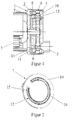
- Fig. 1 it can be seen in a schematic representation that the side channel pump 1 essentially from a housing 2, a drive 5 and a pump unit 6 is constructed.
- the pump unit 6 consists of a first side channel base body 7, a second side channel base body 8 and one arranged in between rotatable impeller 9, the liquid from an inlet 3 of the pumping station 6 promotes to an outlet 4 of the pump unit 6.
- the outlet 4 of the pumping station 6 is arranged in such a way that the pumped liquid flows around the drive 5 and thus additionally cools it.
- the side channel pump 1 shown here acts it is a two-stage pump, which can be seen on the two blade rings 10 and can see 11.
- the two side channel base bodies 7 and 8 each contain a side channel 12 or 13. With the help of the impeller 9 through the inlet 3rd of the pump unit 6 entering liquid through the liquid pulse brought higher pressure level and through the side channels 12 and 13 to the outlet guided.
- FIG. 2 shows a perspective view of one of the two side channel base bodies 7 or 8. It consists of a ceramic disc 14 and a plastic body 15, in this plan view of the plastic body 15 only the side channel 12 or 13 you can see.
- the ceramic disc 14 has a slot 16 which is approximately one Partial ring forms.
- the plastic body 15 forms the side channel 12 in this slot 16 or 13 off. In this version, the tapering of the cross section of the side channel 12 or 13 achieved by reducing its depth. It should be clear be that the manufacturing accuracy of the slot 16 is not particularly high needs because of inaccuracies due to the plastic body filling the slot 16 15 be balanced. That is why the efficiency of the side channel pump 1 the manufacturing accuracy of the side channels 12 and 13 relevant and not the Manufacturing accuracy of the slot 16.
- FIG. 3 shows the arrangement of plastic body 15 and ceramic in a side view Disc 14 shown. It can be clearly seen like the plastic body 15 forms the side channel 12 or 13 by its shape in the slot 16. This shape can be particularly easily during the injection molding Generate appropriately trained tools very precisely. In this version the tapering of the cross section of the side channel 12 or 13 by a reduction reached its depth. The cross section of the side channel 12 or 13 is in Fig. 3 on the right side significantly smaller than on the left side. The promotion of the liquid medium through the pump stage 6 is achieved by not shown Conveyor blades of the impeller 9 the side channel 12 or 13 in a known manner Paint over way.
- the impeller 9 and its conveyor blades are in direct contact with the surface 18 of the ceramic disc, it is for wear resistance crucial that the surface 18 is particularly smooth, for example by making the surface by honing or lapping. in the In contrast, the remaining surfaces of the ceramic disc 14 are rough to the connection between the ceramic disc 14 and the plastic body 15 additional support.
- the plastic body 15 encompasses in this embodiment the outer periphery of the ceramic disc 14 around the circumferential shoulder 17 and thus ensures that the ceramic disk 14 is fixed in the plastic body 15th
Landscapes
- Engineering & Computer Science (AREA)
- Mechanical Engineering (AREA)
- General Engineering & Computer Science (AREA)
- Structures Of Non-Positive Displacement Pumps (AREA)
Abstract
Description
Claims (8)
- Seitenkanalpumpe mit einem Gehäuse, einem Antrieb und mindestens einem Pumpenwerk, das Flüssigkeit vom Einlaß des Pumpenwerkes zum Auslaß des Pumpenwerkes fördert, wobei das Pumpenwerk zumindest einen ersten Seitenkanalgrundkörper, einen zweiten Seitenkanalgrundkörper und ein dazwischen angeordnetes drehbares Laufrad aufweist, wobei das Laufrad in beiden Axialwänden einen miteinander verbundenen Schaufelkranz und jeder Seitenkanalgrundkörper einen in Laufrichtung des Laufrades sich verjüngenden Seitenkanal aufweist, dadurch gekennzeichnet, dass der Seitenkanalgrundkörper (7 bzw. 8) aus dem Verbund einer keramischen Scheibe (14) und einen Kunststoffkörper (15) besteht, wobei die keramische Scheibe (14) einen Schlitz (16) enthält und im Schlitz (16) der Kunststoffkörper (15) die Form des Seitenkanals (12 bzw. 13) ausbildet.
- Seitenkanalpumpe nach Anspruch 1, dadurch gekennzeichnet, dass die keramische Scheibe (14) auf der dem Laufrad (9) zugewandten Seite am Umfang einen oder mehrere Absätz (17) aufweist und der Kunststoffkörper (15) die umlaufenden Absätze der keramischen Scheibe (17) ganz oder teilweise ausfüllt.
- Seitenkanalpumpe nach Anspruch 1 oder 2, dadurch gekennzeichnet, dass zumindest einer der Kunststoffkörper (15) integraler Bestandteil des Gehäuses (2) ist.
- Seitenkanalpumpe nach einem der Ansprüche 1 bis 3, dadurch gekennzeichnet, daß ein Einlaß (3) integraler Bestandteil des Kunststoffkörpers (7) ist.
- Keramische Scheibe für eine Seitenkanalpumpe nach einem der Ansprüche 1 bis 4, dadurch gekennzeichnet, dass die keramische Scheibe (14) auf der zum Laufrad (9) weisenden Fläche (18) glatt und auf allen anderen Flächen, insbesondere zu der dem Laufrad (9) abgewandten Seite, rau ist.
- Keramische Scheibe nach Anspruch 5, dadurch gekennzeichnet, dass die zum Pumpenrad (9) weisenden Fläche (18) durch Honen oder Läppen hergestellt ist.
- Kunststoffkörper für eine Seitenkanalpumpe nach einem der Ansprüche 1 bis 4, dadurch gekennzeichnet, dass der vom Kunststoffkörper (15) ausgebildete Seitenkanal (12 bzw. 13) seine Querschnittsverjüngung durch Verringerung der Breite und/oder Tiefe des Seitenkanals (12 bzw. 13) erfährt.
- Kunststoffkörper nach Anspruch 7, dadurch gekennzeichnet, dass der Kunststoffkörper (15) aus einem nicht im kraftstoffquellenden, formstabilen Kunststoff besteht.
Priority Applications (1)
| Application Number | Priority Date | Filing Date | Title |
|---|---|---|---|
| EP04026112A EP1503082B1 (de) | 2002-01-11 | 2002-09-10 | Seitenkanalgrundkörper für eine Seitenkanalpumpe |
Applications Claiming Priority (2)
| Application Number | Priority Date | Filing Date | Title |
|---|---|---|---|
| DE10200791A DE10200791A1 (de) | 2002-01-11 | 2002-01-11 | Seitenkanalpumpe |
| DE10200791 | 2002-01-11 |
Related Child Applications (1)
| Application Number | Title | Priority Date | Filing Date |
|---|---|---|---|
| EP04026112A Division EP1503082B1 (de) | 2002-01-11 | 2002-09-10 | Seitenkanalgrundkörper für eine Seitenkanalpumpe |
Publications (2)
| Publication Number | Publication Date |
|---|---|
| EP1329637A1 true EP1329637A1 (de) | 2003-07-23 |
| EP1329637B1 EP1329637B1 (de) | 2005-03-16 |
Family
ID=7711885
Family Applications (2)
| Application Number | Title | Priority Date | Filing Date |
|---|---|---|---|
| EP02020217A Expired - Lifetime EP1329637B1 (de) | 2002-01-11 | 2002-09-10 | Seitenkanalpumpe |
| EP04026112A Expired - Lifetime EP1503082B1 (de) | 2002-01-11 | 2002-09-10 | Seitenkanalgrundkörper für eine Seitenkanalpumpe |
Family Applications After (1)
| Application Number | Title | Priority Date | Filing Date |
|---|---|---|---|
| EP04026112A Expired - Lifetime EP1503082B1 (de) | 2002-01-11 | 2002-09-10 | Seitenkanalgrundkörper für eine Seitenkanalpumpe |
Country Status (3)
| Country | Link |
|---|---|
| US (1) | US6755610B2 (de) |
| EP (2) | EP1329637B1 (de) |
| DE (3) | DE10200791A1 (de) |
Families Citing this family (4)
| Publication number | Priority date | Publication date | Assignee | Title |
|---|---|---|---|---|
| DE10327321A1 (de) * | 2003-06-16 | 2005-01-13 | Siemens Ag | Als G-Rotorpumpe ausgebildete Verdrängerpumpe |
| JP4534677B2 (ja) * | 2003-10-31 | 2010-09-01 | 株式会社デンソー | 燃料ポンプ |
| RU2338884C1 (ru) * | 2007-01-18 | 2008-11-20 | Иван Иванович Пеньков | Роторно-вихревая машина с керамическими рабочими элементами |
| CN105782028A (zh) * | 2016-04-25 | 2016-07-20 | 域西机械技术(上海)有限公司 | 结构陶瓷在凸轮泵上的应用 |
Citations (3)
| Publication number | Priority date | Publication date | Assignee | Title |
|---|---|---|---|---|
| US5472321A (en) * | 1992-12-19 | 1995-12-05 | Pierburg Gmbh | Fuel pump having an impeller with axially balanced forces acting thereon |
| DE19704403A1 (de) * | 1997-02-06 | 1998-08-13 | Pierburg Ag | Brennstoffpumpe |
| US6095771A (en) * | 1995-12-30 | 2000-08-01 | Robert Bosch Gmbh | Fuel-feed unit |
Family Cites Families (2)
| Publication number | Priority date | Publication date | Assignee | Title |
|---|---|---|---|---|
| US6435810B1 (en) * | 2000-10-20 | 2002-08-20 | Delphi Technologies, Inc. | Wear resistant fuel pump |
| US6454521B1 (en) * | 2000-11-15 | 2002-09-24 | Delphi Technologies, Inc. | Wear resistant fuel pump |
-
2002
- 2002-01-11 DE DE10200791A patent/DE10200791A1/de not_active Withdrawn
- 2002-09-10 EP EP02020217A patent/EP1329637B1/de not_active Expired - Lifetime
- 2002-09-10 EP EP04026112A patent/EP1503082B1/de not_active Expired - Lifetime
- 2002-09-10 DE DE50205893T patent/DE50205893D1/de not_active Expired - Lifetime
- 2002-09-10 DE DE50202475T patent/DE50202475D1/de not_active Expired - Lifetime
- 2002-12-20 US US10/325,175 patent/US6755610B2/en not_active Expired - Fee Related
Patent Citations (3)
| Publication number | Priority date | Publication date | Assignee | Title |
|---|---|---|---|---|
| US5472321A (en) * | 1992-12-19 | 1995-12-05 | Pierburg Gmbh | Fuel pump having an impeller with axially balanced forces acting thereon |
| US6095771A (en) * | 1995-12-30 | 2000-08-01 | Robert Bosch Gmbh | Fuel-feed unit |
| DE19704403A1 (de) * | 1997-02-06 | 1998-08-13 | Pierburg Ag | Brennstoffpumpe |
Also Published As
| Publication number | Publication date |
|---|---|
| EP1503082B1 (de) | 2006-02-22 |
| DE50202475D1 (de) | 2005-04-21 |
| EP1503082A1 (de) | 2005-02-02 |
| DE10200791A1 (de) | 2003-07-24 |
| US6755610B2 (en) | 2004-06-29 |
| DE50205893D1 (de) | 2006-04-27 |
| EP1329637B1 (de) | 2005-03-16 |
| US20030133784A1 (en) | 2003-07-17 |
Similar Documents
| Publication | Publication Date | Title |
|---|---|---|
| DE1961299A1 (de) | Zusammengesetzte Riemenscheibe,beispielsweise fuer Lichtmaschinen in Kraftfahrzeugen,bestehend aus einem vorzugsweise auf dem Wege der spanlosen Formung hergestellten Scheibenteil mit Riemenrille aus Blech und mit Nabe sowie einem Luefterkranz | |
| DE2605546C3 (de) | Blasform zur Herstellung von Faltenbälgen aus Kunststoff | |
| AT506562A1 (de) | Zahnriemenrad | |
| WO2001069099A1 (de) | Aus einem band hergestelltes formteil | |
| WO2003064893A1 (de) | Anlaufscheibe eines planetengetriebes | |
| DE10334880A1 (de) | Anlaufscheibe für Planetengetriebe | |
| DE3821613C2 (de) | Kammkäfig für Kugellager | |
| EP0243718B1 (de) | Bauteil aus einem spritz- oder giessbaren polymeren Werkstoff | |
| DE102007055911A1 (de) | Rotationspumpe | |
| DE60102885T2 (de) | Verschleissbeständige Kraftstoffpumpe | |
| DE3016503A1 (de) | Waelzlager | |
| DE69702776T2 (de) | Ölpumpenrotor | |
| DE102013209922A1 (de) | Bundbuchse | |
| DE2653867A1 (de) | Hohlkolben und verfahren zu dessen herstellung | |
| DE3522020A1 (de) | Mehrteile steuerwelle fuer waermekraftmaschinen | |
| DE4332480C2 (de) | Hydraulisch dämpfendes Gummilager | |
| DE3720224C2 (de) | ||
| EP1329637B1 (de) | Seitenkanalpumpe | |
| DE3138005A1 (de) | Rohr fuer peristaltische pumpen | |
| DE29802228U1 (de) | Lagerschild | |
| DE102015013215A1 (de) | Mehrteiliges Hochleistungskettenrad | |
| DE3045192C2 (de) | Zahnradpumpe | |
| DE2262017B2 (de) | Vertikale, haengende kreiselpumpe | |
| DE2626445C3 (de) | Axial wirkende Gleitringdichtung, insbesondere für ölpumpen, mit einem Rückfördernuten aufweisenden Gleitring und Verfahren zur Herstellung des Gleitrings | |
| DE3601720A1 (de) | Freilauf |
Legal Events
| Date | Code | Title | Description |
|---|---|---|---|
| PUAI | Public reference made under article 153(3) epc to a published international application that has entered the european phase |
Free format text: ORIGINAL CODE: 0009012 |
|
| 17P | Request for examination filed |
Effective date: 20020910 |
|
| AK | Designated contracting states |
Designated state(s): AT BE BG CH CY CZ DE DK EE ES FI FR GB GR IE IT LI LU MC NL PT SE SK TR |
|
| AX | Request for extension of the european patent |
Extension state: AL LT LV MK RO SI |
|
| RAP1 | Party data changed (applicant data changed or rights of an application transferred) |
Owner name: TI AUTOMOTIVE (NEUSS) GMBH |
|
| 17Q | First examination report despatched |
Effective date: 20040116 |
|
| AKX | Designation fees paid |
Designated state(s): DE ES FR GB IT |
|
| GRAP | Despatch of communication of intention to grant a patent |
Free format text: ORIGINAL CODE: EPIDOSNIGR1 |
|
| GRAA | (expected) grant |
Free format text: ORIGINAL CODE: 0009210 |
|
| GRAS | Grant fee paid |
Free format text: ORIGINAL CODE: EPIDOSNIGR3 |
|
| AK | Designated contracting states |
Kind code of ref document: B1 Designated state(s): DE ES FR GB IT |
|
| PG25 | Lapsed in a contracting state [announced via postgrant information from national office to epo] |
Ref country code: IT Free format text: LAPSE BECAUSE OF FAILURE TO SUBMIT A TRANSLATION OF THE DESCRIPTION OR TO PAY THE FEE WITHIN THE PRESCRIBED TIME-LIMIT;WARNING: LAPSES OF ITALIAN PATENTS WITH EFFECTIVE DATE BEFORE 2007 MAY HAVE OCCURRED AT ANY TIME BEFORE 2007. THE CORRECT EFFECTIVE DATE MAY BE DIFFERENT FROM THE ONE RECORDED. Effective date: 20050316 Ref country code: GB Free format text: LAPSE BECAUSE OF FAILURE TO SUBMIT A TRANSLATION OF THE DESCRIPTION OR TO PAY THE FEE WITHIN THE PRESCRIBED TIME-LIMIT Effective date: 20050316 |
|
| REG | Reference to a national code |
Ref country code: GB Ref legal event code: FG4D Free format text: NOT ENGLISH |
|
| REF | Corresponds to: |
Ref document number: 50202475 Country of ref document: DE Date of ref document: 20050421 Kind code of ref document: P |
|
| PG25 | Lapsed in a contracting state [announced via postgrant information from national office to epo] |
Ref country code: ES Free format text: LAPSE BECAUSE OF FAILURE TO SUBMIT A TRANSLATION OF THE DESCRIPTION OR TO PAY THE FEE WITHIN THE PRESCRIBED TIME-LIMIT Effective date: 20050627 |
|
| GBV | Gb: ep patent (uk) treated as always having been void in accordance with gb section 77(7)/1977 [no translation filed] |
Effective date: 20050316 |
|
| ET | Fr: translation filed | ||
| PLBE | No opposition filed within time limit |
Free format text: ORIGINAL CODE: 0009261 |
|
| STAA | Information on the status of an ep patent application or granted ep patent |
Free format text: STATUS: NO OPPOSITION FILED WITHIN TIME LIMIT |
|
| 26N | No opposition filed |
Effective date: 20051219 |
|
| PGFP | Annual fee paid to national office [announced via postgrant information from national office to epo] |
Ref country code: DE Payment date: 20100929 Year of fee payment: 9 |
|
| PGFP | Annual fee paid to national office [announced via postgrant information from national office to epo] |
Ref country code: FR Payment date: 20111005 Year of fee payment: 10 |
|
| REG | Reference to a national code |
Ref country code: FR Ref legal event code: ST Effective date: 20130531 |
|
| PG25 | Lapsed in a contracting state [announced via postgrant information from national office to epo] |
Ref country code: DE Free format text: LAPSE BECAUSE OF NON-PAYMENT OF DUE FEES Effective date: 20130403 |
|
| PG25 | Lapsed in a contracting state [announced via postgrant information from national office to epo] |
Ref country code: FR Free format text: LAPSE BECAUSE OF NON-PAYMENT OF DUE FEES Effective date: 20121001 |
|
| REG | Reference to a national code |
Ref country code: DE Ref legal event code: R119 Ref document number: 50202475 Country of ref document: DE Effective date: 20130403 |