EP1329375A2 - Upper connecting structure of center pillar for automobile - Google Patents
Upper connecting structure of center pillar for automobile Download PDFInfo
- Publication number
- EP1329375A2 EP1329375A2 EP03250360A EP03250360A EP1329375A2 EP 1329375 A2 EP1329375 A2 EP 1329375A2 EP 03250360 A EP03250360 A EP 03250360A EP 03250360 A EP03250360 A EP 03250360A EP 1329375 A2 EP1329375 A2 EP 1329375A2
- Authority
- EP
- European Patent Office
- Prior art keywords
- side rail
- center pillar
- connecting structure
- vehicle
- rail outer
- Prior art date
- Legal status (The legal status is an assumption and is not a legal conclusion. Google has not performed a legal analysis and makes no representation as to the accuracy of the status listed.)
- Granted
Links
- 239000011324 bead Substances 0.000 claims description 29
- 230000002787 reinforcement Effects 0.000 claims description 22
- 238000003466 welding Methods 0.000 claims description 9
- 229910000831 Steel Inorganic materials 0.000 description 4
- 239000010959 steel Substances 0.000 description 4
- 238000006073 displacement reaction Methods 0.000 description 3
- 238000010276 construction Methods 0.000 description 2
- 239000000463 material Substances 0.000 description 2
- 239000000470 constituent Substances 0.000 description 1
- 239000006185 dispersion Substances 0.000 description 1
- 230000000694 effects Effects 0.000 description 1
- 238000000465 moulding Methods 0.000 description 1
Images



Classifications
-
- B—PERFORMING OPERATIONS; TRANSPORTING
- B62—LAND VEHICLES FOR TRAVELLING OTHERWISE THAN ON RAILS
- B62D—MOTOR VEHICLES; TRAILERS
- B62D25/00—Superstructure or monocoque structure sub-units; Parts or details thereof not otherwise provided for
- B62D25/06—Fixed roofs
Definitions
- the present invention relates to a body structure for a vehicle and more particularly to a connecting structure of an upper part of a center pillar of the vehicle.
- Japanese Patent Application No. Toku-Kai-Hei 11-348821 proposes a connecting structure constituted by a panel side outer integrally formed with a center pillar outer and a side rail outer, a side rail inner, a center pillar inner and a reinforcement.
- a connecting structure of a center pillar with a side rail there is a connecting structure shown in a perspective view of Fig. 7 showing an upper connecting portion of a center pillar and in a sectional view of Fig. 8 taken along a line VIII-VIII of Fig. 7.
- This connecting structure of the center pillar comprises a side rail, a center pillar and a reinforcement disposed in the center pillar. That is, a side rail 50 provided outside of a vehicle body has a closed cross section formed by a side rail outer 52 extending in a longitudinal direction of a vehicle and a side rail inner 54 disposed inside of the side rail outer 52 and extending in a longitudinal direction of the vehicle.
- the center pillar 56 is constituted by a center pillar outer 62 and a center pillar inner 64.
- the center pillar outer 62 is bent outwardly at the upper portion thereof along the outer shape of the side rail outer 52 and is superposed on the outer surface of the side rail outer 52.
- Reference numeral 66 of Fig. 8 denotes a drip rail and reference numeral 68 denotes a roof panel.
- FIG. 9 shows still another example of the upper connecting structure of a center pillar.
- the upper connecting structure of the center pillar shown in Fig. 7 (or Fig. 8) and that shown in Fig. 9 in providing a center pillar outer reinforcement 70 inside of the center pillar outer 62 and providing a welding surface 72 (shown in a two-dots chain line of Fig. 7) in the side rail outer 52. That is, the top portion of the center pillar outer reinforcement 70 is interposed into the side rail constituted by the side rail outer 52 and the side rail inner 54 and is welded at the upper portion thereof to the back surface of the side rail outer 52.
- the aforesaid upper connecting structure of the center pillar has a problem that the connecting portion of the center pillar with the side rail is easily broken when a big load is exerted from the lateral side of a vehicle in the case of a side-on collision and the like. Accordingly, in order to increase the strength of the connecting portion of the center pillar with the side rail, there are countermeasures such as using plate material with large thickness for the constituents of the side rail, center pillar and the like, adding reinforcements thereto et cetera.
- an upper connecting structure of a center pillar of a vehicle for connecting said center pillar with a side rail comprises a ridge line formed on the side rail outer and extending in a longitudinal direction of the vehicle and a plurality of bead sections formed on the side rail outer and provided across the ridge line in the vicinity of a connecting portion of the side rail outer with the center pillar.
- the bead sections are preferably formed with the connecting portion of the side rail outer and the center pillar between.
- reference numeral 10 denotes a side rail disposed at an upper portion of a lateral side of a vehicle body and the side rail 10 is a closed cross section channel constituted by a side rail outer 12 disposed outside of a vehicle body and a side rail inner 14 disposed inside of the vehicle body.
- the side rail outer 12 is a member extending in a longitudinal direction of the vehicle and has a C-shaped cross section successively formed by an upper surface 12a, a side surface 12b and a lower surface 12c and an upper flange 13a is formed at the upper edge of the upper surface 12a.
- a concave section 12d is formed at the lower edge of the lower surface 12c.
- the upper section of the center pillar outer 16 is superposed on the concave section 12d to the shape the center pillar outer 16.
- a ridge line R is formed between the upper surface 12a and the side surface 12b of the side rail outer 12 in a longitudinal direction of the vehicle. Further, a plurality of bead sections 12e are formed across the ridge line R over the upper surface 12a and the side surface 12b in a lateral direction of the vehicle. As understood from Fig. 1, the bead sections 12e are formed in the vicinity of the connecting section of the side rail outer 12 with the center pillar 20. In this embodiment, a pair of bead sections 12e are formed with the connecting section of the side rail outer 12 with the center pillar 20 between.
- the side rail inner 14 is a member extending in a longitudinal direction of the vehicle andhas a U-shaped or C-shaped cross section successively formed by an upper surface 14a, a side surface 14b and a lower surface 14c and an upper flange 15a is formed at the upper edge of the upper surface 14a in an opposed manner to the upper flange 13a of the side rail outer 12. Further, a lower flange 15b is formed at the lower edge of the lower surface 14c in an opposed manner to the lower flange 13b.
- the center pillar outer 16 has a U-shaped or C-shaped cross section and is formed at the upper section thereof into a T-shape in a longitudinal direction of the vehicle,
- the T-shape section of the center pillar outer 16 has a side rail connecting surface 16a and an upper end flange 17a opposite to the lower surface 12c and the side surface 12b of the side rail 12, respectively.
- the center pillar outer 16 includes a front flange 17b connected with the lower edge of the side rail connecting surface 16a and a rear flange 17c connected with the lower edge of the side rail connecting surface 16a.
- the center pillar inner 18 has a U-shaped cross section and includes a front flange 19a and a rear flange (not shown) opposite to the front flange 17b and the rear flange 17c of the center pillar outer 16, respectively. Further, the center pillar inner 18 has an upper end flange 19c opposite to the side surface 14b of the side rail inner 14 at the upper portion thereof.
- the center pillar outer 16 is superposed on a lower flange 13b formed at a concave portion 12d of the side rail outer 12 and the connecting surface of the center pillar outer 16 is superposed on the connecting surface of the side rail outer 12. Further, thus superposed side rail outer 12 and center pillar outer 16 are welded to each other and as a result the side rail outer 12 is integrally connected with the center pillar outer 16.
- the upper flange 13a of the side rail outer 12 is superposed on and welded to the upper flange 15a of the side rail inner 14 and the lower flange 13b of the side rail outer 12 is superposed on the lower flange 15b of the side rail inner 14.
- the lower flange 13b is superposed on and welded to the front flange 17b formed at the lower edge of the side rail connecting surface 16a of the center pillar outer 16 and the lower flange 15b is superposed on and welded to the upper portion of the rear flange 17c.
- a drip rail 21 is superposed on and welded to the upper flange 17a of the center pillar outer 16 and a side end flange 22a of a roof panel 22 is superposed on and welded to the drip rail 21.
- the front flange 17b of the center pillar outer 16 is superposed on and welded to the front flange 19a of the center pillar inner 18 and the rear flange 17c of the center pillar outer 16 is superposed on and welded to the rear flange of the center pillar inner 18.
- the side rail 10 having a closed cross section is formed by the side rail outer 12 and the side rail inner 14 and the center pillar 20 having a closed cross section is formed by the center pillar outer 16 and the center pillar inner 18.
- the load is transferredtothe side rail outer 12, particularly to the plurality of the bead sections 12e formed on the side rail outer 12, whereby the load transferred to the side rail outer 12 through the center pillar 20 is dispersed and as a result the collapse of the connecting portion of the side rail 10 with the center pillar 20 can be prevented
- the load diverges in front and rear directions of the vehicle.
- the bead sections 12e keep the configuration of the side rail outer 12.
- the bead sections 12e for dispersing the load retain the configuration of the side rail outer 12
- Fig. 3 is a graph showing the result of a confirmatory testing of the effect of the load dispersion in the upper connecting structure of the center pillar according to the present invention.
- the ordinate axis is a displacement of a side rail into a vehicle body in the event of a side-on collision and the abscissa axis is elapsed time.
- the test result according to the first embodiment of the present invention is charted in a solid line and the test result of an example according to the prior art shown in Fig. 7 is charted in a broken line.
- the displacement of the side rail into the vehicle body is improved by around 10 %.
- the second embodiment is different from the first embodiment in having a center pillar outer reinforcement 23 in place of the center pillar 16 and further having an outside panel 25 outside of the center pillar outer reinforcement 23.
- An upper end flange 25a of the outside panel 25 is welded to the side end flange 22a of the roof panel 22 and to the upper flange 13a of the side rail outer 12 in interleaving relation to both and further the upper flange 13a is welded to the upper flange 15a of the side rail inner 14 from underneath.
- the bead sections 12e act to efficiently disperse a load transferred to the side rail outer 12 from the center pillar 20, whereby the connecting portion of the side rail 10 with the center pillar 20 can be prevented from being broken due to a load concentration.
- the upper connecting structure of the center pillar according to the third embodiment differs from that according to the first embodiment in further having a center pillar outer reinforcement 27 rigidly connected with the inner surface of the side rail outer 12.
- the center pillar outer reinforcement 27 is molded to the inner surface of the center pillar outer 16 and has an upper end flange 27a at the upper portion thereof opposite to the inner surface of the bead sections 12e formed in the side rail outer 12.
- the upper end flange 27a of the center pillar outer reinforcement 27 is rigidly connected to the bead sections 12e formed in the side rail outer 12.
- the position of the upper end flange 27a to be welded to the bead sections 12e is marked with "x".
- the bead section 12e serves to efficiently disperse a load transferred to the side rail outer 12 from the center pillar 20, whereby the connecting portion of the side rail 10 with the center pillar 20 can be prevented from being broken due to a load concentration
- the bead section 12e serves as a welding surface where the side rail outer 12 is welded to the center pillar outer reinforcement 27. Hence, it is not necessary to provide a special welding surface where the side rail outer 12 is welded to the center pillar outer reinforcement 27.
- the upper connecting structure of the center pillar according to the fourth embodiment differs from that according to the first embodiment in further having a side rail reinforcement 29 connected with the inner surface of the side rail outer 12.
- the side rail reinforcement 29 is molded to the inner surface of the side rail outer 12 and has an upper end flange 29a being opposite to the inner surface of the bead section 12e formed in the side rail outer 12 in the upper portion thereof and a lower end flange 29b being opposite to the inner surface of the lower surface 12c of the side rail outer 12 in the lower portion thereof.
- the upper end flange 29a of the side rail reinforcement 29 is superposed on and welded to the bead section 12e formed in the side rail outer 12.
- the lower end flange 29b of the side rail reinforcement 29 is superposed on from underneath and welded to the lower surface 12c formed in the side rail outer 12.
- a mark "x" of Fig. 6 indicates a position where the bead section 12e is welded to the upper end flange 29a.
- the bead section 12e serves to efficiently disperse a load transfered to the side rail outer 12 from the center pillar 20, whereby the connecting portion of the side rail 10 with the center pillar 20 can be prevented from being broken due to a load concenteation
- the bead section 12e serves as a welding surface where the side rail outer 12 is welded to the side rail reinforcement 29. Hence, it is not necessary to provide a special welding surface where the side rail outer 12 is welded to the side rail reinforcement 29.
Landscapes
- Engineering & Computer Science (AREA)
- Chemical & Material Sciences (AREA)
- Combustion & Propulsion (AREA)
- Transportation (AREA)
- Mechanical Engineering (AREA)
- Body Structure For Vehicles (AREA)
Abstract
Description
- The present invention relates to a body structure for a vehicle and more particularly to a connecting structure of an upper part of a center pillar of the vehicle.
- With respect to a body structure for connecting a center pillar with a side rail of a vehicle, Japanese Patent Application No. Toku-Kai-Hei 11-348821 proposes a connecting structure constituted by a panel side outer integrally formed with a center pillar outer and a side rail outer, a side rail inner, a center pillar inner and a reinforcement.
- Further, with respect to another connecting structure of a center pillar with a side rail, there is a connecting structure shown in a perspective view of Fig. 7 showing an upper connecting portion of a center pillar and in a sectional view of Fig. 8 taken along a line VIII-VIII of Fig. 7. This connecting structure of the center pillar comprises a side rail, a center pillar and a reinforcement disposed in the center pillar. That is, a
side rail 50 provided outside of a vehicle body has a closed cross section formed by a side rail outer 52 extending in a longitudinal direction of a vehicle and a side rail inner 54 disposed inside of the side rail outer 52 and extending in a longitudinal direction of the vehicle. - The
center pillar 56 is constituted by a center pillar outer 62 and a center pillar inner 64. The center pillar outer 62 is bent outwardly at the upper portion thereof along the outer shape of the side rail outer 52 and is superposed on the outer surface of the side rail outer 52.Reference numeral 66 of Fig. 8 denotes a drip rail andreference numeral 68 denotes a roof panel. - Further, Fig. 9 shows still another example of the upper connecting structure of a center pillar. There are differences between the upper connecting structure of the center pillar shown in Fig. 7 (or Fig. 8) and that shown in Fig. 9 in providing a center pillar
outer reinforcement 70 inside of the center pillar outer 62 and providing a welding surface 72 (shown in a two-dots chain line of Fig. 7) in the side rail outer 52. That is, the top portion of the center pillarouter reinforcement 70 is interposed into the side rail constituted by the side rail outer 52 and the side rail inner 54 and is welded at the upper portion thereof to the back surface of the side rail outer 52. - However, the aforesaid upper connecting structure of the center pillar has a problem that the connecting portion of the center pillar with the side rail is easily broken when a big load is exerted from the lateral side of a vehicle in the case of a side-on collision and the like. Accordingly, in order to increase the strength of the connecting portion of the center pillar with the side rail, there are countermeasures such as using plate material with large thickness for the constituents of the side rail, center pillar and the like, adding reinforcements thereto et cetera.
- However, using steel plates with large thickness for the center pillar, side rail and the like causes bad weldability, weight increase and cost increase. Further, additional reinforcements require an establishment of new welding surfaces and the welding surfaces themselves have a possibility of providing starting points of breakage, depending upon the position and configuration of the reinforcements. Further, in the case where high tension steel plates are used for material of the side rail and the like, it is necessary to fix bent edges of the high tension steel plates by beads in order to prevent spring back phenomena after molding. In this case, sometimes the beads themselves become starting points from which breakage of the side rail starts.
- It is an object of the present invention to provide an upper connecting structure of a center pillar having a large rigidity and capable of efficiently dispersing a load exerted on the center pillar from the lateral side of a vehicle to a side rail.
- In order to attain the object, an upper connecting structure of a center pillar of a vehicle for connecting said center pillar with a side rail comprises a ridge line formed on the side rail outer and extending in a longitudinal direction of the vehicle and a plurality of bead sections formed on the side rail outer and provided across the ridge line in the vicinity of a connecting portion of the side rail outer with the center pillar.
- The bead sections are preferably formed with the connecting portion of the side rail outer and the center pillar between.
- By way of example only, specific embodiments of the present invention will now be described, with reference to the accompanying drawings, in which:-
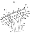
- Fig. 1 is a perspective view showing a connectingportion of a center pillar with a side rail for a vehicle according to a first embodiment of the present invention;
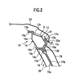
- Fig. 2 is a sectional view taken along a line II-II of Fig. 1;
- Fig. 3 is a graph showing a time versus displacement of a side rail according to the upper connecting structure of the center pillar of the present invention in an event of a side-on impact;
- Fig. 4 is a sectional view of a connecting portion of a center pillar with a side rail according to a second embodiment of the present invention;
- Fig. 5 is a sectional view of a connecting portion of a center pillar with a side rail according to a third embodiment of the present invention;
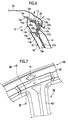
- Fig. 6 is a sectional view of a connecting portion of a center pillar with a side rail according to a fourth embodiment of the present invention;
- Fig. 7 is a perspective view showing an upper connecting structure of a center pillar for a vehicle according to a prior art construction;
- Fig. 8 is a sectional view taken along a line VII-VII of Fig. 7; and
- Fig. 9 is a sectional view showing another example of an upper connecting structure of a center pillar for a vehicle according to a prior art construction.
-
- Referring now to Fig. 1 and Fig. 2,
reference numeral 10 denotes a side rail disposed at an upper portion of a lateral side of a vehicle body and theside rail 10 is a closed cross section channel constituted by a side rail outer 12 disposed outside of a vehicle body and a side rail inner 14 disposed inside of the vehicle body. - The side rail outer 12 is a member extending in a longitudinal direction of the vehicle and has a C-shaped cross section successively formed by an
upper surface 12a, aside surface 12b and alower surface 12c and anupper flange 13a is formed at the upper edge of theupper surface 12a. On the other hand, aconcave section 12d is formed at the lower edge of thelower surface 12c. Further, the upper section of the center pillar outer 16 is superposed on theconcave section 12d to the shape the center pillar outer 16. - A ridge line R is formed between the
upper surface 12a and theside surface 12b of the side rail outer 12 in a longitudinal direction of the vehicle. Further, a plurality ofbead sections 12e are formed across the ridge line R over theupper surface 12a and theside surface 12b in a lateral direction of the vehicle. As understood from Fig. 1, thebead sections 12e are formed in the vicinity of the connecting section of the side rail outer 12 with thecenter pillar 20. In this embodiment, a pair ofbead sections 12e are formed with the connecting section of the side rail outer 12 with thecenter pillar 20 between. - The side rail inner 14 is a member extending in a longitudinal direction of the vehicle andhas a U-shaped or C-shaped cross section successively formed by an
upper surface 14a, aside surface 14b and alower surface 14c and anupper flange 15a is formed at the upper edge of theupper surface 14a in an opposed manner to theupper flange 13a of the side rail outer 12. Further, alower flange 15b is formed at the lower edge of thelower surface 14c in an opposed manner to thelower flange 13b. - The center pillar outer 16 has a U-shaped or C-shaped cross section and is formed at the upper section thereof into a T-shape in a longitudinal direction of the vehicle, The T-shape section of the center pillar outer 16 has a side
rail connecting surface 16a and anupper end flange 17a opposite to thelower surface 12c and theside surface 12b of theside rail 12, respectively. Further, the center pillar outer 16 includes afront flange 17b connected with the lower edge of the siderail connecting surface 16a and arear flange 17c connected with the lower edge of the siderail connecting surface 16a. - The center pillar inner 18 has a U-shaped cross section and includes a
front flange 19a and a rear flange (not shown) opposite to thefront flange 17b and therear flange 17c of the center pillar outer 16, respectively. Further, the center pillar inner 18 has anupper end flange 19c opposite to theside surface 14b of the side rail inner 14 at the upper portion thereof. - Thus formed
upper end flange 19c of the center pillar inner 18 is superposed on and welded to theside surface 14b of the side rail inner 14, the side rail inner 14 being integrally connected with the center pillar inner 18. - On the other hand, the center pillar outer 16 is superposed on a
lower flange 13b formed at aconcave portion 12d of the side rail outer 12 and the connecting surface of the center pillar outer 16 is superposed on the connecting surface of the side rail outer 12. Further, thus superposed side rail outer 12 and center pillar outer 16 are welded to each other and as a result the side rail outer 12 is integrally connected with the center pillar outer 16. - Further, the
upper flange 13a of the side rail outer 12 is superposed on and welded to theupper flange 15a of the side rail inner 14 and thelower flange 13b of the side rail outer 12 is superposed on thelower flange 15b of the side rail inner 14. Further, thelower flange 13b is superposed on and welded to thefront flange 17b formed at the lower edge of the siderail connecting surface 16a of the center pillar outer 16 and thelower flange 15b is superposed on and welded to the upper portion of therear flange 17c. Further, a drip rail 21 is superposed on and welded to theupper flange 17a of the center pillar outer 16 and aside end flange 22a of aroof panel 22 is superposed on and welded to the drip rail 21. - Similarly, the
front flange 17b of the center pillar outer 16 is superposed on and welded to thefront flange 19a of the center pillar inner 18 and therear flange 17c of the center pillar outer 16 is superposed on and welded to the rear flange of the center pillar inner 18. - Thus, the
side rail 10 having a closed cross section is formed by the side rail outer 12 and the side rail inner 14 and thecenter pillar 20 having a closed cross section is formed by the center pillar outer 16 and the center pillar inner 18. - According to the first embodiment, in the case where a load is applied to the lateral side of the vehicle, the load is transferredtothe side rail outer 12, particularly to the plurality of the
bead sections 12e formed on the side rail outer 12, whereby the load transferred to the side rail outer 12 through thecenter pillar 20 is dispersed and as a result the collapse of the connecting portion of theside rail 10 with thecenter pillar 20 can be prevented In the first emboidment, since thebead sections 12e are formed in a longitudinal direction of the vehicle with the connecting portion of theside rail 10 and thecenter pillar 20 between, the load diverges in front and rear directions of the vehicle. - Further, according to the first embodiment, the
bead sections 12e keep the configuration of the side rail outer 12. In the case where high tension steel plates are used for the side rail outer 12, it is necessary to provide additional beads in the side rail outer 12 in order to retain the configuration of the side rail outer 12. However, since thebead sections 12e for dispersing the load retain the configuration of the side rail outer 12, it is not necessary to provide additional beads in order to retain the configuration of theside rail 12. Accordingly. these additional beads can be prevented from becoming starting points from which breakage of the side rail starts. - Fig. 3 is a graph showing the result of a confirmatory testing of the effect of the load dispersion in the upper connecting structure of the center pillar according to the present invention. In the graph, the ordinate axis is a displacement of a side rail into a vehicle body in the event of a side-on collision and the abscissa axis is elapsed time. The test result according to the first embodiment of the present invention is charted in a solid line and the test result of an example according to the prior art shown in Fig. 7 is charted in a broken line. As understood from Fig. 3, the displacement of the side rail into the vehicle body is improved by around 10 %.
- Next, an upper connecting structure of the center pillar according to a second embodiment of the present invention will be described by reference to Fig. 4.
- The second embodiment is different from the first embodiment in having a center pillar
outer reinforcement 23 in place of thecenter pillar 16 and further having anoutside panel 25 outside of the center pillarouter reinforcement 23. Anupper end flange 25a of theoutside panel 25 is welded to theside end flange 22a of theroof panel 22 and to theupper flange 13a of the side rail outer 12 in interleaving relation to both and further theupper flange 13a is welded to theupper flange 15a of the side rail inner 14 from underneath. - In a similar way to the first embodiment, the
bead sections 12e act to efficiently disperse a load transferred to the side rail outer 12 from thecenter pillar 20, whereby the connecting portion of theside rail 10 with thecenter pillar 20 can be prevented from being broken due to a load concentration. - Next, an upper connecting structure of the center pillar according to a third embodiment of the present invention will be described by reference to Fig. 5.
- The upper connecting structure of the center pillar according to the third embodiment differs from that according to the first embodiment in further having a center pillar
outer reinforcement 27 rigidly connected with the inner surface of the side rail outer 12. The center pillarouter reinforcement 27 is molded to the inner surface of the center pillar outer 16 and has anupper end flange 27a at the upper portion thereof opposite to the inner surface of thebead sections 12e formed in the side rail outer 12. Theupper end flange 27a of the center pillarouter reinforcement 27 is rigidly connected to thebead sections 12e formed in the side rail outer 12. In the drawing, the position of theupper end flange 27a to be welded to thebead sections 12e is marked with "x". - Also in the case of the third embodiment, the
bead section 12e serves to efficiently disperse a load transferred to the side rail outer 12 from thecenter pillar 20, whereby the connecting portion of theside rail 10 with thecenter pillar 20 can be prevented from being broken due to a load concentration, - Further, in the third embodiment, the
bead section 12e serves as a welding surface where the side rail outer 12 is welded to the center pillarouter reinforcement 27. Hence, it is not necessary to provide a special welding surface where the side rail outer 12 is welded to the center pillarouter reinforcement 27. - Next, an upper connecting structure of the center pillar according to a fourth embodiment of the present invention will be described by reference to Fig. 6.
- The upper connecting structure of the center pillar according to the fourth embodiment differs from that according to the first embodiment in further having a
side rail reinforcement 29 connected with the inner surface of the side rail outer 12. Theside rail reinforcement 29 is molded to the inner surface of the side rail outer 12 and has anupper end flange 29a being opposite to the inner surface of thebead section 12e formed in the side rail outer 12 in the upper portion thereof and alower end flange 29b being opposite to the inner surface of thelower surface 12c of the side rail outer 12 in the lower portion thereof. Theupper end flange 29a of theside rail reinforcement 29 is superposed on and welded to thebead section 12e formed in the side rail outer 12. Further, thelower end flange 29b of theside rail reinforcement 29 is superposed on from underneath and welded to thelower surface 12c formed in the side rail outer 12. A mark "x" of Fig. 6 indicates a position where thebead section 12e is welded to theupper end flange 29a. - Also in the case of the fourth embodiment, the
bead section 12e serves to efficiently disperse a load transfered to the side rail outer 12 from thecenter pillar 20, whereby the connecting portion of theside rail 10 with thecenter pillar 20 can be prevented from being broken due to a load concenteation - Further, in the fourth embodiment, the
bead section 12e serves as a welding surface where the side rail outer 12 is welded to theside rail reinforcement 29. Hence, it is not necessary to provide a special welding surface where the side rail outer 12 is welded to theside rail reinforcement 29. - The entire contents of Japanese Patent Application No Tokugan 2002-013288 filed January 22, 2002, is incorporated herein by reference.
- While the present invention has been disclosed in terms of the preferred embodiments in order to facilitate better understanding of the invention, it should be appreciated that the invention can be embodied in various ways without departing from the principle of the invention. Therefore, the invention should be understood to include all possible embodiments which can be embodied without departing from the scope of the invention.
Claims (6)
- An upper connecting structure of a center pillar of a vehicle for connecting said center pillar with a side rail constituted by a side rail outer and a side rail inner, comprising:a ridge line formed on said side rail outer and extending in a longitudinal direction of said vehicle; anda plurality of bead sections formed on said side rail outer and provided across said ridge line in the vicinity of a connecting portion of said side rail outer and said center pillar.
- The upper connecting structure of said center pillar according to claim 1, wherein said bead sections are formed with said connecting portion between.
- The upper connecting structure of said center pillar according to claim 1 or claim 2, further comprising
a reinforcement connected with an inner surface of said side rail outer; and
a welding surface constituted by said bead section for welding said side rail outer to said reinforcement. - The upper connecting structure of said center pillar according to any of claims 1 to 3, wherein said bead section retains the configuration of said side rail outer.
- A center pillar of a vehicle comprising the upper connecting structure as claimed in any of claims 1 to 4.
- A vehicle comprising a center pillar as claimed in claim 5.
Applications Claiming Priority (2)
| Application Number | Priority Date | Filing Date | Title |
|---|---|---|---|
| JP2002013288A JP4145052B2 (en) | 2002-01-22 | 2002-01-22 | Automobile center pillar upper coupling structure |
| JP2002013288 | 2002-01-22 |
Publications (3)
| Publication Number | Publication Date |
|---|---|
| EP1329375A2 true EP1329375A2 (en) | 2003-07-23 |
| EP1329375A3 EP1329375A3 (en) | 2003-08-27 |
| EP1329375B1 EP1329375B1 (en) | 2007-05-16 |
Family
ID=19191801
Family Applications (1)
| Application Number | Title | Priority Date | Filing Date |
|---|---|---|---|
| EP03250360A Expired - Lifetime EP1329375B1 (en) | 2002-01-22 | 2003-01-21 | Upper connecting structure of center pillar for automobile |
Country Status (4)
| Country | Link |
|---|---|
| US (1) | US6789840B2 (en) |
| EP (1) | EP1329375B1 (en) |
| JP (1) | JP4145052B2 (en) |
| DE (1) | DE60313815T2 (en) |
Cited By (5)
| Publication number | Priority date | Publication date | Assignee | Title |
|---|---|---|---|---|
| CN1329236C (en) * | 2003-10-20 | 2007-08-01 | 三菱自动车工业株式会社 | Coupling structure of vehicle body parts |
| WO2009037537A1 (en) | 2007-09-21 | 2009-03-26 | Toyota Jidosha Kabushiki Kaisha | Formed part for vehicle body structural member |
| EP2669148A4 (en) * | 2011-01-26 | 2014-08-20 | Toyota Motor Co Ltd | COUPLING STRUCTURE OF UPPER PART OF CENTRAL AMOUNT |
| CN104903181A (en) * | 2012-11-15 | 2015-09-09 | 五十铃自动车株式会社 | Roof structure of vehicle |
| CN105377675A (en) * | 2012-10-15 | 2016-03-02 | 马自达汽车株式会社 | Joint structure for members of different kinds of metal |
Families Citing this family (22)
| Publication number | Priority date | Publication date | Assignee | Title |
|---|---|---|---|---|
| JP4093104B2 (en) * | 2003-04-22 | 2008-06-04 | 日産自動車株式会社 | Auto body structure |
| US6976730B2 (en) * | 2004-03-26 | 2005-12-20 | Nissan Technical Center North America, Inc. | Vehicle body structure |
| JP4465599B2 (en) * | 2004-09-10 | 2010-05-19 | スズキ株式会社 | Joint structure at the top of the center pillar |
| JP2006088924A (en) * | 2004-09-24 | 2006-04-06 | Mitsubishi Automob Eng Co Ltd | Body structure |
| US7293823B2 (en) * | 2005-11-16 | 2007-11-13 | Ford Global Technologies, Llc | Interlocked pillar and roof rail joint |
| DE102007042277B4 (en) * | 2007-09-06 | 2010-07-08 | Thyssenkrupp Drauz Nothelfer Gmbh | Roof construction of a vehicle body |
| JP5407372B2 (en) * | 2009-01-30 | 2014-02-05 | マツダ株式会社 | Vehicle side body structure |
| CN102216146B (en) * | 2009-03-02 | 2012-12-05 | 丰田自动车株式会社 | Skelton structure of vehicle |
| JP5018973B2 (en) * | 2009-04-03 | 2012-09-05 | トヨタ自動車株式会社 | Body structure |
| US9085327B2 (en) * | 2009-06-10 | 2015-07-21 | Ford Global Technologies, Llc | Vehicle roof reinforcement |
| US8690231B2 (en) | 2009-06-18 | 2014-04-08 | Toyota Jidosha Kabushiki Kaisha | Vehicle structure body |
| JP5714967B2 (en) * | 2011-04-13 | 2015-05-07 | 富士重工業株式会社 | Body shock absorbing structure |
| DE102011101551A1 (en) * | 2011-05-14 | 2012-11-15 | Volkswagen Aktiengesellschaft | Roof frame structure for vehicle, has rail-side roof, which has hollow profile that is defined by lateral parts of rail-side roof, where lateral parts are connected with each other by flange connection |
| US9156505B2 (en) | 2011-11-16 | 2015-10-13 | Toyota Jidosha Kabushiki Kaisha | Structure for joining center pillar and roof side rail |
| JP6066317B2 (en) | 2013-05-24 | 2017-01-25 | スズキ株式会社 | Joining structure of pillar and lower part of roof in vehicle |
| JP6135699B2 (en) * | 2015-03-11 | 2017-05-31 | トヨタ自動車株式会社 | Vehicle side structure |
| JP6654008B2 (en) * | 2015-08-24 | 2020-02-26 | 株式会社神戸製鋼所 | Structure and structural member including joining structure of different materials |
| JP7013953B2 (en) | 2018-03-08 | 2022-02-01 | トヨタ自動車株式会社 | Pillar superstructure |
| US10577023B2 (en) * | 2018-05-10 | 2020-03-03 | Ford Global Technologies, Llc | Roof frame bracket assembly |
| EP4549291A3 (en) * | 2020-06-04 | 2025-07-02 | Autotech Engineering S.L. | A vehicle structure |
| KR20230031081A (en) * | 2021-08-26 | 2023-03-07 | 현대자동차주식회사 | Body of vehicle |
| CN115593522B (en) * | 2022-10-25 | 2025-08-29 | 浙江吉利控股集团有限公司 | Vehicle body reinforcement structure for sliding door and vehicle |
Citations (1)
| Publication number | Priority date | Publication date | Assignee | Title |
|---|---|---|---|---|
| JPH11348821A (en) | 1998-06-15 | 1999-12-21 | Fuji Heavy Ind Ltd | Center pillar upper connecting structure for automobile |
Family Cites Families (6)
| Publication number | Priority date | Publication date | Assignee | Title |
|---|---|---|---|---|
| JPS58185376A (en) * | 1982-04-24 | 1983-10-29 | Nissan Motor Co Ltd | Connection part construction of center pillar |
| US5171058A (en) * | 1989-06-30 | 1992-12-15 | Mazda Motor Corporation | Collision energy absorbing structure for a vehicle side body |
| JPH10218018A (en) * | 1997-02-10 | 1998-08-18 | Daihatsu Motor Co Ltd | Upper side part structure for body of automobile |
| KR20010049950A (en) * | 1999-08-05 | 2001-06-15 | 제임스 이. 미러 | Frame structure of vehicle body |
| KR100453617B1 (en) * | 1999-10-28 | 2004-10-20 | 도요타지도샤가부시키가이샤 | Vehicle pillar structure |
| JP2001301653A (en) * | 2000-04-25 | 2001-10-31 | Nissan Motor Co Ltd | Automobile body assembly method and body structure |
-
2002
- 2002-01-22 JP JP2002013288A patent/JP4145052B2/en not_active Expired - Fee Related
-
2003
- 2003-01-21 EP EP03250360A patent/EP1329375B1/en not_active Expired - Lifetime
- 2003-01-21 DE DE60313815T patent/DE60313815T2/en not_active Expired - Lifetime
- 2003-01-22 US US10/348,793 patent/US6789840B2/en not_active Expired - Fee Related
Patent Citations (1)
| Publication number | Priority date | Publication date | Assignee | Title |
|---|---|---|---|---|
| JPH11348821A (en) | 1998-06-15 | 1999-12-21 | Fuji Heavy Ind Ltd | Center pillar upper connecting structure for automobile |
Cited By (8)
| Publication number | Priority date | Publication date | Assignee | Title |
|---|---|---|---|---|
| CN1329236C (en) * | 2003-10-20 | 2007-08-01 | 三菱自动车工业株式会社 | Coupling structure of vehicle body parts |
| WO2009037537A1 (en) | 2007-09-21 | 2009-03-26 | Toyota Jidosha Kabushiki Kaisha | Formed part for vehicle body structural member |
| US8091318B2 (en) | 2007-09-21 | 2012-01-10 | Toyota Jidosha Kabushiki Kaisha | Formed part for vehicle body structural member |
| CN101801765B (en) * | 2007-09-21 | 2013-01-23 | 丰田自动车株式会社 | Formed part for vehicle body structural member |
| EP2669148A4 (en) * | 2011-01-26 | 2014-08-20 | Toyota Motor Co Ltd | COUPLING STRUCTURE OF UPPER PART OF CENTRAL AMOUNT |
| US8845009B2 (en) | 2011-01-26 | 2014-09-30 | Toyota Jidosha Kabushiki Kaisha | Center pillar upper portion joining structure |
| CN105377675A (en) * | 2012-10-15 | 2016-03-02 | 马自达汽车株式会社 | Joint structure for members of different kinds of metal |
| CN104903181A (en) * | 2012-11-15 | 2015-09-09 | 五十铃自动车株式会社 | Roof structure of vehicle |
Also Published As
| Publication number | Publication date |
|---|---|
| US6789840B2 (en) | 2004-09-14 |
| EP1329375A3 (en) | 2003-08-27 |
| US20030141747A1 (en) | 2003-07-31 |
| JP2003212148A (en) | 2003-07-30 |
| DE60313815T2 (en) | 2008-02-07 |
| EP1329375B1 (en) | 2007-05-16 |
| JP4145052B2 (en) | 2008-09-03 |
| DE60313815D1 (en) | 2007-06-28 |
Similar Documents
| Publication | Publication Date | Title |
|---|---|---|
| EP1329375B1 (en) | Upper connecting structure of center pillar for automobile | |
| EP1640252B1 (en) | Automobile underbody structure | |
| US4090734A (en) | Reinforcement member for an automobile door | |
| US6962389B2 (en) | Vehicle body structure | |
| US6409257B1 (en) | Vehicle side sill structure | |
| US7823958B2 (en) | Vehicle deck structure | |
| EP1642810B1 (en) | Automobile underbody structure | |
| EP0990577A2 (en) | Front body structure of vehicle | |
| DE102016001317A1 (en) | Upper vehicle body structure for a vehicle and vehicle roof structure | |
| US10745053B2 (en) | Vehicle body upper section structure | |
| US20050040676A1 (en) | Vehicular floor construction | |
| US7380874B2 (en) | Automotive floor panel assembly | |
| JPH06263062A (en) | Car body structure for automobile | |
| JPH0672787U (en) | Vehicle pillar reinforcement structure | |
| JPH11208520A (en) | Floor cross member reinforcing structure on car body of automobile | |
| JPH061267A (en) | Seat belt anchor fitting structure in vehicle | |
| KR100280940B1 (en) | Undercar body reinforcement structure of automobile | |
| JP3511310B2 (en) | Car floor | |
| KR102209407B1 (en) | Vechile frame | |
| JP3617312B2 (en) | Automobile pillar structure | |
| JPS6397473A (en) | Side sill reinforcement construction for automobile | |
| JPH06156316A (en) | Automobile rear body structure | |
| JPH0239902Y2 (en) | ||
| JP2000016343A (en) | Car body structure | |
| JPH061129U (en) | Vehicle frame structure |
Legal Events
| Date | Code | Title | Description |
|---|---|---|---|
| PUAI | Public reference made under article 153(3) epc to a published international application that has entered the european phase |
Free format text: ORIGINAL CODE: 0009012 |
|
| PUAL | Search report despatched |
Free format text: ORIGINAL CODE: 0009013 |
|
| AK | Designated contracting states |
Designated state(s): AT BE BG CH CY CZ DE DK EE ES FI FR GB GR HU IE IT LI LU MC NL PT SE SI SK TR |
|
| AX | Request for extension of the european patent |
Extension state: AL LT LV MK RO |
|
| AK | Designated contracting states |
Designated state(s): AT BE BG CH CY CZ DE DK EE ES FI FR GB GR HU IE IT LI LU MC NL PT SE SI SK TR |
|
| AX | Request for extension of the european patent |
Extension state: AL LT LV MK RO |
|
| RIC1 | Information provided on ipc code assigned before grant |
Ipc: 7B 62D 25/06 A |
|
| 17P | Request for examination filed |
Effective date: 20040116 |
|
| AKX | Designation fees paid |
Designated state(s): DE FR GB |
|
| GRAP | Despatch of communication of intention to grant a patent |
Free format text: ORIGINAL CODE: EPIDOSNIGR1 |
|
| GRAS | Grant fee paid |
Free format text: ORIGINAL CODE: EPIDOSNIGR3 |
|
| GRAA | (expected) grant |
Free format text: ORIGINAL CODE: 0009210 |
|
| AK | Designated contracting states |
Kind code of ref document: B1 Designated state(s): DE FR GB |
|
| REG | Reference to a national code |
Ref country code: GB Ref legal event code: FG4D |
|
| REF | Corresponds to: |
Ref document number: 60313815 Country of ref document: DE Date of ref document: 20070628 Kind code of ref document: P |
|
| EN | Fr: translation not filed | ||
| PLBE | No opposition filed within time limit |
Free format text: ORIGINAL CODE: 0009261 |
|
| STAA | Information on the status of an ep patent application or granted ep patent |
Free format text: STATUS: NO OPPOSITION FILED WITHIN TIME LIMIT |
|
| 26N | No opposition filed |
Effective date: 20080219 |
|
| PG25 | Lapsed in a contracting state [announced via postgrant information from national office to epo] |
Ref country code: FR Free format text: LAPSE BECAUSE OF FAILURE TO SUBMIT A TRANSLATION OF THE DESCRIPTION OR TO PAY THE FEE WITHIN THE PRESCRIBED TIME-LIMIT Effective date: 20080111 |
|
| GBPC | Gb: european patent ceased through non-payment of renewal fee |
Effective date: 20080121 |
|
| PG25 | Lapsed in a contracting state [announced via postgrant information from national office to epo] |
Ref country code: GB Free format text: LAPSE BECAUSE OF NON-PAYMENT OF DUE FEES Effective date: 20080121 |
|
| REG | Reference to a national code |
Ref country code: DE Ref legal event code: R082 Ref document number: 60313815 Country of ref document: DE Representative=s name: VOSSIUS & PARTNER PATENTANWAELTE RECHTSANWAELT, DE Ref country code: DE Ref legal event code: R081 Ref document number: 60313815 Country of ref document: DE Owner name: SUBARU CORPORATION, JP Free format text: FORMER OWNER: FUJI JUKOGYO K.K., TOKIO/TOKYO, JP |
|
| PGFP | Annual fee paid to national office [announced via postgrant information from national office to epo] |
Ref country code: DE Payment date: 20200121 Year of fee payment: 18 |
|
| REG | Reference to a national code |
Ref country code: DE Ref legal event code: R119 Ref document number: 60313815 Country of ref document: DE |
|
| PG25 | Lapsed in a contracting state [announced via postgrant information from national office to epo] |
Ref country code: DE Free format text: LAPSE BECAUSE OF NON-PAYMENT OF DUE FEES Effective date: 20210803 |