EP1329264A2 - Method and apparatus for processing objects, in particular for coating objects - Google Patents
Method and apparatus for processing objects, in particular for coating objects Download PDFInfo
- Publication number
- EP1329264A2 EP1329264A2 EP03009433A EP03009433A EP1329264A2 EP 1329264 A2 EP1329264 A2 EP 1329264A2 EP 03009433 A EP03009433 A EP 03009433A EP 03009433 A EP03009433 A EP 03009433A EP 1329264 A2 EP1329264 A2 EP 1329264A2
- Authority
- EP
- European Patent Office
- Prior art keywords
- coating
- workpiece
- roller
- workpieces
- transport device
- Prior art date
- Legal status (The legal status is an assumption and is not a legal conclusion. Google has not performed a legal analysis and makes no representation as to the accuracy of the status listed.)
- Withdrawn
Links
Images


Classifications
-
- B—PERFORMING OPERATIONS; TRANSPORTING
- B05—SPRAYING OR ATOMISING IN GENERAL; APPLYING FLUENT MATERIALS TO SURFACES, IN GENERAL
- B05C—APPARATUS FOR APPLYING FLUENT MATERIALS TO SURFACES, IN GENERAL
- B05C1/00—Apparatus in which liquid or other fluent material is applied to the surface of the work by contact with a member carrying the liquid or other fluent material, e.g. a porous member loaded with a liquid to be applied as a coating
- B05C1/04—Apparatus in which liquid or other fluent material is applied to the surface of the work by contact with a member carrying the liquid or other fluent material, e.g. a porous member loaded with a liquid to be applied as a coating for applying liquid or other fluent material to work of indefinite length
- B05C1/08—Apparatus in which liquid or other fluent material is applied to the surface of the work by contact with a member carrying the liquid or other fluent material, e.g. a porous member loaded with a liquid to be applied as a coating for applying liquid or other fluent material to work of indefinite length using a roller or other rotating member which contacts the work along a generating line
- B05C1/0826—Apparatus in which liquid or other fluent material is applied to the surface of the work by contact with a member carrying the liquid or other fluent material, e.g. a porous member loaded with a liquid to be applied as a coating for applying liquid or other fluent material to work of indefinite length using a roller or other rotating member which contacts the work along a generating line the work being a web or sheets
- B05C1/0834—Apparatus in which liquid or other fluent material is applied to the surface of the work by contact with a member carrying the liquid or other fluent material, e.g. a porous member loaded with a liquid to be applied as a coating for applying liquid or other fluent material to work of indefinite length using a roller or other rotating member which contacts the work along a generating line the work being a web or sheets the coating roller co-operating with other rollers, e.g. dosing, transfer rollers
-
- B—PERFORMING OPERATIONS; TRANSPORTING
- B05—SPRAYING OR ATOMISING IN GENERAL; APPLYING FLUENT MATERIALS TO SURFACES, IN GENERAL
- B05B—SPRAYING APPARATUS; ATOMISING APPARATUS; NOZZLES
- B05B13/00—Machines or plants for applying liquids or other fluent materials to surfaces of objects or other work by spraying, not covered by groups B05B1/00 - B05B11/00
- B05B13/02—Means for supporting work; Arrangement or mounting of spray heads; Adaptation or arrangement of means for feeding work
- B05B13/0221—Means for supporting work; Arrangement or mounting of spray heads; Adaptation or arrangement of means for feeding work characterised by the means for moving or conveying the objects or other work, e.g. conveyor belts
- B05B13/0242—Means for supporting work; Arrangement or mounting of spray heads; Adaptation or arrangement of means for feeding work characterised by the means for moving or conveying the objects or other work, e.g. conveyor belts the objects being individually presented to the spray heads by a rotating element, e.g. turntable
-
- B—PERFORMING OPERATIONS; TRANSPORTING
- B05—SPRAYING OR ATOMISING IN GENERAL; APPLYING FLUENT MATERIALS TO SURFACES, IN GENERAL
- B05C—APPARATUS FOR APPLYING FLUENT MATERIALS TO SURFACES, IN GENERAL
- B05C1/00—Apparatus in which liquid or other fluent material is applied to the surface of the work by contact with a member carrying the liquid or other fluent material, e.g. a porous member loaded with a liquid to be applied as a coating
- B05C1/02—Apparatus in which liquid or other fluent material is applied to the surface of the work by contact with a member carrying the liquid or other fluent material, e.g. a porous member loaded with a liquid to be applied as a coating for applying liquid or other fluent material to separate articles
- B05C1/022—Apparatus in which liquid or other fluent material is applied to the surface of the work by contact with a member carrying the liquid or other fluent material, e.g. a porous member loaded with a liquid to be applied as a coating for applying liquid or other fluent material to separate articles to the outer surface of hollow articles
-
- B—PERFORMING OPERATIONS; TRANSPORTING
- B05—SPRAYING OR ATOMISING IN GENERAL; APPLYING FLUENT MATERIALS TO SURFACES, IN GENERAL
- B05C—APPARATUS FOR APPLYING FLUENT MATERIALS TO SURFACES, IN GENERAL
- B05C1/00—Apparatus in which liquid or other fluent material is applied to the surface of the work by contact with a member carrying the liquid or other fluent material, e.g. a porous member loaded with a liquid to be applied as a coating
- B05C1/02—Apparatus in which liquid or other fluent material is applied to the surface of the work by contact with a member carrying the liquid or other fluent material, e.g. a porous member loaded with a liquid to be applied as a coating for applying liquid or other fluent material to separate articles
- B05C1/027—Apparatus in which liquid or other fluent material is applied to the surface of the work by contact with a member carrying the liquid or other fluent material, e.g. a porous member loaded with a liquid to be applied as a coating for applying liquid or other fluent material to separate articles only at particular parts of the articles
-
- B—PERFORMING OPERATIONS; TRANSPORTING
- B05—SPRAYING OR ATOMISING IN GENERAL; APPLYING FLUENT MATERIALS TO SURFACES, IN GENERAL
- B05C—APPARATUS FOR APPLYING FLUENT MATERIALS TO SURFACES, IN GENERAL
- B05C1/00—Apparatus in which liquid or other fluent material is applied to the surface of the work by contact with a member carrying the liquid or other fluent material, e.g. a porous member loaded with a liquid to be applied as a coating
- B05C1/04—Apparatus in which liquid or other fluent material is applied to the surface of the work by contact with a member carrying the liquid or other fluent material, e.g. a porous member loaded with a liquid to be applied as a coating for applying liquid or other fluent material to work of indefinite length
- B05C1/08—Apparatus in which liquid or other fluent material is applied to the surface of the work by contact with a member carrying the liquid or other fluent material, e.g. a porous member loaded with a liquid to be applied as a coating for applying liquid or other fluent material to work of indefinite length using a roller or other rotating member which contacts the work along a generating line
-
- B—PERFORMING OPERATIONS; TRANSPORTING
- B05—SPRAYING OR ATOMISING IN GENERAL; APPLYING FLUENT MATERIALS TO SURFACES, IN GENERAL
- B05C—APPARATUS FOR APPLYING FLUENT MATERIALS TO SURFACES, IN GENERAL
- B05C13/00—Means for manipulating or holding work, e.g. for separate articles
- B05C13/02—Means for manipulating or holding work, e.g. for separate articles for particular articles
- B05C13/025—Means for manipulating or holding work, e.g. for separate articles for particular articles relatively small cylindrical objects, e.g. cans, bottles
Definitions
- the invention relates to a method and a device for processing, in particular Coating of workpieces.
- the coating of rotationally symmetrical and in particular hollow cylindrical workpieces, e.g. to prepare the surfaces concentrically arranged, with each other cylinder to be connected by a vibration-damping material, such as e.g. as Engine suspensions or shock absorbers are required in vehicle construction conventionally, for example, by means of a conveyor chain be introduced into a coating device in which a corresponding Coating medium sprayed onto the workpieces or against the workpieces is whirled.
- the thickness of one that is deposited on the respective workpiece Layer can, for example, in the dwell time of the workpiece the coating device can be controlled.
- the invention has for its object a method and a device for processing, in particular coating of in particular cylindrical workpieces to create through which also within the framework of a largely automated Machining, especially coating process with high productivity qualitatively high-quality coatings of the respective workpieces can be achieved.
- the workpiece in an advantageous manner, it becomes possible for the workpiece to be coated during the coating with the coating medium is stable and low-vibration store and the coating roller defined with the workpiece surface inside To get in touch.
- the workpiece wobbles in a reliable manner prevented. Even large and comparatively heavy workpieces can be compared rotated at high speed and coated reliably.
- the support roller pair arrangement contains for carrying out a workpiece outer coating for the workpiece held on a mandrel, for example, according to a preferred embodiment of the invention at the same time a for coating coating roller provided for the coating medium.
- a for coating coating roller provided for the coating medium.
- the two Rollers of the support roller pair arrangement preferably rotate with the same Circumferential speed.
- the product supply of the coating material to the two Coating rollers of the pair of coating rollers can, e.g. by a transfer roller can be controlled independently and individually for each roller.
- a separate one and retractable into the workpiece e.g. also provided independently rotating drivable coating roller.
- the workpiece to be coated is rotated during the coating process, either by frictional entrainment on the support and / or coating roller pair arrangement or forcibly by either with the support and / or Coating roller pair arrangement coupled or separate drive device for the coating roller.
- the drive torque is preferred frictionally transmitted via a coupling device acting on the workpiece.
- a coupling device preferably consists of one the workpiece on the circumferentially engaging pair of rollers or an inside or front on the workpiece engaging spindle device.
- a corresponding pair of roles can be formed by the support roller pair arrangement itself or separately therefrom his.
- a corresponding spindle device is preferably also as Workpiece holding device (mandrel) effective.
- the coating medium supply device has a roller element, the longitudinal axis of which is essentially runs parallel to a longitudinal axis of the coating roller, the roller element has a peripheral surface in contact with the coating roller is feasible. This makes it possible in an advantageous manner
- the coating medium provided for the workpiece coating is evenly distributed deliver the coating roller.
- This roller element preferably has one elastic, possibly highly absorbent outer coating.
- a second coating roller is provided, which is spaced from the first coating roller is preferably arranged axially parallel and the one second coating surface forms, which can be brought into contact with the workpiece.
- the two coating rollers are preferably arranged such that the workpiece in the gusset formed between the two coating rollers on the two Rolls rests and is centered automatically.
- a particularly reliable one automatic centering of the workpiece is achieved in that the distance between the coating areas of the two coating rollers approx. 10 to 30% is smaller than the diameter of the workpiece.
- This is preferably roller-shaped Coating element for the simultaneous transfer of the coating medium arranged symmetrically below the pair of support and coating rollers.
- the first and the second coating roller are advantageously by means of a Drive device driven in the same direction.
- This will be advantageous the workpiece to be coated is rotated by the two coating rollers added. This ensures a particularly even application of the coating medium on the workpiece surface corresponding to the coating rollers guaranteed.
- the driven both coating rollers in such a way that, based on these coating surfaces, result in the same peripheral speeds.
- the support of the workpiece on the support roller pair arrangement which is preferred at the same time a pair of coating rollers for the external coating of a cylindrical one Forms workpiece, enables a position-stabilized coating and reliable Fixation of the rotating, cylindrical configurations Workpiece.
- a double job on the workpiece i.e. doubled Layer thicknesses (e.g. a heavy-duty primer) on the workpiece can be achieved.
- the at least one coating roller (or the pair of coating rollers) a profiled surface and thus also have a profiled coating geometry, it being without production-related annoying covers or the like is possible, only one certain circumferential section (or partial cylinder surface) of the entire lateral surface to coat the workpiece with very precise limitation. This is particularly so important for cases in which only a further partial coating of the workpiece later another area of the workpiece but of coatings or Lanyards - e.g. for vulcanizing rubber locks for shock absorbers - should remain free.
- a coating medium supply device also intended to supply a coating medium the second coating roller.
- the one fed to the respective coating roller The quantity flow of coating medium can advantageously be set separately in each case. This can influence the structure of the in a particularly sensitive way be taken on the coating formed on the workpiece. Because usually both over the first coating roller and over the second coating roller the same coating medium is applied to the workpiece , it is possible to use the feed device for feeding the coating medium to be used for both coating rollers.
- the feed device points a transfer roller in contact with at least one of the coating rollers is feasible.
- the diameter of this transfer roller is according to a preferred one Embodiment smaller than the diameter of the assigned coating roller.
- the transfer roller rotates at a higher speed than the coating roller, which ensures a particularly smooth transition of the coating medium is reached on the coating roller.
- the supply device for the coating medium is according to a preferred one Embodiment of the invention provided with a medium receiving area, in which the coating medium is stocked with.
- This recording area forms in a preferred embodiment of the invention, a sump for the coating liquid (especially adhesive or primer for later elastomer coatings), in which a transfer device cooperating with the transfer roller dips.
- This transfer device consists of, for example Rotating roller that can be brought into contact with the transfer roller for transferring the coating medium from the swamp to the transfer roller.
- the Transfer device can also be formed, for example, by an elastic band is clamped onto a corresponding pair of rollers.
- a particularly in view of a particularly cheap cleaning or maintenance The advantageous embodiment of the device according to the invention is given by that the supply device for the coating fluid in a housing trough is recorded and the sump is formed in the lower region of the housing trough.
- At least one of the coating rollers or the rollers of the support roller pair arrangement in essentially vertical direction, in particular in cycles, can be raised or lowered.
- On the part of the coating roller in The distance covered in the vertical direction is dimensioned such that the coating roller a subsequent transport movement in the lowered position the workpieces are not hindered. The formation of any streaks on the workpiece surface through an uncontrolled contact of the workpieces with the coating rollers when switching on is avoided.
- the entire coating unit consisting of one lower material pick-up roller, the transfer roller and the coating or Support roller pair - also in connection with the surrounding housing - vertically be arranged movably.
- the transfer roller can both during the workpiece coating process, i.e. while the coating roller is in contact with the workpiece to be coated, as well as in lowered Position the coating roller.
- these two Coating rollers are arranged at slightly different height levels. This ensures particularly stable guidance of the workpiece to be coated reached between the two coating rollers.
- the two coating rollers are preferably arranged such that the touch contact portion between Coating roller and workpiece relative to the axis of rotation of the coating roller or support roller is arranged such that a connecting line through the Touch contact section and the axis of rotation relative to the horizontal one Includes angles in the range of 30 to 60 °. Angles in the range between 30 and 45 ° have proven to be particularly advantageous for comparatively light workpieces. Angles in the range between 45 to 60 ° prove to be larger or heavier Workpieces as advantageous.
- the coating surface of the coating roller is advantageously made of one Soft material, in particular a foamed rubber material. It it is also possible to coat the coating roller with an absorbent coating To provide textile material for the storage of the coating liquid.
- the coating roller is formed by a roller whose outer diameter is smaller than the inside diameter of the interior area to be coated of the workpiece.
- the coating roller is designed such that it is in the inside of the workpiece can be inserted. This will make it beneficial Possible way, the inner surface of the workpiece evenly with the coating liquid to coat.
- there is a profiled geometry e.g. different diameters and / or in the axial direction
- each other spaced application sections separated by ring grooves
- the workpiece to be coated is advantageously rotatably supported.
- a holding device is provided, wherein the holding device has a holding mandrel on which the workpiece is attachable.
- a rotating one Storage of the workpiece it is also possible to apply a rotating one Storage of the workpiece to provide a pair of support rollers on which the respective workpiece is placed.
- the aforementioned Gardom is particularly suitable for training a workpiece outer coating.
- the pair of support rollers enables reliable Support of the workpiece in the frame for an inner surface coating.
- the Haltedom or the pair of support rollers are advantageously with a drive device coupled so that the workpiece is forcibly with a predetermined, especially the peripheral speed of the coating roller or coating rollers is rotated at a coordinated speed and via the holding device can be rotated.
- the transmission of the drive torque For example, the workpiece can be frictionally engaged over the two Support rollers take place.
- a conical clamping device Centering mandrels to be provided, through which the coating roller on the holding mandrel is firmly clamped.
- the holding device is in a transport device integrated.
- This transport device is advantageous Formed by a round table.
- There are a number of holding mandrels at this rotary table or support roller pairs are provided, which are substantially radial to the axis of rotation of the rotary table are aligned.
- This will make it beneficial possible, arranged radially aligned along the circumference of the rotary table Workpieces successively in the work area, preferably in cycles to the Introduce workpieces moving coating device.
- the one in the coater coated workpieces can subsequently in one Drying oven and after leaving the drying oven, if necessary, again in the coating device be introduced until the formed on the workpieces Layer thickness has reached a predetermined thickness. It is also possible to do that too coating workpieces before entering the coating device for the first time preheat in the drying oven, which makes a particularly uniform Application of the coating medium in the coating device results.
- the transport device by means of a transport chain.
- the workpieces to be coated are preferred on the transport chain so aligned that the longitudinal axis of the workpieces transversely to the direction of transport the transport chain runs.
- the transportation chain is through a multitude articulated chain links formed.
- the transport chain is preferred by one guided by guide rollers formed guide.
- the on the Holding devices attached to the transport chain are preferably designed such that the workpieces to be coated in the area of the deflection rollers from the actual Chain conveyor can be swung out.
- the mandrels are for this connected to the transport chain via a short articulated lever.
- the Holding pins are aligned in such a way by the short articulated lever on the Transport chain held that the central axis of the holding mandrels are essentially parallel extends to a deflection axis of the transport chain.
- the Workpiece carrier in the rotary table (e.g. essentially when picking up the workpieces parallel to the axis of rotation of the rotary table for workpiece treatment in Spray coating stations) also along several partial circles (preferably "on Gap ”) can be arranged so that both an even and an odd number Number of workpiece receiving stations can be provided.
- the workpiece receptacles arranged in succession along a pitch circle are provided in an odd number.
- the workpiece receptacles are preferably more concentric in series along several Pitch circles arranged.
- the workpiece holders of the respective partial circles are preferred formed such that the workpieces of the inner circles on a different, preferably higher vertical level are arranged than on the neighboring one outer pitch circle.
- the device for coating a workpiece shown in FIG. 1 comprises a first coating roller 1 and a second coating roller 2, together can be brought into contact with a workpiece 3 to be coated is.
- the two coating rollers 1, 2 support the workpiece 3 in a radial manner Direction down.
- coating liquid applied to the workpiece is in the Floor area of a tub 4 is stored.
- the coating medium stored in the tub 4, here coating liquid forms a inside of the tub Sump 5 for the coating liquid, e.g. an adhesion promoter liquid for that Manufacture of tubular parts for vibration dampers or engine mounts.
- a transfer device 6 is provided, which here both with the first coating roller 1 and with the second coating roller 2 roller element 7 in contact and one in the sump 5 immersing plunger roller element 8.
- the roller element 7 and that Dip roller element 8 are in contact with each other.
- the dipping roller element 8 is driven in rotation via the roller element 7.
- the dipping roller element 8 has a diameter that is slightly larger than the diameter of the roller element 7.
- the transfer device 6 and the two coating rollers 1 and 2 are inside the tub 4 added such that only an upper region of the coating rollers 1 and 2 protrudes in sections over an upper edge of the tub 4.
- the coating rollers 1 and 2 accommodated in the tub 4 are common movable with the tub 4 in the vertical direction up or down.
- the two coating rollers 1 and 2 are thereby movable into the order position shown, in which the two coating rollers with the one to be coated accordingly
- the workpiece is in touch contact.
- the two coating rollers 1 and 2 together be lowered with the tub 4 so that the coated workpiece from the processing position moved out and a workpiece now to be coated in the processing position can be retracted.
- Said tub 4 has the embodiment shown in Fig. 1 an unloading in the workpiece transport direction Leg 4a, over which any of a coated workpiece 3 dripping coating liquid can get back into the sump 5.
- the rollers of the support roller pair arrangement WP that is, the first coating roller 1 and the second coating roller 2 are arranged in the embodiment shown here in such a way that, seen in the horizontal direction, a gap is formed between the two coating rollers 1 and 2, the gap width of which is smaller than the outside diameter of the A rotationally symmetrical workpiece 3 shown here.
- a line of contact between the coating roller 1 and the workpiece 3 runs parallel to an axis of rotation of the first coating roller 1.
- a connecting line between the said line of contact and the axis of rotation of the first coating roller 1 is inclined at an angle ⁇ 1 with respect to a horizontal reference line.
- the second coating roller 2, which is arranged at a distance from the first coating roller 1, generally has the same outer diameter as the first coating roller (although this is not mandatory).
- the second coating roller 2 is arranged at a slightly higher level than the first coating roller 1.
- a connecting line extending from an axis of rotation of the second coating roller 2 to a contact area with the workpiece 3 is inclined by an angle ⁇ 2 with respect to a horizontally running reference line, which is smaller than the aforementioned inclination angle ⁇ 1 .
- the outer diameter of the first coating roller is preferably 1.5 times as much as large as the diameter of the workpiece to be coated.
- the one shown here In one embodiment, the diameter of the first coating roller is approximately 3 times the diameter of the workpiece to be coated 3.
- the workpiece 3 to be coated is essentially completely immersed in an intermediate a coating trough formed the coating rollers 1,2.
- the workpieces to be coated by the coating device are at of the embodiment shown here guided by holding domes 9, which are located here only shown in sections rotary table 10 are attached.
- the one at the round table 10 attached holding domes 9 are optionally coupled to a drive device and can also for the forced rotation of the workpiece to be coated be driven by rotation.
- the holding domes are comparatively thin trained and the workpieces 3 to be coated are only loosely on the holding mandrels 9 attached.
- the holding mandrels 9 shown here With a comparatively small diameter, the workpiece can move between the Center both coating rollers 1 and 2 automatically. This will make it more even and essentially determined by the weight of the workpieces 3 Contact pressure maintained.
- Support rollers 11 attached, on which to carry out an inner coating rotationally symmetrical workpieces can be placed.
- the on the transport tabs 13 and 9 holding mandrels the transport chain 12 suspended workpieces 3 are successively in the between the first coating roller 1 and the second coating roller 2 are formed Coating gap introduced.
- the two coating rollers 1 and 2 or the entire coating unit including the housing lowered briefly so that the coated workpiece emerges from the coating gap and is moved further by means of the transport chain 12 can be.
- Any application medium dripping from the coated workpiece 3 can also in this embodiment by the cantilever leg 4a of the housing are caught.
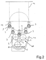
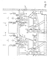
- the system shown in Figure 2 forms part of the workpiece processing device shown in Figure 3.
- the coating workpieces by an endless revolving shown only indicated here Link chain 12 transported.
- the transported through the link chain 12, on pivotally movable, in the transport direction deflectable transport tabs 13 held Workpieces are in a first coating station A with a first Application medium coated and then arrive after running one Drying oven (not shown) in a second coating station B, which in its Structure essentially that described above in connection with Fig.2 Device corresponds.
- the first coating station A and the second coating station B are each with a positioning device for setting a basic position of the respective Coater.
- the positioning device assigned to the first coating station here comprises two operable by hand crank devices 15 and 16 Spindle elements.
- the first coating station A is therefore both horizontal Direction as well as in the vertical direction of the respective workpiece dimensions can be positioned accordingly.
- the second coating station is also manual actuable hand crank devices 17 and 18 can be pre-positioned.
- the so prepositioned coating stations A and B are by separate drive units 19, 20 can be brought into a processing position in cycles, in particular can be raised, in which an application medium on the correspondingly fed workpiece 3 can be applied and the workpiece is possibly lifted off the holding mandrel.
- the drive units are used for the further transport of the coated workpieces 3 controlled such that at least the coating rollers 1, 2 or the whole Coating unit including housing can be lowered briefly so that the coated workpiece is removed and a new workpiece is fed can, without this resulting in uncontrollable contact of the workpieces and the coating roller comes.
- the structure of the coating stations A and B corresponds to that in FIG Connection with Fig. 2 described coating device. If necessary, you can of course i. V. m. a coating station A or B also coating stations can be used with a different structure.
- one or more of the coating rollers 1,2 also a contoured peripheral surface (here with two coating sections 1 a, 1b) have, in the event that only a portion 3a, 3b of the workpiece 3 to be coated while the rest of the workpiece is being coated (also from subsequent treatment, e.g. on an adhesive coating) remains free.
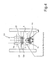
- FIG. 4 is one for carrying out a workpiece inner and / or outer coating provided embodiment of a device according to the invention shown.
- one is along its inner and / or outer peripheral surface rotationally symmetrical workpiece 3 to be coated onto a Bracket, e.g. a pair of support rollers 11 placed.
- This pair of support rollers 11 forms here the pair of support rollers supporting the workpiece at two support areas WP.
- the pair of support rollers at the same time form coating rollers for an outer coating of the workpiece 3 and can also be coupled to drive means for a rotary connection.
- the workpiece 3 to be coated can be rotated by the pair of support rollers 11 stored.
- a coating roller 1 provided with a coating medium into the workpiece 3 retracted.
- the coating roller 1 is connected to a rotary drive device.
- the workpiece 3 rests on the support rollers 11.
- the coating roller 1 and the workpiece supported on the support rollers 11 3 forms a uniform layer on the inner peripheral surface of the workpiece 3 from the application medium fed through the coating roller 1.
- a particularly uniform supply of the coating roller 1 with the coating medium can by means of feed channels formed in the coating roller 1 can be achieved.
- the pure rotary drive of the workpiece 3 can (Internal) coating roller 1 when the workpiece is rotatably supported by the support roller pair be enough.
- the coating roller 1 is preferably on a vertically movable here Carriage S mounted so that the workpiece 3 through the coating roller upwards moved to the frictional contact and rotary drive by the two drive rollers 28, 29 can be.
- the workpiece is driven in rotation via a workpiece drive motor 25, a here designed as an angular gear mechanism 26 and a coupled thereto Output gear 27.
- the output gear 27 is with the two drive rollers 28, 29th drive-connected.
- the workpiece 3 is lifted over the coating roller 1 and pressed against the drive rollers 12, 29. This becomes a forced drive of the workpiece 3 is reached and a uniform, high-quality coating is ensured.
- the lifting of the workpiece for the coating process has the Another advantage that the pair of support rollers 11 (without expensive ball bearings) can simply be carried out in the form of fixed support spikes. Besides, that will lower platen pair 11 then not in contact with coating material brought.
- the upper, raised drive rollers 28, 29 can also be used as Outside coating rollers can be formed.
- the coating roller 1 is, based on the workpiece 3, possibly in the radial direction movable.
- the coating roller 1 can as soon as the desired coating of the Inner surface of the workpiece 3 is reached, gradually from the inner peripheral surface of the Workpiece 3 are lifted off.
- the coating roller is preferred 1 continues to drive, causing the formation of any streaks on the inner peripheral surface of the workpiece 3 is avoided.
- the from the inner peripheral surface of the The workpiece 3 lifted coating roller 1 can now in the axial direction of the workpiece 3 are pulled out of the inner region of the workpiece 3.
- the workpiece can continue, in particular also inside a drying oven be rotated.
- Such an inner coating of the workpiece can be but also with the rotary table previously described in connection with Fig.1 carry out.
- the corresponding ones to be coated on the inside and / or outside Workpieces to those identified by the reference number 11 in FIG Support rollers (possibly also coating rollers) placed on and similar to the previous one described by means of a rotary drive inserted into the workpieces 3 Coating roller 1 coated.
- Drive rollers also force the respective workpiece to rotate movable.
- the workpiece also by lifting in drive connection with upper rotating drive rollers to be brought.
- the inner coating roller 1 by means of a vertically movable mandrel for guiding the workpiece into a drive and Coating layer replaceable (for external coating).
- Figure 5 shows a coating device again in a schematic representation a coating roller 1. If necessary, this can also be provided twice and the workpiece 3 through the coating rollers 1, 2 in a similar manner as in Fig. 1 be supported, the coating roller arrangement here being profiled Coating surface with coating sections 1a, 1b, in the event that only a cylinder section (two cylinder sections in the present example) of the workpiece 1 to be coated with edge scraper coating edge, while the other areas of the workpiece remain free of a coating.
- the device according to the invention is particularly suitable for coating ring or tubular components. With the device according to the invention also comparatively viscous fluids reliably on the corresponding Apply workpieces. This will result in a significantly reduced solvent consumption reached.
- the drying time of the coating medium is also determined by shortens the device according to the invention. Through reliable synchronization the rotational movement of the workpiece to be coated and the associated one Coating roller achieves a high surface quality. By the clock Moving or lowering or lifting the coating rollers is a collision-free Workpiece transport guaranteed.
- Vibration damper sleeves are on radially from one Round table 10 projecting holding mandrels attached by means of a handling system.
- a correspondingly arranged on a holding mandrel 9 vibration damper sleeve 3 is lowered by rotating the rotary table 10 over an initially Coating device positioned.
- the coating device in the vertical direction raised until the vibration damper sleeve with its outer peripheral area sits on the first coating roller 1 and the second coating roller 2.
- the constantly rotating two application rollers 1 and 2 also displace them their own weight in the gap formed between the two application rollers 1 and 2 penetrating vibration damper sleeve in rotation and together support that Workpiece in the radial direction.
- the corrosion protection paint collecting in the bottom area of the tub 4 becomes continuous dispensed on the two coating rollers 1 and 2 and arrives thereby on the outer peripheral surface of the vibration damper sleeve.
- the Vibration damper sleeve 3 sufficiently in the area of its outer peripheral surface the corrosion protection paint is coated, the coating device is again lowered in the vertical direction and another, initially still uncoated Workpiece positioned over the coating device.
- Vibration damper sleeve is simultaneously moved further and gets into one Drip-off position into which, if necessary, drip-off corrosion protection paint into the tub 4 and thus can get back into the application medium sump 5.
- the coating device is raised again towards the workpiece 3.
- the invention is not restricted to the exemplary embodiment described above.
- the workpiece it is also possible to use the workpiece to be coated without the aid a rotary table or a transport chain, for example by means of a transfer device in the nip area formed between the two coating rollers 1 and 2 appeal.
- a transfer device in the nip area formed between the two coating rollers 1 and 2 appeal.
- Both when using the rotary table and when using the transport chain it is advantageously possible to use the coating device to move along a certain distance in the workpiece transport direction. This makes it possible to keep the rotary table or the transport chain constant To operate transport speed.
- these coating stations on different pitch circles preferably (seen in the radial direction) be arranged "on gap", so that the clock variability of the overall device (also in connection with a dryer and / or cycle-coordinated application of loading and unloading stations) and e.g. an odd number of Workpiece holding stations, arranged on a pitch circle, in connection with a even number of workpiece receiving stations, arranged on one further e.g. Pitch circle further outward can be provided.
- FIG. 6a Such a rotary table device is shown in FIG. 6a, in which a series of the first Workpiece receptacles 30 arranged on a radially outer first pitch circle 31 are. Within this first pitch circle there is a second pitch circle 32, on which a series of second workpiece holders 33 is arranged.
- the first are Workpiece receptacles 30, based on the second workpiece receptacles 33 for a gap arranged. Both the first workpiece fixtures and the second workpiece fixtures are provided in an odd number.
- the first and second workpiece holders 30, 33 are not about the axis of rotation Z of the rotary table device movable, but stationary with the rotary table device coupled. However, it is also possible to use the two pitch circle arrangements to be relatively movable to each other.
- the first and second workpiece holders 30, 33 formed such that the workpieces moved along the first pitch circle 31 towards the workpieces moving along the second pitch circle 32 are at a different axial height level.
- the radially inner second workpiece receptacles 33 Workpieces, seen in the vertical direction, higher than those lying further out first workpiece receptacles 30. This makes access to reached the workpieces held radially on the inside.
- Both the first workpiece holders 30 and the second workpiece holders 33 are provided with a drive device through which the in the workpiece holders each workpiece held rotatable about a vertical axis are.
- those in the first workpiece holders 30 held workpieces rotated at the same speed as that by the second workpiece holders 33 held workpieces.
- the workpiece turning organs of the first and second workpiece holders 30, 33 can, for example by means of a toothed belt.
- An external one is preferred first workpiece holder 30 with an adjacent inner second Workpiece holder 33 coupled.
- the rotary drive of the workpiece holding elements then takes place in the respective processing or treatment station by coupling a stationary drive device to the workpiece holders 30, 33.
- the switching of the rotary table device according to a predetermined Switching pattern is carried out by means of a rotary table drive device 34, which is in the present In the case of one controlled by a control device (not shown) Electric motor 35 which, via a gear 36 with a coaxial on the Rotary table transport device 10 attached drive gear 37 with the rotary table device 10 is coupled.
- the rotary table device 10 is rotatably supported in the exemplary embodiment shown through a roller bearing 38 that rotates a stationary base frame 39 couples with the rotary table device 10.
- a roller bearing 38 that rotates a stationary base frame 39 couples with the rotary table device 10.
- the height at which they are arranged along the inner second pitch circle 32 Workpieces held opposite the top of the rotary table device 10 are, preferably corresponds approximately to the radius of the inner, second partial circle 32.
- Workpieces held opposite the top of the rotary table device 10 are, preferably corresponds approximately to the radius of the inner, second partial circle 32.
- For coupling the workpieces to the workpiece holders 30, 33 can preferably rod-like, preferably arranged coaxially to the workpiece axis of rotation Holding members 42 are used. This advantageously makes it possible an undesirable precipitation of the application medium on the first and second To avoid workpiece holders 30, 33.
- the present invention enables a permissible number of workpiece pickups on a rotating transport device, preferably a rotary table, in Depends on the number of treatments required / possible per workpiece (Drying) and / or processing (coatings) determined by the permissible Number of workpiece holders from a common multiple of the number possible treatments and / or treatments determined and then provided is that from this and the number of planned / possible edits certain quotient is an integer.
Abstract
Description
Die Erfindung betrifft ein Verfahren und eine Vorrichtung zur Bearbeitung, insbesondere Beschichtung, von Werkstücken.The invention relates to a method and a device for processing, in particular Coating of workpieces.
Die Beschichtung rotationssymmetrischer und insbesondere hohlzylindrischer Werkstücke, z.B. zur Vorbereitung der Oberflächen konzentrisch angeordneter, miteinander durch ein schwingungsdämpfendes Material zu verbindender Zylinder, wie sie z.B. als Motoraufhängungen oder Stoßdämpfer im Fahrzeugbau benötigt werden, erfolgt in herkömmlicher Weise, indem die Werkstücke beispielsweise mittels einer Förderkette in eine Beschichtungsvorrichtung eingebracht werden, in welcher ein entsprechendes Beschichtungsmedium auf die Werkstücke aufgesprüht oder gegen die Werkstücke gewirbelt wird. Die Dicke einer sich hierbei auf dem jeweiligen Werkstück niederschlagenden Schicht kann beispielsweise über die Verweildauer des Werkstückes in der Beschichtungsvorrichtung gesteuert werden. Der Innenbereich einer derartigen Beschichtungsvorrichtung muß von Zeit zu Zeit gereinigt werden, da das aufgewirbelte oder versprühte, nicht von dem Werkstück aufgenommene Beschichtungsmedium sich teilweise im Innenbereich der Beschichtungsvorrichtung festsetzt. Die Produktivität derartiger Vorrichtungen wird in hohem Maße von der Trocknungsdauer des Beschichtungsmediums bestimmt und ist bei langsam trocknenden bzw. aushärtenden Beschichtungsmedien vergleichsweise gering.The coating of rotationally symmetrical and in particular hollow cylindrical workpieces, e.g. to prepare the surfaces concentrically arranged, with each other cylinder to be connected by a vibration-damping material, such as e.g. as Engine suspensions or shock absorbers are required in vehicle construction conventionally, for example, by means of a conveyor chain be introduced into a coating device in which a corresponding Coating medium sprayed onto the workpieces or against the workpieces is whirled. The thickness of one that is deposited on the respective workpiece Layer can, for example, in the dwell time of the workpiece the coating device can be controlled. The interior of such Coating device must be cleaned from time to time, as the whirled up or sprayed coating medium not absorbed by the workpiece partially stuck in the interior of the coating device. The productivity such devices is largely dependent on the drying time of the Coating medium is determined and is slow drying or curing Coating media comparatively low.
Alternativ zu derartigen Sprüh- oder Wirbelbeschichtungsvorrichtungen ist es möglich, das Beschichtungsmedium durch Beschichtungswalzen auf die Werkstücke aufzubringen. Die Oberflächenqualität der derart erzeugten Beschichtungen wird hierbei jedoch von der Größe der Werkstücke und der Drehzahl der Beschichtungswalze beeinflußt. Die Abstimmung entsprechender Systeme erfordert besondere Sorgfalt.As an alternative to such spray or fluid coating devices, it is possible to apply the coating medium to the workpieces by coating rollers. However, the surface quality of the coatings produced in this way will on the size of the workpieces and the speed of the coating roller affected. The coordination of appropriate systems requires special care.
Der Erfindung liegt die Aufgabe zugrunde, ein Verfahren und eine Vorrichtung zur Bearbeitung, insbesondere Beschichtung von insbesondere zylinderförmigen Werkstücken zu schaffen, durch welche auch im Rahmen eines weitgehend automatisierten Bearbeitungs-, insbesondere Beschichtungsvorganges bei hoher Produktivität qualitativ hochwertige Beschichtungen der jeweiligen Werkstücke erreichbar sind. The invention has for its object a method and a device for processing, in particular coating of in particular cylindrical workpieces to create through which also within the framework of a largely automated Machining, especially coating process with high productivity qualitatively high-quality coatings of the respective workpieces can be achieved.
Diese Aufgabe wird erfindungsgemäß durch ein Verfahren mit den in Anspruch 1 angegebenen
Merkmalen gelöst sowie durch eine Vorrichtung mit den Merkmalen des
Anspruches 8. Auf diese Weise ist es sehr vorteilhaft möglich, die Anzahl der Werkstückaufnahmen
in Abhängigkeit von der Anzahl der Bearbeitungs-, insbesondere Beschichtungsschritte
unter Berücksichtigung eines zwischen zwei Beschichtungsvorgängen
erfolgenden Trockenvorganges (Behandlungsstation) exakt zu bestimmen.This object is achieved according to the invention by a method with the specified in
In vorteilhafter Weise wird es möglich, das jeweils zu beschichtende Werkstück während der Beschichtung mit dem Beschichtungsmedium stabil und schwingungsarm zu lagern und die Beschichtungswalze definiert mit der Werkstückoberfläche in innigen Kontakt zu bringen. Ein Taumeln des Werkstücks wird hierbei auf zuverlässige Weise verhindert. Auch große und vergleichsweise schwere Werkstücke können unter vergleichsweise hoher Drehzahl gedreht und zuverlässig beschichtet werden.In an advantageous manner, it becomes possible for the workpiece to be coated during the coating with the coating medium is stable and low-vibration store and the coating roller defined with the workpiece surface inside To get in touch. The workpiece wobbles in a reliable manner prevented. Even large and comparatively heavy workpieces can be compared rotated at high speed and coated reliably.
Zur Durchführung einer Werkstück-Außenbeschichtung enthält die Abstützwalzenpaaranordnung für das zum Beispiel auf einem Dorn gehaltene Werkstück gemäß einer bevorzugten Ausführungsform der Erfindung zugleich eine zur Beschichtung mit dem Beschichtungsmedium vorgesehene Beschichtungswalze. Vorzugsweise bilden beide Walzen der Abstützwalzenpaaranordnung Beschichtungswalzen. Die beiden Walzen der Abstützwalzenpaaranordnung drehen sich vorzugsweise mit gleicher Umfangsgeschwindigkeit. Die Produktzufuhr des Beschichtungsmaterials zu den beiden Beschichtungswalzen des Beschichtungswalzenpaares kann jedoch z.B. durch eine Übertragerwalze unabhängig und für jede Walze individuell gesteuert werden.The support roller pair arrangement contains for carrying out a workpiece outer coating for the workpiece held on a mandrel, for example, according to a preferred embodiment of the invention at the same time a for coating coating roller provided for the coating medium. Form preferably both rollers of the support roller pair arrangement of coating rollers. The two Rollers of the support roller pair arrangement preferably rotate with the same Circumferential speed. The product supply of the coating material to the two Coating rollers of the pair of coating rollers can, e.g. by a transfer roller can be controlled independently and individually for each roller.
Zur Durchführung einer Werkstück-Innenbeschichtung ist zusätzlich zur Abstützwalzenpaaranordnung eine hiervon separate und in das Werkstück einfahrbare, z.B. auch selbständig rotierend antreibbare Beschichtungswalze vorgesehen.To carry out a workpiece inner coating is in addition to the support roller arrangement a separate one and retractable into the workpiece, e.g. also provided independently rotating drivable coating roller.
Das zu beschichtende Werkstück wird während des Beschichtungsvorganges gedreht, entweder durch reibschlüssige Mitnahme auf der Abstütz- und/oder Beschichtungswalzenpaaranordnung oder zwangsweise durch eine entweder mit der Abstützund/oder Beschichtungswalzenpaaranordnung gekoppelte oder separate Antriebseinrichtung für die Beschichtungswalze. Das Antriebsdrehmoment wird vorzugsweise reibschlüssig über eine an dem Werkstück angreifende Koppelungseinrichtung übertragen. Eine derartige Koppelungseinrichtung besteht vorzugsweise aus einem an dem Werkstück umfangsseitig angreifenden Rollenpaar oder eine innen- oder stirnseitig an dem Werkstück angreifenden Spindeleinrichtung. Ein entsprechendes Rollenpaar kann durch die Abstützrollenpaaranordnung selbst oder separat hiervon ausgebildet sein. Eine entsprechende Spindeleinrichtung ist vorzugsweise auch als Werkstückstückhalteeinrichtung (Dorn) wirksam.The workpiece to be coated is rotated during the coating process, either by frictional entrainment on the support and / or coating roller pair arrangement or forcibly by either with the support and / or Coating roller pair arrangement coupled or separate drive device for the coating roller. The drive torque is preferred frictionally transmitted via a coupling device acting on the workpiece. Such a coupling device preferably consists of one the workpiece on the circumferentially engaging pair of rollers or an inside or front on the workpiece engaging spindle device. A corresponding pair of roles can be formed by the support roller pair arrangement itself or separately therefrom his. A corresponding spindle device is preferably also as Workpiece holding device (mandrel) effective.
Gemäß einer bevorzugten Ausführungsform der Erfindung weist die Beschichtungsmedium-Zufuhreinrichtung ein Walzenelement auf, dessen Längsachse im wesentlichen parallel zu einer Längsachse der Beschichtungswalze verläuft, wobei das Walzenelement eine Umfangsfläche aufweist, die mit der Beschichtungswalze in Berührungskontakt bringbar ist. Dadurch wird es auf vorteilhafte Weise möglich, das zur Werkstückbeschichtung vorgesehene Beschichtungsmedium gleichmäßig verteilt an die Beschichtungswalze abzugeben. Dieses Walzenelement weist vorzugsweise eine elastisch nachgiebige, ggf. stark saugfähige Außenbeschichtung auf.According to a preferred embodiment of the invention, the coating medium supply device has a roller element, the longitudinal axis of which is essentially runs parallel to a longitudinal axis of the coating roller, the roller element has a peripheral surface in contact with the coating roller is feasible. This makes it possible in an advantageous manner The coating medium provided for the workpiece coating is evenly distributed deliver the coating roller. This roller element preferably has one elastic, possibly highly absorbent outer coating.
Eine im Hinblick auf eine besonders gleichmäßige Beschichtung der Werkstücke vorteilhafte Ausführungsform der Erfindung ist dadurch gegeben, daß eine zweite Beschichtungswalze vorgesehen ist, die von der ersten Beschichtungswalze beabstandet vorzugsweise achsparallel angeordnet ist und die eine zweite Beschichtungsfläche bildet, die mit dem Werkstück in Berührungskontakt bringbar ist. Die beiden Beschichtungswalzen sind hierbei vorzugsweise derart angeordnet, daß das Werkstück in dem zwischen den beiden Beschichtungswalzen gebildeten Zwickel auf den beiden Walzen aufliegt und sich dabei selbsttätig zentriert. Eine besonders zuverlässige selbsttätige Zentrierung des Werkstückes wird dadurch erreicht, daß der Abstand zwischen den Beschichtungsflächen der beiden Beschichtungswalzen ca. 10 bis 30 % kleiner ist als der Durchmesser des Werkstückes. Vorzugsweise ist das walzenförmige Beschichtungselement zur gleichzeitigen Übertragung des Beschichtungsmediums symmetrisch dem Abstütz- und Beschichtungswalzenpaar unterhalb desselben angeordnet.An advantageous one with regard to a particularly uniform coating of the workpieces Embodiment of the invention is given in that a second coating roller is provided, which is spaced from the first coating roller is preferably arranged axially parallel and the one second coating surface forms, which can be brought into contact with the workpiece. The two coating rollers are preferably arranged such that the workpiece in the gusset formed between the two coating rollers on the two Rolls rests and is centered automatically. A particularly reliable one automatic centering of the workpiece is achieved in that the distance between the coating areas of the two coating rollers approx. 10 to 30% is smaller than the diameter of the workpiece. This is preferably roller-shaped Coating element for the simultaneous transfer of the coating medium arranged symmetrically below the pair of support and coating rollers.
Die erste und die zweite Beschichtungswalze sind in vorteilhafter Weise mittels einer Antriebseinrichtung gleichsinnig drehangetrieben. Dadurch wird auf vorteilhafte Weise das zu beschichtende Werkstück durch die beiden Beschichtungswalzen in Drehung versetzt. Dadurch wird ein besonders gleichmäßiger Auftrag des Beschichtungsmediums auf die entsprechend auf den Beschichtungswalzen aufliegende Werkstückfläche gewährleistet. Gemäß einer bevorzugten Ausführungsform der Erfindung werden die beiden Beschichtungswalzen derart angetrieben, daß sich, bezogen auf diese Beschichtungsflächen, gleiche Umfangsgeschwindigkeiten ergeben. Alternativ dazu ist es jedoch auch möglich, durch entsprechende Abstimmung der Drehzahlen der Beschichtungswalzen oder auch durch entsprechende Bemessung des Durchmessers der jeweiligen Beschichtungswalze geringfügig unterschiedliche Umfangsgeschwindigkeiten zu realisieren, wodurch ein gewisser Umfangsschlupf zwischen dem Werkstück und den Beschichtungsflächen der jeweiligen Beschichtungswalze erreicht wird. Dadurch kann die Haftung des Beschichtungsmediums noch weiter verbessert werden.The first and the second coating roller are advantageously by means of a Drive device driven in the same direction. This will be advantageous the workpiece to be coated is rotated by the two coating rollers added. This ensures a particularly even application of the coating medium on the workpiece surface corresponding to the coating rollers guaranteed. According to a preferred embodiment of the invention, the driven both coating rollers in such a way that, based on these coating surfaces, result in the same peripheral speeds. Alternatively, it is however, it is also possible to adjust the speeds of the coating rollers accordingly or also by appropriate dimensioning of the diameter the respective coating roller slightly different peripheral speeds to realize, causing a certain amount of circumferential slip between the workpiece and the coating areas of the respective coating roller is reached. This can further improve the adhesion of the coating medium.
Die Auflage des Werkstückes auf der Abstützwalzenpaaranordnung, die vorzugsweise zugleich ein Paar Beschichtungswalzen für die Außenbeschichtung eines zylindrischen Werkstückes bildet, ermöglicht eine lagestabilisierte Beschichtung und zuverlässige Fixierung des rotierenden, eine zylindrische Konfigurationen aufweisenden Werkstückes. Hierdurch kann auch ein doppelter Auftrag auf das Werkstück, d.h. verdoppelte Schichtdicken (z.B. eines hochbelastbaren Haftgrundes) auf dem Werkstück erreicht werden.The support of the workpiece on the support roller pair arrangement, which is preferred at the same time a pair of coating rollers for the external coating of a cylindrical one Forms workpiece, enables a position-stabilized coating and reliable Fixation of the rotating, cylindrical configurations Workpiece. As a result, a double job on the workpiece, i.e. doubled Layer thicknesses (e.g. a heavy-duty primer) on the workpiece can be achieved.
Nach einer ebenfalls bevorzugten Ausführungsform kann die zumindest eine Beschichtungswalze (oder auch das Beschichtungswalzenpaar) eine profilierte Oberfläche und damit auch eine profilierte Beschichtungsgeometrie aufweisen, wobei es ohne produktionstechnisch lästige Abdeckungen oder dergleichen möglich ist, nur einen bestimmten Umfangsabschnitt (bzw. Teilzylinderfläche) der gesamten Mantelfläche des Werkstücks mit sehr exakter Begrenzung zu beschichten. Dies ist insbesondere für die Fälle wichtig, bei denen später nur eine weitere Teilbeschichtung des Werkstücks erfolgt, ein anderer Bereich des Werkstücks aber von Beschichtungen oder Verbindungsmitteln - z.B. für das Aufvulkanisieren von Gummisperren für Stoßdämpfer - frei bleiben soll.According to a likewise preferred embodiment, the at least one coating roller (or the pair of coating rollers) a profiled surface and thus also have a profiled coating geometry, it being without production-related annoying covers or the like is possible, only one certain circumferential section (or partial cylinder surface) of the entire lateral surface to coat the workpiece with very precise limitation. This is particularly so important for cases in which only a further partial coating of the workpiece later another area of the workpiece but of coatings or Lanyards - e.g. for vulcanizing rubber locks for shock absorbers - should remain free.
Gemäß einer bevorzugten Ausführungsform der Erfindung ist eine Beschichtungsmedium-Zufuhreinrichtung vorgesehen zur Zufuhr eines Beschichtungsmediums auch zu der zweiten Beschichtungswalze. Der der jeweiligen Beschichtungswalze zugeführte Mengenstrom an Beschichtungsmedium ist in vorteilhafter Weise jeweils separat einstellbar. Dadurch kann auf besonders feinfühlige Weise Einfluß auf den Aufbau der auf dem Werkstück gebildeten Beschichtung genommen werden. Da üblicherweise sowohl über die erste Beschichtungswalze als auch über die zweite Beschichtungswalze jeweils das gleiche Beschichtungsmedium auf das Werkstück aufgebracht werden soll, ist es möglich, die Zufuhreinrichtung zur Zufuhr des Beschichtungsmediums für beide Beschichtungswalzen zu verwenden.According to a preferred embodiment of the invention is a coating medium supply device also intended to supply a coating medium the second coating roller. The one fed to the respective coating roller The quantity flow of coating medium can advantageously be set separately in each case. This can influence the structure of the in a particularly sensitive way be taken on the coating formed on the workpiece. Because usually both over the first coating roller and over the second coating roller the same coating medium is applied to the workpiece , it is possible to use the feed device for feeding the coating medium to be used for both coating rollers.
Die Zufuhreinrichtung weist gemäß einer bevorzugten Ausführungsform der Erfindung eine Transferwalze auf, die mit wenigstens einer der Beschichtungswalzen in Berührungskontakt bringbar ist. Der Durchmesser dieser Transferwalze ist gemäß einer bevorzugten Ausführungsform kleiner als der Durchmesser der zugeordneten Beschichtungswalze. Die Transferwalze dreht sich dabei mit einer höheren Drehzahl als die Beschichtungswalze, wodurch ein besonders gleichmäßiger Übergang des Beschichtungsmediums auf die Beschichtungswalze erreicht wird.According to a preferred embodiment of the invention, the feed device points a transfer roller in contact with at least one of the coating rollers is feasible. The diameter of this transfer roller is according to a preferred one Embodiment smaller than the diameter of the assigned coating roller. The transfer roller rotates at a higher speed than the coating roller, which ensures a particularly smooth transition of the coating medium is reached on the coating roller.
Die Zufuhreinrichtung für das Beschichtungsmedium ist gemäß einer bevorzugten Ausführungsform der Erfindung mit einem Medium-Aufnahmebereich versehen, in welchem das Beschichtungs-Medium bevorratet ist. Dieser Aufnahmebereich bildet bei einer bevorzugten Ausführungsform der Erfindung einen Sumpf für die Beschichtungsflüssigkeit (insbesondere Haftmittel bzw. Haftgrund für spätere Elastomerbeschichtungen), in welchen eine mit der Transferwalze zusammenwirkende Transfereinrichtung eintaucht. Diese Transfereinrichtung besteht beispielsweise aus einer Drehwalze, die mit der Transferwalze in Kontakt bringbar ist zum Übertragen des Beschichtungsmediums aus dem Sumpf auf die Transferwalze. Alternativ dazu kann die Transfereinrichtung auch beispielsweise durch ein elastisches Band gebildet sein, das auf ein entsprechendes Walzenpaar aufgespannt ist.The supply device for the coating medium is according to a preferred one Embodiment of the invention provided with a medium receiving area, in which the coating medium is stocked with. This recording area forms in a preferred embodiment of the invention, a sump for the coating liquid (especially adhesive or primer for later elastomer coatings), in which a transfer device cooperating with the transfer roller dips. This transfer device consists of, for example Rotating roller that can be brought into contact with the transfer roller for transferring the coating medium from the swamp to the transfer roller. Alternatively, the Transfer device can also be formed, for example, by an elastic band is clamped onto a corresponding pair of rollers.
Eine insbesondere im Hinblick auf eine besonders günstige Reinigung bzw. Wartung der erfindungsgemäßen Vorrichtung vorteilhafte Ausführungsform ist dadurch gegeben, daß die Zufuhreinrichtung für das Beschichtungsfluid in einer Gehäusewanne aufgenommen ist und der Sumpf im unteren Bereich der Gehäusewanne gebildet ist. A particularly in view of a particularly cheap cleaning or maintenance The advantageous embodiment of the device according to the invention is given by that the supply device for the coating fluid in a housing trough is recorded and the sump is formed in the lower region of the housing trough.
Dadurch wird es auf vorteilhafte Weise möglich, die Zufuhreinrichtung auf einfache Weise auszuwechseln.This advantageously makes it possible for the feed device to be simple Way to change.
Gemäß einer besonders bevorzugten Ausführungsform der Erfindung ist wenigstens eine der Beschichtungswalzen bzw. die Walzen der Abstützwalzenpaaranordnung in im wesentlichen vertikaler Richtung, insbesondere taktweise, anhebbar bzw. absenkbar. Dadurch wird es möglich, die Beschichtungsvorrichtung unterhalb eines Transportpfades, entlang welchem die zu beschichtenden Werkstücke transportiert werden, abzusenken und die Beschichtungswalzen nur unmittelbar zur Beschichtung des Werkstücks an das Werkstück heranzufahren, sobald sich das entsprechende Werkstück in einer Bearbeitungsposition befindet. Die seitens der Beschichtungswalze in vertikaler Richtung zurückgelegte Wegstrecke ist dabei derart bemessen, daß die Beschichtungswalze in abgesenkter Position eine anschließende Transportbewegung der Werkstücke nicht behindert. Die Bildung etwaiger Schlieren auf der Werkstückoberfläche durch ein unkontrolliertes Inkontakttreten der Werkstücke mit den Beschichtungswalzen beim Weiterschalten wird dabei vermieden.According to a particularly preferred embodiment of the invention, at least one of the coating rollers or the rollers of the support roller pair arrangement in essentially vertical direction, in particular in cycles, can be raised or lowered. This makes it possible to place the coating device below a transport path, along which the workpieces to be coated are transported, lower and the coating rollers only directly for coating the Approach the workpiece as soon as the corresponding workpiece is in a processing position. On the part of the coating roller in The distance covered in the vertical direction is dimensioned such that the coating roller a subsequent transport movement in the lowered position the workpieces are not hindered. The formation of any streaks on the workpiece surface through an uncontrolled contact of the workpieces with the coating rollers when switching on is avoided.
Selbstverständlich kann auch die gesamte Beschichtungseinheit, bestehend aus einer unteren Material-Aufnahmewalze, der Transferwalze und dem Beschichtungs- bzw. Abstützwalzenpaar - auch in Verbindung mit dem umgebenden Gehäuse - vertikal beweglich angeordnet sein.Of course, the entire coating unit, consisting of one lower material pick-up roller, the transfer roller and the coating or Support roller pair - also in connection with the surrounding housing - vertically be arranged movably.
Dadurch wird es möglich, die Beschichtungswalzen ständig mit der ihr zugeordneten Transferwalze in Berührungskontakt zu halten. Die Transferwalze kann dabei sowohl während des Werkstückbeschichtungsvorganges, d.h. während die Beschichtungswalze mit dem zu beschichtenden Werkstück in Kontakt steht, als auch in abgesenkter Position der Beschichtungswalze Beschichtungsmedium zuführen.This makes it possible to constantly coat the coating rollers with the one assigned to them Keep the transfer roller in contact. The transfer roller can both during the workpiece coating process, i.e. while the coating roller is in contact with the workpiece to be coated, as well as in lowered Position the coating roller.
Bei einer anderen Ausführungsform der Vorrichtung mit wenigstens zwei zur Beschichtung eines Werkstücks vorgesehenen Beschichtungswalzen sind diese beiden Beschichtungswalzen auf geringfügig unterschiedlichem Höhenniveau angeordnet. Dadurch wird eine besonders stabile Führung des zu beschichtenden Werkstücks zwischen den beiden Beschichtungswalzen erreicht. Die beiden Beschichtungswalzen sind vorzugsweise derart angeordnet, daß der Berührungskontaktabschnitt zwischen Beschichtungswalze und Werkstück relativ zur Rotationsachse der Beschichtungswalze bzw. Abstützwalze derart angeordnet ist, daß eine Verbindungslinie durch den Berührungskontaktabschnitt und die Rotationsachse gegenüber der Horizontalen einen Winkel im Bereich von 30 bis 60° einschließt. Winkel im Bereich zwischen 30 und 45° erweisen sich insbesondere bei vergleichsweise leichten Werkstücken als vorteilhaft. Winkel im Bereich zwischen 45 bis 60° erweisen sich bei größeren bzw. schwereren Werkstücken als vorteilhaft.In another embodiment of the device with at least two for coating Coating rollers provided on a workpiece are these two Coating rollers arranged at slightly different height levels. This ensures particularly stable guidance of the workpiece to be coated reached between the two coating rollers. The two coating rollers are preferably arranged such that the touch contact portion between Coating roller and workpiece relative to the axis of rotation of the coating roller or support roller is arranged such that a connecting line through the Touch contact section and the axis of rotation relative to the horizontal one Includes angles in the range of 30 to 60 °. Angles in the range between 30 and 45 ° have proven to be particularly advantageous for comparatively light workpieces. Angles in the range between 45 to 60 ° prove to be larger or heavier Workpieces as advantageous.
Die Beschichtungsfläche der Beschichtungswalze ist in vorteilhafter Weise aus einem Weichstoff-Material, insbesondere einem geschäumten Gummimaterial gebildet. Es ist auch möglich, die Beschichtungswalze mit einem Überzug aus einem saugfähigen Textil-Material zu versehen, zur bevorratenden Aufnahme der Beschichtungsflüssigkeit.The coating surface of the coating roller is advantageously made of one Soft material, in particular a foamed rubber material. It it is also possible to coat the coating roller with an absorbent coating To provide textile material for the storage of the coating liquid.
Eine zur Ausbildung einer Innenbeschichtung eines im wesentlichen hohlzylinderförmigen Werkstückes vorteilhafte Ausführungsform der Vorrichtung ist dadurch gegeben, daß die Beschichtungswalze durch eine Walze gebildet ist, deren Außendurchmesser kleiner ist als der Innendurchmesser des zu beschichtenden Innenbereichs des Werkstücks. Die Beschichtungswalze ist hierzu derart ausgestaltet, daß diese in den Innenbereich des Werkstücks einführbar ist. Dadurch wird es auf vorteilhafte Weise möglich, die Innenfläche des Werkstückes gleichmäßig mit der Beschichtungsflüssigkeit zu beschichten. Auch hierbei ist selbstverständlich eine profilierte Geometrie (z.B. unterschiedliche Durchmesser und/oder in axialer Richtung) voneinander beabstandete Auftragsabschnitte (getrennt durch Ringnuten) der Innenbeschichtungswalze möglich, wenn nicht die gesamte von der Beschichtungswalze erfaßbare Innenoberfläche des Werkstücks beschichtet werden soll.One for forming an inner coating of a substantially hollow cylindrical Workpiece advantageous embodiment of the device is given by that the coating roller is formed by a roller whose outer diameter is smaller than the inside diameter of the interior area to be coated of the workpiece. For this purpose, the coating roller is designed such that it is in the inside of the workpiece can be inserted. This will make it beneficial Possible way, the inner surface of the workpiece evenly with the coating liquid to coat. Here too, of course, there is a profiled geometry (e.g. different diameters and / or in the axial direction) from each other spaced application sections (separated by ring grooves) of the inner coating roller possible if not all that can be covered by the coating roller Inner surface of the workpiece to be coated.
Das zu beschichtende Werkstück ist in vorteilhafter Weise drehbar gelagert. Hierzu ist gemäß einer bevorzugten Ausführungsform der Erfindung eine Halteeinrichtung vorgesehen, wobei die Halteeinrichtung einen Haltedorn aufweist, auf den das Werkstück aufsteckbar ist. Zum Auftrag einer Innenbeschichtung ist es auch möglich, zur drehbewegbaren Lagerung des Werkstückes ein Auflagerollenpaar vorzusehen, auf welches das jeweilige Werkstück aufgelegt ist. The workpiece to be coated is advantageously rotatably supported. This is According to a preferred embodiment of the invention, a holding device is provided, wherein the holding device has a holding mandrel on which the workpiece is attachable. To apply an inner coating, it is also possible to apply a rotating one Storage of the workpiece to provide a pair of support rollers on which the respective workpiece is placed.
Wird das hohlzylindrische Werkstück zur Außen- oder Innenbeschichtung vertikal zum Reibkontakt mit einer Antriebs- und/oder Außenbeschichtungswalzenpaar bewegt, ist es auch ausreichend, anstelle von Auftragsrollen einfach feste Abstützdome zur Werkstückauflage in der unteren Position vorzusehen.Is the hollow cylindrical workpiece for external or internal coating vertical to Frictional contact with a drive and / or outer coating roller pair is moved it is also sufficient to simply use fixed support domes instead of application rolls Provide workpiece support in the lower position.
Der vorangehend genannte Haltedom eignet sich insbesondere bei der Ausbildung einer Werkstück-Außenbeschichtung. Das Auflagerollenpaar ermöglicht eine zuverlässige Abstützung des Werkstücks im Rahmen für eine Innenflächen-Beschichtung. Der Haltedom bzw. das Auflagerollenpaar sind in vorteilhafter Weise mit einer Antriebseinrichtung gekoppelt, so daß das Werkstück zwangsweise mit einer vorbestimmten, insbesondere auf die Umfangsgeschwindigkeit der Beschichtungswalze bzw. Beschichtungswalzen abgestimmten Drehzahl gedreht wird und über die Halteeinrichtung in Drehung versetzt werden kann. Die Übertragung des AntriebsDrehmomentes auf das Werkstück kann beispielsweise reibschlüssig über die beiden Auflagerollen erfolgen. Insbesondere bei der Verwendung des Haltedornes als Halteeinrichtung ist es auch möglich, diesen mit einer Spanneinrichtung ggf. mit konischen Zentrierdornen zu versehen, durch welche die Beschichtungswalze auf dem Haltedorn fest spannbar ist.The aforementioned Haltedom is particularly suitable for training a workpiece outer coating. The pair of support rollers enables reliable Support of the workpiece in the frame for an inner surface coating. The Haltedom or the pair of support rollers are advantageously with a drive device coupled so that the workpiece is forcibly with a predetermined, especially the peripheral speed of the coating roller or coating rollers is rotated at a coordinated speed and via the holding device can be rotated. The transmission of the drive torque For example, the workpiece can be frictionally engaged over the two Support rollers take place. Especially when using the holding mandrel as a holding device it is also possible to use a conical clamping device Centering mandrels to be provided, through which the coating roller on the holding mandrel is firmly clamped.
Die Halteeinrichtung ist gemäß einer bevorzugten Ausführungsform der Erfindung in eine Transporteinrichtung integriert. Diese Transporteinrichtung ist in vorteilhafter Weise durch einen Rundtisch gebildet. An diesem Rundtisch sind eine Anzahl Haltedorne bzw. Auflagerollenpaare vorgesehen, die im wesentlichen radial zur Rotationsachse des Rundtisches ausgerichtet sind. Dadurch wird es auf vorteilhafte Weise möglich, die entlang des Umfangs des Rundtisches radial ausgerichtet angeordneten Werkstücke sukzessive in den Arbeitsbereich der vorzugsweise taktweise an die Werkstücke heranbewegten Beschichtungsvorrichtung einzubringen. Die in der Beschichtungsvorrichtung beschichteten Werkstücke können nachfolgend in einen Trocknungsofen und nach Verlassen des Trocknungsofens ggf. wiederum in die Beschichtungsvorrichtung eingebracht werden, bis die auf den Werkstücken ausgebildete Schichtdicke eine vorgegebene Stärke erreicht hat. Es ist auch möglich, die zu beschichtenden Werkstücke vor dem erstmaligen Eintritt in die Beschichtungsvorrichtung in dem Trocknungsofen vorzuwärmen, wodurch sich ein besonders gleichmäßiger Auftrag des Beschichtungsmedium in der Beschichtungsvorrichtung ergibt. According to a preferred embodiment of the invention, the holding device is in a transport device integrated. This transport device is advantageous Formed by a round table. There are a number of holding mandrels at this rotary table or support roller pairs are provided, which are substantially radial to the axis of rotation of the rotary table are aligned. This will make it beneficial possible, arranged radially aligned along the circumference of the rotary table Workpieces successively in the work area, preferably in cycles to the Introduce workpieces moving coating device. The one in the coater coated workpieces can subsequently in one Drying oven and after leaving the drying oven, if necessary, again in the coating device be introduced until the formed on the workpieces Layer thickness has reached a predetermined thickness. It is also possible to do that too coating workpieces before entering the coating device for the first time preheat in the drying oven, which makes a particularly uniform Application of the coating medium in the coating device results.
Alternativ zu dem vorangehend beschriebenen Rundtisch oder auch in Kombination damit ist es auch möglich, die Transporteinrichtung durch eine Transportkette zu bilden. Die zu beschichtenden Werkstücke sind an der Transportkette vorzugsweise derart ausgerichtet angebracht, daß die Längsachse der Werkstücke quer zur Transportrichtung der Transportkette verläuft. Die Transportkette ist durch eine Vielzahl gelenkig gekoppelter Kettenglieder gebildet. Die Transportkette wird durch eine vorzugsweise durch Umlenkrollen gebildete Führungseinrichtung geführt. Die an der Transportkette angebrachten Halteeinrichtungen sind vorzugsweise derart ausgebildet, daß die zu beschichtenden Werkstücke im Bereich der Umlenkrollen aus der eigentlichen Kettenbahn herausgeschwenkt werden können. Hierzu sind die Haltedorne über einen kurzen Gelenkhebel schwenkbar mit der Transportkette verbunden. Die Haltedorne werden dabei durch die kurzen Gelenkhebel derart ausgerichtet an der Transportkette gehalten, daß die Mittelachse der Haltedorne sich im wesentlichen parallel zu einer Umlenkachse der Transportkette erstreckt.As an alternative to the rotary table described above or in combination it is also possible to form the transport device by means of a transport chain. The workpieces to be coated are preferred on the transport chain so aligned that the longitudinal axis of the workpieces transversely to the direction of transport the transport chain runs. The transportation chain is through a multitude articulated chain links formed. The transport chain is preferred by one guided by guide rollers formed guide. The on the Holding devices attached to the transport chain are preferably designed such that the workpieces to be coated in the area of the deflection rollers from the actual Chain conveyor can be swung out. The mandrels are for this connected to the transport chain via a short articulated lever. The Holding pins are aligned in such a way by the short articulated lever on the Transport chain held that the central axis of the holding mandrels are essentially parallel extends to a deflection axis of the transport chain.
Nach noch einer weiteren bevorzugten Ausführungsform der Erfindung können die Werkstückträger in dem Rundtisch (z.B. bei Aufnahme der Werkstücke im wesentlichen achsparallel zur Drehachse des Rundtisches zur Werkstückbehandlung in Sprühbeschichtungsstationen) auch entlang mehrerer Teilkreise (vorzugsweise "auf Lücke") angeordnet sein, so daß sowohl eine gerade als auch eine ungeradzahlige Anzahl von Werkstückaufnahmestationen vorgesehen sein kann.According to yet another preferred embodiment of the invention, the Workpiece carrier in the rotary table (e.g. essentially when picking up the workpieces parallel to the axis of rotation of the rotary table for workpiece treatment in Spray coating stations) also along several partial circles (preferably "on Gap ") can be arranged so that both an even and an odd number Number of workpiece receiving stations can be provided.
Bei der Verwendung einer Rundtisch-Transporteinrichtung sind gemäß einer besonders
bevorzugten Ausführungsform der Erfindung die entlang eines Teilkreises abfolgend
angeordneten Werkstückaufnahmen in ungerader Zahl vorgesehen. Die Anzahl
Y an Werkstückaufnahmen wird vorzugsweise entsprechend der Gleichung
z.B.
Eine zulässige Anzahl an Bearbeitungsvorgängen = Umdrehungen liegt vor, wenn das
Ergebnis des Ausdrucks
eg
A permissible number of machining operations = revolutions exists when the result of the printout
Vorzugsweise sind die Werkstückaufnahmen in Serie entlang mehrerer konzentrischer Teilkreise angeordnet. Die Werkstückaufnahmen der jeweiligen Teilkreise sind vorzugsweise derart ausgebildet, daß die Werkstücke der innenliegenden Teilkreise auf einem anderen, vorzugsweise höheren vertikalen Niveau angeordnet sind als auf dem benachbarten äußeren Teilkreis. Bei der beschriebenen Festlegung der Anzahl an auf einem Teilkreis angeordneten Werkstückaufnahmen wird es möglich, die Werkstücke zwischen zwei Beschichtungsvorgängen durch einen Trockenofen hindurchzuführen, wobei unmittelbar durch den Transport der bearbeiteten, insbesondere beschichteten Werkstücke in die Behandlungsstation, d.h. den Trockenofen im Gegenzug Werkstücke in die jeweils erforderliche Bearbeitungsstation gefördert werden. Bei der vorgeschlagenen Abstimmung der Anzahl an Bearbeitungsstationen und Werkstückaufnahmen befinden sich auf überraschende Weise die Werkstücke stets in der erforderlichen Bearbeitungs- und/oder Behandlungsstation.The workpiece receptacles are preferably more concentric in series along several Pitch circles arranged. The workpiece holders of the respective partial circles are preferred formed such that the workpieces of the inner circles on a different, preferably higher vertical level are arranged than on the neighboring one outer pitch circle. In the described determination of the number of on one Partial circle arranged workpiece holders, it becomes possible to place the workpieces between perform two coating operations through a drying oven, immediately by transporting the machined, especially coated workpieces to the treatment station, i.e. the drying oven in return workpieces in each required processing station are promoted. At the proposed vote the number of processing stations and workpiece holders are on Surprisingly, the workpieces always in the required machining and / or Treatment station.
Weitere bevorzugte Ausführungsformen des Erfindungsgegenstandes sind in den übrigen Unteransprüchen dargelegt.Further preferred embodiments of the subject matter of the invention are in the rest Sub-claims set out.
Die Erfindung wird nachstehend anhand von Ausführungsbeispielen und zugehörigen Zeichnungen näher erläutert. In diesen zeigen:
- Fig. 1
- eine Beschichtungsvorrichtung nach einem ersten Ausführungsbeispiel der Erfindung mit einer durch einen Rundtisch gebildeten Werkstücktransporteinrichtung in schematischer Teildarstellung;
- Fig. 2
- eine schematische Teildarstellung einer Beschichtungsvorrichtung mit einer durch eine Transportkette gebildeten Werkstücktransporteinrichtung;
- Fig. 3
- eine schematische Teildarstellung einer Beschichtungsvorrichtung mit zwei integrierten, sowohl in vertikaler als auch in horizontaler Richtung einstellbar positionierbaren, vorzugsweise taktweise anheb- und absenkbaren Beschichtungseinheiten;
- Fig. 4
- eine schematische Darstellung einer Beschichtungsvorrichtung nach einem weiteren Ausführungsbeispiel (Variante Innen- und/oder Außenbeschichtung) mit einer Antriebseinrichtung, zu der das Werkstück vorzugsweise anhebbar oder die auf das Werkstück absenkbar ist;
- Fig. 5
- eine schematische Darstellung einer Beschichtungsvorrichtung mit profilierter Beschichtungsfläche;
- Fig.6a
- eine Draufsicht auf eine Rundtischeinrichtung mit mehreren Werkstückaufnahme-Teilkreisen; und
- Fig.6b
- eine Seitenansicht der Rundtischeinrichtung gem. Fig.6a.
- Fig. 1
- a coating device according to a first embodiment of the invention with a workpiece transport device formed by a rotary table in a schematic partial representation;
- Fig. 2
- a schematic partial representation of a coating device with a workpiece transport device formed by a transport chain;
- Fig. 3
- a schematic partial representation of a coating device with two integrated, adjustable in both the vertical and horizontal directions positionable, preferably incrementally raised and lowered coating units;
- Fig. 4
- a schematic representation of a coating device according to a further embodiment (variant inner and / or outer coating) with a drive device to which the workpiece can preferably be raised or which can be lowered onto the workpiece;
- Fig. 5
- a schematic representation of a coating device with profiled coating surface;
- 6a
- a plan view of a rotary table device with a plurality of workpiece receiving pitch circles; and
- Figure 6b
- a side view of the rotary table device acc. 6a.
Die in Fig.1 gezeigte Vorrichtung zum Beschichten eines Werkstücks umfaßt eine
erste Beschichtungswalze 1 und eine zweite Beschichtungswalze 2, die gemeinsam
mit einem zu beschichtenden Werkstück 3 in Berührungskontakt bringbar sind gebildet
ist. Die beiden Beschichtungswalzen 1, 2 stützen das Werkstück 3 in radialer
Richtung ab. Die vermittels der ersten Beschichtungswalze 1 und der zweiten Beschichtungswalze
2 auf das Werkstück aufgebrachte Beschichtungsflüssigkeit wird im
Bodenbereich einer Wanne 4 bevorratet. Das in der Wanne 4 bevorratete Beschichtungsmedium,
hier Beschichtungsflüssigkeit, bildet dabei im Inneren der Wanne einen
Sumpf 5 für die Beschichtungsflüssigkeit, z.B. eine Haftvermittler-Flüssigkeit für die
Herstellung der Rohrteile von Schwingungsdämpfem oder Motoraufhängungen. The device for coating a workpiece shown in FIG. 1 comprises a
Zur Zufuhr des in dem Sumpf 5 bevorrateten Beschichtungsmediums zu den beiden
Beschichtungswalzen 1 und 2 ist eine Transfereinrichtung 6 vorgesehen, die hier ein
sowohl mit der ersten Beschichtungswalze 1 als auch mit der zweiten Beschichtungswalze
2 in Berührungskontakt stehendes Walzenelement 7 und ein in den Sumpf 5
eintauchendes Tauchwalzenelement 8 aufweist. Das Walzenelement 7 und das
Tauchwalzenelement 8 stehen miteinander in Berührungskontakt. Das Tauchwalzenelement
8 ist über das Walzenelement 7 drehangetrieben.To supply the coating medium stored in the
Das Tauchwalzenelement 8 weist einen Durchmesser auf, der geringfügig größer ist
als der Durchmesser des Walzenelementes 7.The dipping
Die Transfereinrichtung 6 und die beiden Beschichtungswalzen 1 und 2 sind im Inneren
der Wanne 4 derart aufgenommen, daß nur ein oberer Bereich der Beschichtungswalzen
1 und 2 abschnittsweise über einen oberen Rand der Wanne 4 herausragt.The transfer device 6 and the two
Die in der Wanne 4 aufgenommenen Beschichtungswalzen 1 und 2 sind gemeinsam
mit der Wanne 4 in vertikaler Richtung auf bzw. abwärts bewegbar. Die beiden Beschichtungswalzen
1 und 2 sind dadurch in die dargestellte Auftragsposition bewegbar,
in welcher die beiden Beschichtungswalzen mit dem entsprechend zu beschichtenden
Werkstück in Berührungskontakt stehen. Nach Beendigung eines Werkstückbeschichtungsvorgangs
können die beiden Beschichtungswalzen 1 und 2 gemeinsam
mit der Wanne 4 abgesenkt werden, so daß das beschichtete Werkstück aus der Bearbeitungsposition
herausgefahren und ein nunmehr zu beschichtendes Werkstück in
die Bearbeitungsposition eingefahren werden kann. Die genannte Wanne 4 weist bei
der in Fig. 1 dargestellten Ausführungsform einen in Werkstücktransportrichtung ausladenden
Schenkel 4a auf, über welchen etwaiges, von einem beschichteten Werkstück
3 abtropfende Beschichtungsflüssigkeit zurück in den Sumpf 5 gelangen kann.The
Die Walzen der Abstützwalzenpaaranordnung WP, d.h. die erste Beschichtungswalze
1 und die zweite Beschichtungswalze 2 sind bei der hier dargestellten Ausführungsform
derart angeordnet, daß in horizontaler Richtung gesehen zwischen den beiden
Beschichtungswalzen 1 und 2 ein Spalt gebildet ist, dessen Spaltweit kleiner ist als
der Außendurchmesser des hier gezeigten rotationssymmetrischen Werkstücks 3. Eine
Berührungslinie zwischen der Beschichtungswalze 1 und dem Werkstück 3 verläuft
parallel zu einer Rotationsachse der ersten Beschichtungswalze 1. Eine Verbindungslinie
zwischen der genannten Berührungslinie und der Rotationsachse der ersten Beschichtungswalze
1 ist gegenüber einer horizontalen Bezugslinie um einen Winkel α1
geneigt. Die beabstandet zu der ersten Beschichtungswalze 1 angeordnete zweite
Beschichtungswalze 2 weist in der Regel den gleichen Außendurchmesser auf wie die
erste Beschichtungswalze (obwohl dieser nicht zwingend ist). Die zweite Beschichtungswalze
2 ist jedoch auf einem geringfügig höheren Höhenniveau angeordnet als
die erste Beschichtungswalze 1. Eine sich von einer Rotationsachse der zweiten Beschichtungswalze
2 zu einem Kontaktbereich mit dem Werkstück 3 hin erstreckende
Verbindungslinie ist gegenüber einer horizontal verlaufenden Bezugslinie um einen
Winkel α2 geneigt, der kleiner ist als der vorangehend genannte Neigungswinkel α1.The rollers of the support roller pair arrangement WP, that is, the
Der Außendurchmesser der ersten Beschichtungswalze ist vorzugsweise 1,5 mal so groß wie der Durchmesser des zu beschichtenden Werkstücks. Bei der hier dargestellten Ausführungsform ist der Durchmesser der ersten Beschichtungswalze in etwa 3 mal so groß wie der Durchmesser des zu beschichtenden Werkstücks 3.The outer diameter of the first coating roller is preferably 1.5 times as much as large as the diameter of the workpiece to be coated. The one shown here In one embodiment, the diameter of the first coating roller is approximately 3 times the diameter of the workpiece to be coated 3.
Das zu beschichtende Werkstück 3 taucht im wesentlichen vollständig in eine zwischen
den Beschichtungswalzen 1,2 gebildete Beschichtungs-Mulde ein.The
Die durch die Beschichtungsvorrichtung zu beschichtenden Werkstücke werden bei
der hier dargestellten Ausführungsform durch Haltedome 9 geführt, die an einem hier
nur abschnittsweise dargestellten Rundtisch 10 angebracht sind. Die an dem Rundtisch
10 angebrachten Haltedome 9 sind ggf. mit einer Antriebseinrichtung gekoppelt
und können zur zwangsweisen Drehung des zu beschichtenden Werkstücks ebenfalls
drehangetrieben sein.The workpieces to be coated by the coating device are at
of the embodiment shown here guided by holding
Bei der hier dargestellten Ausführungsform sind die Haltedome vergleichsweise dünn
ausgebildet und die zu beschichtenden Werkstücke 3 sind nur lose auf die Haltedorne
9 aufgesteckt. Es ist jedoch auch möglich, die Haltedorne derart zu dimensionieren,
daß die zu beschichtenden Werkstücke 3 vergleichsweise fest auf diese Haltedorne
aufgesteckt werden können. Durch die Verwendung der hier gezeigten Haltedorne 9
mit vergleichsweise kleinem Durchmesser kann sich das Werkstück zwischen den
beiden Beschichtungswalzen 1 und 2 selbsttätig zentrieren. Dadurch wird ein gleichmäßiger
und im wesentlichen von dem Eigengewicht der Werkstücke 3 bestimmter
Anpreßdruck eingehalten. An dem hier gezeigten Rundtisch 10 sind ferner eine Anzahl
Auflagerollen 11 angebracht, auf welche zur Durchführung einer Innenbeschichtung
rotationssymmetrische Werkstücke aufgelegt werden können.In the embodiment shown here, the holding domes are comparatively thin
trained and the
Bei dem in Fig. 2 dargestellten System zur Beschichtung rotationssymmetrischer
Werkstücke 3 findet ebenfalls die vorangehend in Verbindung mit Fig.1 beschriebene
Beschichtungsvorrichtung Anwendung. Die einzelnen Komponenten der in Fig.2 gezeigten
Beschichtungsvorrichtung tragen die gleichen Bezugszeichen wie die Komponenten
der vorangehenden in Verbindung mit Fig.1 beschriebenen Beschichtungsvorrichtung.
Bei dem in Fig.2 gezeigten System erfolgt die Zufuhr der zu beschichtenden
Werkstücke 3 mittels einer Transportkette 12, die aus einer Vielzahl gelenkig verbundener
Kettenglieder (nicht dargestellt) gebildet ist. An einzelnen Kettengliedern dieser
Transportkette 12 sind Transportlaschen 13 schwenkbewegbar angelenkt. Jede dieser
Transportlaschen 13 trägt wiederum einen Haltedom 9, auf welchen jeweils ein
Werkstück 3 aufgesetzt ist. Die über die Transportlaschen 13 und die Haltedorne 9 an
der Transportkette 12 aufgehängten Werkstücke 3 werden sukzessive in den zwischen
der ersten Beschichtungswalze 1 und der zweiten Beschichtungswalze 2 gebildeten
Beschichtungsspalt eingebracht. Zum Weitertransport eines Werkstückes werden
die beiden Beschichtungswalzen 1 und 2 bzw. die gesamte Beschichtungseinheit
einschließlich Gehäuse kurzfristig abgesenkt, so daß das beschichtete Werkstück aus
dem Beschichtungsspalt heraustritt und mittels der Transportkette 12 weiterbewegt
werden kann. Etwaiges, von dem beschichteten Werkstück 3 abtropfendes Auftragsmedium
kann auch bei dieser Ausführungsform durch den auskragenden Schenkel 4a
des Gehäuses aufgefangen werden.In the system for coating shown in Fig. 2 rotationally
Die Zuführung von Beschichtungsmaterial 5 (hier Haftgrund) zu den rotierenden Beschichtungs-
und Abstützwalzen 1,2 zugleich bildenden Walzen kann durch die
Transferwalze 7 gleichmäßig verteilt oder auch für jede Beschichtungswalze 1, 2 individuell
geregelt werden. Somit ist ein doppelter Auftrag ebenso wie z.B. bei einer separaten
Zuführung, z.B. hinsichtlich Konsistenz oder Art unterschiedlicher Beschichtungsmedien
zu jeder Beschichtungswalze eine weitere Wahlfreiheit hinsichtlich des
Beschichtungsergebnisses möglich. The supply of coating material 5 (here primer) to the rotating coating
and
Auch bei schweren Werkstücken werden diese zuverlässig und stabil rotierend in Verbindung mit dem (Abstütz-) und Beschichtungswalzenpaar 1,2 abgestützt.Even with heavy workpieces, they rotate reliably and stably Supported with the (support) and coating roller pair 1.2.
Es ist auch möglich, das Werkstück durch eine Beschichtungswalze zu beschichten und anzutreiben oder (insbesondere i. V. m. einer dritten Walze (Beschichtungsund/oder Abstütz-, Färbungs- oder Antriebswalze)) zwei Werkstücke durch eine oder ein Paar von Beschichtungswalzen (vorzugsweise zugleich Abstützwalzen) zu beschichten und anzutreiben.It is also possible to coat the workpiece using a coating roller and drive or (especially in conjunction with a third roller (coating and / or Support, dyeing or drive roller)) two workpieces by one or to coat a pair of coating rollers (preferably at the same time support rollers) and drive.
Das in Fig.2 gezeigte System bildet Teil der in Fig.3 gezeigten Werkstückbearbeitungsvorrichtung.
Bei der in Fig. 3 gezeigten Bearbeitungsvorrichtung werden die zu
beschichtenden Werkstücke durch eine hier nur angedeutet dargestellte endlos umlaufende
Gliederkette 12 transportiert. Die durch die Gliederkette 12 transportierten,
an schwenkbewegbaren, in Transportrichtung auslenkbaren Transportlaschen 13 gehalterten
Werkstücke werden in einer ersten Beschichtungsstation A mit einem ersten
Auftrags-Medium beschichtet und gelangen anschließend nach Durchlauf eines
Trocknungsofens (nicht dargestellt) in eine zweite Beschichtungsstation B, die in ihrem
Aufbau im wesentlichen der vorangehend in Verbindung mit Fig.2 beschriebenen
Vorrichtung entspricht.The system shown in Figure 2 forms part of the workpiece processing device shown in Figure 3.
In the processing device shown in Fig. 3, the
coating workpieces by an endless revolving shown only indicated here
Die erste Beschichtungsstation A und die zweite Beschichtungsstation B ist jeweils mit
einer Positioniereinrichtung versehen zum Einstellen einer Grundposition der jeweiligen
Beschichtungsvorrichtung. Die der ersten Beschichtungsstation zugeordnete Positioniereinrichtung
umfaßt hier zwei durch Handkurbeleinrichtungen 15 und 16 betätigbare
Spindelelemente. Die erste Beschichtungsstation A ist damit sowohl in horizontaler
Richtung als auch in vertikaler Richtung den jeweiligen Werkstückabmessungen
entsprechend positionierbar. Auch die zweite Beschichtungsstation ist über manuell
betätigbare Handkurbeleinrichtungen 17 und 18 vorpositionierbar. Die derart
vorpositionierten Beschichtungsstationen A und B sind durch separate Antriebseinheiten
19, 20 jeweils taktweise in eine Bearbeitungsposition bringbar, insbesondere
anhebbar, in welcher ein Auftragsmedium auf das entsprechend zugeführte Werkstück
3 aufbringbar ist und das Werkstück ggf. von dem Haltedorn abgehoben ist.
Zum Weitertransport der beschichteten Werkstücke 3 werden die Antriebseinheiten
derart angesteuert, daß wenigstens die Beschichtungswalzen 1, 2 oder die gesamte
Beschichtungseinheit einschließlich Gehäuse kurzzeitig abgesenkt werden, so daß
das beschichtete Werkstück abtransportiert und ein neues Werkstück zugeführt werden
kann, ohne daß es hierbei zu einer unkontrollierbaren Berührung der Werkstücke
und der Beschichtungswalzen kommt.The first coating station A and the second coating station B are each with
a positioning device for setting a basic position of the respective
Coater. The positioning device assigned to the first coating station
here comprises two operable by hand crank
Die Beschichtungsstationen A und B entsprechen in ihrem Aufbau der vorangehend in Verbindung mit Fig. 2 beschriebenen Beschichtungsvorrichtung. Gegebenenfalls können natürlich i. V. m. einer Beschichtungsstation A oder B auch Beschichtungsstationen mit anderem Aufbau verwendet werden.The structure of the coating stations A and B corresponds to that in FIG Connection with Fig. 2 described coating device. If necessary, you can of course i. V. m. a coating station A or B also coating stations can be used with a different structure.
Wie schematisch in Fig. 5 gezeigt, kann die eine oder können die Beschichtungswalzen
1,2 auch eine formkonturierte Umfangsoberfläche (hier mit zwei Beschichtungsabschnitten
1 a, 1b) aufweisen, für den Fall, daß nur ein Abschnitt 3a,3b des Werkstücks
3 beschichtet werden soll, während der Rest des Werkstücks von Beschichtung
(auch von Nachfolgebehandlung, z.B. auf einer Haftungsbeschichtung) frei bleibt.As shown schematically in Fig. 5, one or more of the
Auf diese Weise können ohne Abdeckarbeiten am Werkstück exakte Beschichtungsgrenzen auf dem Werkstück erzielt werden.In this way, exact coating limits can be achieved without masking work on the workpiece can be achieved on the workpiece.
In Fig. 4 ist eine zur Durchführung einer Werkstück-Innen- und/oder Außenbeschichtung
vorgesehene Ausführungsform einer erfindungsgemäßen Vorrichtung gezeigt.
Bei der dargestellten Ausführungsform wird ein entlang seiner Innen- und/oder Außenumfangsfläche
zu beschichtendes rotationssymmetrisches Werkstück 3 auf eine
Halterung, z.B. ein Auflagerollenpaar 11 aufgelegt. Dieses Auflagerollenpaar 11 bildet
hier die das Werkstück an zwei Abstützbereichen abstützende Abstützwalzenpaaranordnung
WP. In der eingangs beschriebenen Weise kann das Abstützwalzenpaar
zugleich Beschichtungswalzen für eine Außenbeschichtung des Werkstückes 3 bilden
und kann auch mit Antriebsmitteln für eine Drehverbindung gekoppelt sein.4 is one for carrying out a workpiece inner and / or outer coating
provided embodiment of a device according to the invention shown.
In the illustrated embodiment, one is along its inner and / or outer peripheral surface
rotationally
Das zu beschichtende Werkstück 3 ist durch das Auflagerollenpaar 11 drehbewegbar
gelagert. Zum Beschichten der Innenfläche des Werkstücks 3 wird eine ggf. vorab mit
einem Beschichtungsmedium versehene Beschichtungswalze 1 in das Werkstück 3
eingefahren. Die Beschichtungswalze 1 ist mit einer Drehantriebseinrichtung verbunden.
Das Werkstück 3 liegt auf den Auflagerollen 11 auf. Durch gleichzeitige Drehung
der Beschichtungswalze 1 und des auf den Auflagerollen 11 abgestützten Werkstücks
3 bildet sich auf der Innenumfangsfläche des Werkstücks 3 eine gleichmäßige Schicht
aus dem durch die Beschichtungswalze 1 zugeführten Auftragsmedium.The
Eine besonders gleichmäßige Versorgung der Beschichtungswalze 1 mit dem Beschichtungsmedium
kann mittels in der Beschichtungswalze 1 ausgebildeter Zufuhrkanäle
erreicht werden.A particularly uniform supply of the
Für eine Innenbeschichtung kann der reine Drehantrieb des Werkstückes 3 über die
(Innen-)Beschichtungswalze 1 bei Drehlagerung des Werkstückes durch das Auflagenrollenpaar
ausreichend sein.For an inner coating, the pure rotary drive of the
Vorzugsweise ist hier die Beschichtungswalze 1 an einem vertikal beweglichen
Schlitten S gelagert, so daß das Werkstück 3 durch die Beschichtungswalze nach oben
zum Reibkontakt und Drehantrieb durch die beiden Antriebswalzen 28, 29 bewegt
werden kann.The
Der Drehantrieb des Werkstückes erfolgt über einen Werkstück-Antriebsmotor 25, eine
hier als Winkelgetriebe ausgebildete Getriebeeinrichtung 26 und ein damit gekoppeltes
Abtriebsrad 27. Das Abtriebsrad 27 ist mit den beiden Antriebswalzen 28, 29
antriebsverbunden. Das Werkstück 3 wird über die Beschichtungswalze 1 angehoben
und gegen die Antriebswalzen 12, 29 gedrückt. Dadurch wird ein zwangsweiser Antrieb
des Werkstücks 3 erreicht und eine gleichmäßige hochwertige Beschichtung sichergestellt.
Das Anheben des Werkstückes zum Beschichtungsvorgang hat den
weiteren Vorteil, daß das Auflagenrollenpaar 11 (ohne aufwendige Kugellagerung)
einfach in Form fester Abstützdornen ausgeführt werden kann. Außerdem wird das
untere Auflagenrollenpaar 11 sodann nicht mit Beschichtungsmaterial in Berührung
gebracht.The workpiece is driven in rotation via a
Gegebenenfalls können die oberen, angehobenen Antriebswalzen 28, 29 auch als
Außen-Beschichtungswalzen ausgebildet sein. If necessary, the upper, raised
Die Beschichtungswalze 1 ist, bezogen auf das Werkstück 3, ggf. in radialer Richtung
bewegbar. Die Beschichtungswalze 1 kann sobald die gewünschte Beschichtung der
Innenfläche des Werkstücks 3 erreicht ist, allmählich von der Innenumfangsfläche des
Werkstücks 3 abgehoben werden. Vorzugsweise wird dabei die Beschichtungswalze
1 weiterhin angetrieben, wodurch die Bildung etwaiger Schlieren auf der Innenumfangsfläche
des Werkstücks 3 vermieden wird. Die von der Innenumfangsfläche des
Werkstücks 3 abgehobene Beschichtungswalze 1 kann nunmehr in axialer Richtung
des Werkstücks 3 aus dem Innenbereich des Werkstücks 3 herausgezogen werden.
Das Werkstück kann weiterhin, insbesondere auch noch im Inneren eines Trockenofens
gedreht werden.The
Bei der in Fig.4 dargestellten Ausführungsform werden die entlang ihrer Innenund/oder
Außenumfangsfläche zu beschichtenden Werkstücke durch eine Transportketteneinrichtung
transportiert. Eine derartige Werkstückinnenbeschichtung läßt sich
jedoch auch mit dem vorangehend in Verbindung mit Fig.1 beschriebenen Rundtisch
durchführen. Hierzu werden die entsprechend innen- und/oder außenseitig zu beschichtenden
Werkstücke auf die in Fig.1 durch das Bezugszeichen 11 gekennzeichneten
Auflagerollen (ggf. auch Beschichtungswalzen) aufgelegt und ähnlich wie vorangehend
beschrieben mittels einer in die Werkstücke 3 eingeführten, drehangetriebenen
Beschichtungswalze 1 beschichtet. Durch entsprechend gemäß Fig. 4 vorgesehene
Antriebswalzen ist auch hierbei das jeweilige Werkstück zwangsweise in Drehung
versetzbar. In entsprechender Weise, wie oben beschrieben, kann das Werkstück
auch durch Anheben in Antriebsverbindung mit oberen rotierenden Antriebswalzen
gebracht werden. Gegebenenfalls ist auch die innere Beschichtungswalze 1
durch einen vertikal bewegbaren Dorn zur Führung des Werkstückes in eine Antriebsund
Beschichtungslage ersetzbar (zur Außenbeschichtung).In the embodiment shown in Figure 4, the are along their interior and / or
Workpiece outer surface to be coated by a conveyor chain device
transported. Such an inner coating of the workpiece can be
but also with the rotary table previously described in connection with Fig.1
carry out. For this purpose, the corresponding ones to be coated on the inside and / or outside
Workpieces to those identified by the
Figur 5 zeigt eine Beschichtungsvorrichtung in schematischer Darstellung wiederum mit
einer Beschichtungswalze 1. Gegebenenfalls kann diese auch doppelt vorgesehen und
das Werkstück 3 durch die Beschichtungswalzen 1, 2 in entsprechender Weise wie in
Fig. 1 abgestützt sein, wobei hier die Beschichtungswalzenanordnung eine profilierte
Beschichtungsfläche mit Beschichtungsabschnitten 1a, 1b aufweist, für den Fall, daß nur
ein Zylinderabschnitt (im vorliegenden Beispiel zwei Zylinderabschnitte) des Werkstückes
1 mit Randschaberbeschichtungskante beschichtet werden sollen, während die
übrigen Bereiche des Werkstückes frei von einer Beschichtung bleiben.Figure 5 shows a coating device again in a schematic representation
a
Auf diese Weise ist ohne das Erfordernis von Abdeckungen eine hervorragende Anpaßbarkeit der Beschichtung an spätere Verwendungserfordernisse bzw. abfolgende Beschichtungsaufgaben (z.B. Aufvulkanisieren von Gummischichten auf einen Haftgrund) möglich.In this way it is excellent adaptability without the need for covers the coating to later use requirements or subsequent coating tasks (e.g. vulcanizing rubber layers on a primer) possible.
Die erfindungsgemäße Vorrichtung eignet sich in besonderer Weise zur Beschichtung ring- oder rohrförmiger Bauteile. Mit der erfindungsgemäßen Vorrichtung lassen sich auch vergleichsweise zähflüssige Fluide zuverlässig auf die entsprechenden Werkstücke auftragen. Dadurch wird ein erheblich verminderter Lösungsmittelverbrauch erreicht. Auch die Trocknungszeit des Beschichtungsmedium wird durch die erfindungsgemäße Vorrichtung verkürzt. Durch die zuverlässige Synchronisierung der Drehbewegung des jeweils zu beschichtenden Werkstücks und der zugeordneten Beschichtungswalze wird eine hohe Oberflächengüte erreicht. Durch das taktweise Verfahren bzw. Absenken oder Anheben der Beschichtungswalzen ist ein kollisionsfreier Werkstücktransport gewährleistet.The device according to the invention is particularly suitable for coating ring or tubular components. With the device according to the invention also comparatively viscous fluids reliably on the corresponding Apply workpieces. This will result in a significantly reduced solvent consumption reached. The drying time of the coating medium is also determined by shortens the device according to the invention. Through reliable synchronization the rotational movement of the workpiece to be coated and the associated one Coating roller achieves a high surface quality. By the clock Moving or lowering or lifting the coating rollers is a collision-free Workpiece transport guaranteed.
Die Funktionsweise der vorangehend unter Bezugnahme auf Fig.1 beschriebene Beschichtungsvorrichtung wird nachfolgend in Verbindung mit einer Schwingungsdämpferhülsen-Beschichtungsvorrichtung beschrieben:The operation of the coating device described above with reference to Figure 1 is subsequently used in connection with a vibration damper coating device described:
Zum Beschichten einer aus einem Korrosionsschutz-Lack bestehenden Außenbeschichtung
auf z.B. Schwingungsdämpferhülsen werden diese auf radial von einem
Rundtisch 10 vorstehende Haltedorne mittels eines Handhabungssystems aufgesteckt.
Eine entsprechend auf einem Haltedorn 9 angeordnete Schwingungsdämpferhülse
3 wird durch Drehung des Rundtisches 10 über einer zunächst abgesenkten
Beschichtungsvorrichtung positioniert. Sobald die Schwingungsdämpferhülse ihre Bearbeitungsposition
erreicht hat, wird die Beschichtungsvorrichtung in vertikaler Richtung
angehoben, bis die Schwingungsdämpferhülse mit ihrem Außenumfangsbereich
auf der ersten Beschichtungswalze 1 und der zweiten Beschichtungswalze 2 aufsitzt.
Die sich ständig drehenden beiden Auftragwalzen 1 und 2 versetzen auch jene durch
ihr Eigengewicht in den zwischen den beiden Auftragswalzen 1 und 2 gebildeten Spalt
eindringende Schwingungsdämpferhülse in Drehung und stützen gemeinsam das
Werkstück in radialer Richtung ab. Über das Tauchwalzenelement 8 und das Walzenelement
7 wird kontinuierlich der sich im Bodenbereich der Wanne 4 sammelnde Korrosionsschutz-Lack
auf die beiden Beschichtungswalzen 1 und 2 abgegeben und gelangt
dabei auf die Außenumfangsfläche der Schwingungsdämpferhülse. Sobald die
Schwingungsdämpferhülse 3 im Bereich ihrer Außenumfangsfläche hinreichend mit
dem Korrosionsschutz-Lack beschichtet ist, wird die Beschichtungsvorrichtung wieder
in vertikaler Richtung abgesenkt und ein weiteres, zunächst noch unbeschichtetes
Werkstück über der Beschichtungsvorrichtung positioniert. Die bereits beschichtete
Schwingungsdämpferhülse wird gleichzeitig weiterbewegt und gelangt dabei in eine
Abtropfposition, in welche ggf. abtropfender Korrosionsschutz-Lack in die Wanne 4
und damit in den Auftragsmedium-Sumpf 5 zurückgelangen kann. Die Beschichtungsvorrichtung
wird erneut zu dem Werkstück 3 hin angehoben.For coating an outer coating consisting of a corrosion protection lacquer
on e.g. Vibration damper sleeves are on radially from one
Round table 10 projecting holding mandrels attached by means of a handling system.
A correspondingly arranged on a holding
Die Erfindung ist nicht auf das vorangehend beschriebene Ausführungsbeispiel beschränkt.
Beispielsweise ist es auch möglich, auf das Tauchwalzenelement 8 zu verzichten
und das Walzenelement 7 unmittelbar in den Auftragsmedium-Sumpf 5 einzutauchen.
Es ist auch möglich, das zu beschichtende Werkstück ohne Zuhilfenahme
eines Rundtisches oder einer Transportkette, beispielsweise mittels einer Transfereinrichtung
in den zwischen den beiden Beschichtungswalzen 1 und 2 gebildeten Spaltbereich
einzulegen. Sowohl bei Verwendung des Rundtisches als auch bei Verwendung
der Transportkette ist es in vorteilhafter Weise möglich, die Beschichtungsvorrichtung
über eine bestimmte Wegstrecke in Werkstück-Transportrichtung mitzubewegen.
Dadurch wird es möglich, den Rundtisch bzw. die Transportkette mit konstanter
Transportgeschwindigkeit zu betreiben.The invention is not restricted to the exemplary embodiment described above.
For example, it is also possible to dispense with the
Schließlich können, insbesondere bei Verwendung von achsparallel zur Rotationsachse des Rundtisches angeordneten Werkstückaufnahmeeinheiten, für eine Innenund/oder Außenbeschichtung (auch Sprühbeschichtung) diese Beschichtungsstationen auf unterschiedlichen Teilkreisen, vorzugsweise (in radialer Richtung gesehen) "auf Lücke" angeordnet sein, so daß die Taktvariabilität der Gesamteinrichtung (auch in Verbindung mit einer trockner- und/oder takt-abgestimmten Anwendung von Belade- und Entladestationen) erhöht werden und z.B. eine ungeradzahlige Anzahl von Werkstückaufnahmestationen, angeordnet auf einem Teilkreis, in Verbindung mit einer geradzahligen Anzahl von Werkstückaufnahmestationen, angeordnet auf einem weiteren z.B. weiter außen liegenden Teilkreis, vorgesehen sein kann.Finally, especially when using axially parallel to the axis of rotation of the rotary table arranged workpiece holding units, for an interior and / or External coating (also spray coating) these coating stations on different pitch circles, preferably (seen in the radial direction) be arranged "on gap", so that the clock variability of the overall device (also in connection with a dryer and / or cycle-coordinated application of loading and unloading stations) and e.g. an odd number of Workpiece holding stations, arranged on a pitch circle, in connection with a even number of workpiece receiving stations, arranged on one further e.g. Pitch circle further outward can be provided.
In Fig. 6a ist eine derartige Rundtischeinrichtung gezeigt, in welcher eine Serie erster
Werkstückaufnahmen 30 auf einem radial gesehen äußeren ersten Teilkreis 31 angeordnet
sind. Innerhalb dieses ersten Teilkreises befindet sich ein zweiter Teilkreis 32,
auf welchem eine Serie zweiter Werkstückaufnahmen 33 angeordnet ist.Such a rotary table device is shown in FIG. 6a, in which a series of the
Bei der gezeigten Ausführungsform der Rundtischtransporteinrichtung sind die ersten
Werkstückaufnahmen 30, bezogen auf die zweiten Werkstückaufnahmen 33 auf Lücke
angeordnet. Sowohl die ersten Werkstückaufnahmen als auch die zweiten Werkstückaufnahmen
sind in ungerader Zahl vorgesehen. Bei der hier gezeigten Ausführungsform
sind die ersten und zweiten Werkstückaufnahmen 30, 33 nicht um die Rotationsachse
Z der Rundtischeinrichtung verfahrbar, sondern ortsfest mit der Rundtischeinrichtung
gekoppelt. Es ist jedoch auch möglich, die beiden Teilkreisanordnungen
zueinander relativ bewegbar auszugestalten.In the embodiment of the rotary table transport device shown, the first are
Wie aus Fig.6b ersichtlich, sind die ersten und zweiten Werkstückaufnahmen 30, 33
derart ausgebildet, daß die entlang des ersten Teilkreises 31 bewegten Werkstücke
sich gegenüber den entlang des zweiten Teilkreises 32 bewegten Werkstücken auf
einem unterschiedlichen axialen Höhenniveau befinden. Bei der gezeigten Ausführungsform
halten die radial innenliegenden zweiten Werkstückaufnahmen 33 die
Werkstücke, in vertikaler Richtung gesehen, höher als die weiter außen liegenden
ersten Werkstückaufnahmen 30. Hierdurch wird ein besonders günstiger Zugang zu
den radial innenliegend gehaltenen Werkstücken erreicht.As can be seen from FIG. 6b, the first and
Sowohl die ersten Werkstückaufnahmen 30 als auch die zweiten Werkstückaufnahmen
33 sind mit einer Antriebseinrichtung versehen, durch welche die in den Werkstückaufnahmen
jeweils gehaltenen Werkstücke um eine vertikale Achse drehbar
sind. Bei der gezeigten Ausführungsform werden die in den ersten Werkstückaufnahmen
30 gehaltenen Werkstücke mit der gleichen Drehzahl gedreht wie die durch die
zweiten Werkstückaufnahmen 33 gehaltenen Werkstücke. Es ist jedoch auch möglich,
die Werkstücke mit unterschiedlichen Drehzahlen zu drehen. Die Werkstückdreh-Organe
der ersten und zweiten Werkstückaufnahmen 30, 33 können, beispielsweise
mittels eines Zahnriemens, gekoppelt werden. Vorzugsweise wird hierbei eine außenliegende
erste Werkstückaufnahme 30 mit einer benachbarten innenliegenden zweiten
Werkstückaufnahme 33 gekoppelt. Der Drehantrieb der Werkstückhalteorgane
erfolgt dann in der jeweiligen Bearbeitungs- bzw. Behandlungsstation durch Ankoppelung
einer stationären Antriebseinrichtung an die Werkstückaufnahmen 30, 33.Both the
Die Weiterschaltung der Rundtischeinrichtung entsprechend einem vorgegebenen
Weiterschaltmuster erfolgt mittels einer Rundtischantriebseinrichtung 34, die im vorliegenden
Falle einen über eine Steuerungseinrichtung (nicht dargestellt) angesteuerten
Elektromotor 35 aufweist, der über ein Getriebe 36 mit einem koaxial an der
Rundtisch-Transporteinrichtung 10 angebrachten Antriebszahnrad 37 mit der Rundtischeinrichtung
10 gekoppelt ist.The switching of the rotary table device according to a predetermined
Switching pattern is carried out by means of a rotary
Die Drehlagerung der Rundtischeinrichtung 10 erfolgt bei dem gezeigten Ausführungsbeispiel
durch ein Wälzlager 38, das einen stationären Basisrahmen 39 drehbar
mit der Rundtischeinrichtung 10 koppelt. Bei dem gezeigten Ausführungsbeispiel sind
sowohl die Rundtischeinrichtung 10 als auch die daran angebrachten Zapfen 40, 41
der Werkstückaufnahmen aus einer Leichtmetalllegierung gebildet, wodurch eine erhebliche
Verringerung des Trägheitsmomentes der Rundtischeinrichtung erreicht wird.The
Die Höhe, in welcher die entlang des innenliegenden zweiten Teilkreises 32 angeordneten
Werkstücke gegenüber der Oberseite der Rundtischeinrichtung 10 gehalten
sind, entspricht vorzugsweise in etwa dem Radius des inneren, zweiten Teilkreises
32. Zur Koppelung der Werkstücke mit den Werkstückaufnahmen 30, 33 können vorzugsweise
stabartige, vorzugsweise koaxial zur Werkstückdrehachse angeordnete
Halteglieder 42 verwendet werden. Hierdurch wird es auf vorteilhafte Weise möglich,
einen unerwünschten Niederschlag des Auftragmediums auf die ersten und zweiten
Werkstückaufnahmen 30, 33 zu vermeiden.The height at which they are arranged along the inner
Durch die vorliegende Erfindung wird eine zulässige Anzahl von Werkstückaufnehmern auf eine umlaufende Transporteinrichtung, vorzugsweise einem Rundtisch, in Abhängigkeit von der pro Werkstück erforderlichen/möglichen Anzahl von Behandlungen (Trocknen) und/oder Bearbeitungen (Beschichtungen) bestimmt, indem die zulässige Anzahl der Werkstückaufnahmen aus einem gemeinsamen Vielfachen der Anzahl möglicher Behandlungen und/oder Bearbeitungen bestimmt und dann vorgesehen wird, daß ein hieraus und an der Anzahl der vorgesehenen/möglichen Bearbeitungen bestimmter Quotient ganzzahlig ist.The present invention enables a permissible number of workpiece pickups on a rotating transport device, preferably a rotary table, in Depends on the number of treatments required / possible per workpiece (Drying) and / or processing (coatings) determined by the permissible Number of workpiece holders from a common multiple of the number possible treatments and / or treatments determined and then provided is that from this and the number of planned / possible edits certain quotient is an integer.
Claims (28)
Applications Claiming Priority (3)
| Application Number | Priority Date | Filing Date | Title |
|---|---|---|---|
| DE29806593U | 1998-04-09 | ||
| DE29806593U DE29806593U1 (en) | 1998-04-09 | 1998-04-09 | Device for coating a workpiece |
| EP99107034A EP0949009A3 (en) | 1998-04-09 | 1999-04-09 | Device for coating workpieces |
Related Parent Applications (1)
| Application Number | Title | Priority Date | Filing Date |
|---|---|---|---|
| EP99107034A Division EP0949009A3 (en) | 1998-04-09 | 1999-04-09 | Device for coating workpieces |
Publications (2)
| Publication Number | Publication Date |
|---|---|
| EP1329264A2 true EP1329264A2 (en) | 2003-07-23 |
| EP1329264A3 EP1329264A3 (en) | 2004-03-10 |
Family
ID=8055615
Family Applications (2)
| Application Number | Title | Priority Date | Filing Date |
|---|---|---|---|
| EP99107034A Withdrawn EP0949009A3 (en) | 1998-04-09 | 1999-04-09 | Device for coating workpieces |
| EP03009433A Withdrawn EP1329264A3 (en) | 1998-04-09 | 1999-04-09 | Method and apparatus for processing objects, in particular for coating objects |
Family Applications Before (1)
| Application Number | Title | Priority Date | Filing Date |
|---|---|---|---|
| EP99107034A Withdrawn EP0949009A3 (en) | 1998-04-09 | 1999-04-09 | Device for coating workpieces |
Country Status (2)
| Country | Link |
|---|---|
| EP (2) | EP0949009A3 (en) |
| DE (2) | DE29806593U1 (en) |
Cited By (2)
| Publication number | Priority date | Publication date | Assignee | Title |
|---|---|---|---|---|
| CN106540846A (en) * | 2017-01-10 | 2017-03-29 | 依合斯工程塑胶(上海)有限公司 | A kind of hub brush adhesive dispenser |
| TWI797607B (en) * | 2021-05-04 | 2023-04-01 | 政鈺機械股份有限公司 | Y-type conveying device applied to coating machine |
Families Citing this family (10)
| Publication number | Priority date | Publication date | Assignee | Title |
|---|---|---|---|---|
| US6761931B1 (en) * | 2003-01-17 | 2004-07-13 | Delphi Technologies, Inc. | Method for piston coating |
| EP1712295A1 (en) * | 2005-04-15 | 2006-10-18 | Josef van Baal GmbH | Apparatus for externally coating of sleeve-like workpieces |
| CN109926263B (en) * | 2019-02-25 | 2021-06-22 | 金光红 | Surface coating smearing device |
| CN112756143B (en) * | 2019-07-03 | 2022-11-25 | 中山天固智能科技有限公司 | PVC paint spraying system and method |
| CN110876998B (en) * | 2019-12-12 | 2020-10-30 | 嘉兴福良纺织科技有限公司 | Edge painting machine for round edge leather |
| CN112387512B (en) * | 2020-10-15 | 2022-08-19 | 赵宇 | Rotary wood wax dipping device |
| CN112756183A (en) * | 2020-12-16 | 2021-05-07 | 湖北永喆机械制造有限公司 | Metal plate coating device for heavy cross-country special vehicle |
| CN113042294B (en) * | 2021-03-09 | 2023-01-24 | 深圳市宝科特精密科技有限公司 | Oiling station is used in nut processing |
| CN114054278B (en) * | 2021-12-09 | 2022-12-16 | 江苏鑫时创铝幕墙制造有限公司 | Thermal-insulated nanometer self-cleaning curtain aluminium veneer surface treatment device |
| CN114950837B (en) * | 2022-07-04 | 2023-04-28 | 盐城工业职业技术学院 | Porcelain carving product coloring equipment and preparation process thereof |
Citations (4)
| Publication number | Priority date | Publication date | Assignee | Title |
|---|---|---|---|---|
| EP0063996A1 (en) * | 1981-04-15 | 1982-11-03 | Manufacture De Machines Du Haut-Rhin S.A. (Manurhin) | Machine for spraying bodies of revolution |
| JPS61111444A (en) * | 1984-11-06 | 1986-05-29 | Olympus Optical Co Ltd | Chemical analysis device |
| US4610217A (en) * | 1982-09-22 | 1986-09-09 | Tungsram Reszvenytarsasag | Apparatus for electrostatic spraying of the insides of lamp envelopes |
| JPH05164763A (en) * | 1991-12-18 | 1993-06-29 | Jeol Ltd | Automatic biochemical analysis device |
Family Cites Families (4)
| Publication number | Priority date | Publication date | Assignee | Title |
|---|---|---|---|---|
| US1931252A (en) * | 1930-10-24 | 1933-10-17 | Robert Becht Co | Can varnishing machine |
| US2206686A (en) * | 1937-08-04 | 1940-07-02 | Classic Glass Inc | Apparatus for applying decorative color effects to glass and ceramic ware |
| US5183509A (en) * | 1991-04-26 | 1993-02-02 | Gencorp Inc. | Apparatus for application of a material to an internal surface of items of manufacture |
| US5275664A (en) * | 1991-04-26 | 1994-01-04 | Gencorp Inc. | Apparatus for application of a material to an external surface of items of manufacture |
-
1998
- 1998-04-09 DE DE29806593U patent/DE29806593U1/en not_active Expired - Lifetime
-
1999
- 1999-04-09 DE DE29924534U patent/DE29924534U1/en not_active Expired - Lifetime
- 1999-04-09 EP EP99107034A patent/EP0949009A3/en not_active Withdrawn
- 1999-04-09 EP EP03009433A patent/EP1329264A3/en not_active Withdrawn
Patent Citations (4)
| Publication number | Priority date | Publication date | Assignee | Title |
|---|---|---|---|---|
| EP0063996A1 (en) * | 1981-04-15 | 1982-11-03 | Manufacture De Machines Du Haut-Rhin S.A. (Manurhin) | Machine for spraying bodies of revolution |
| US4610217A (en) * | 1982-09-22 | 1986-09-09 | Tungsram Reszvenytarsasag | Apparatus for electrostatic spraying of the insides of lamp envelopes |
| JPS61111444A (en) * | 1984-11-06 | 1986-05-29 | Olympus Optical Co Ltd | Chemical analysis device |
| JPH05164763A (en) * | 1991-12-18 | 1993-06-29 | Jeol Ltd | Automatic biochemical analysis device |
Non-Patent Citations (2)
| Title |
|---|
| PATENT ABSTRACTS OF JAPAN vol. 010, no. 294 (P-504), 7. Oktober 1986 (1986-10-07) & JP 61 111444 A (OLYMPUS OPTICAL CO LTD), 29. Mai 1986 (1986-05-29) * |
| PATENT ABSTRACTS OF JAPAN vol. 017, no. 566 (P-1629), 14. Oktober 1993 (1993-10-14) -& JP 05 164763 A (JEOL LTD), 29. Juni 1993 (1993-06-29) * |
Cited By (2)
| Publication number | Priority date | Publication date | Assignee | Title |
|---|---|---|---|---|
| CN106540846A (en) * | 2017-01-10 | 2017-03-29 | 依合斯工程塑胶(上海)有限公司 | A kind of hub brush adhesive dispenser |
| TWI797607B (en) * | 2021-05-04 | 2023-04-01 | 政鈺機械股份有限公司 | Y-type conveying device applied to coating machine |
Also Published As
| Publication number | Publication date |
|---|---|
| DE29806593U1 (en) | 1999-08-12 |
| EP0949009A3 (en) | 2002-08-07 |
| EP1329264A3 (en) | 2004-03-10 |
| DE29924534U1 (en) | 2003-12-11 |
| EP0949009A2 (en) | 1999-10-13 |
Similar Documents
| Publication | Publication Date | Title |
|---|---|---|
| DE3715969C2 (en) | ||
| DE2255582A1 (en) | DEVICE FOR PRINTING TUBE-SHAPED OBJECTS | |
| EP1329264A2 (en) | Method and apparatus for processing objects, in particular for coating objects | |
| DE19612749C2 (en) | Device for painting the outer peripheral surface of a columnar body with a coating agent | |
| DE2728741C2 (en) | ||
| DE4436275C2 (en) | Method and device for printing individual objects | |
| DE2118643A1 (en) | Screen printing machine | |
| DE2902352C3 (en) | Method and device for dip coating workpieces, in particular containers | |
| DE3219556C2 (en) | ||
| EP1419824A1 (en) | Device for coating workpieces with powder | |
| DE3800129C2 (en) | Process for applying fat and device suitable therefor | |
| DE2618767C3 (en) | Workpiece conveying device for loading and unloading processing stations | |
| EP0024029B1 (en) | Apparatus for coating striplike material, particularly strip metal | |
| DE709523C (en) | Device for applying protective coatings made of lacquer or the like to the longitudinal seams inside the can bodies | |
| DE2904176A1 (en) | Applying protective coatings to workpieces, esp. to containers - where container is rotated and tilted while partly immersed in coating tank | |
| DE2803352C2 (en) | Device for the simultaneous coating and printing of cylindrical objects | |
| DE2540487C3 (en) | Device for the simultaneous coating and printing of cylindrical objects | |
| DE19527733C1 (en) | Method of paint spraying bores of pipe sections | |
| EP0929379B1 (en) | Method and arrangement for processing workpieces and workpiece pick-up station for an arrangement of this type | |
| DE112013004791T5 (en) | Tire lubricator | |
| DE4015146A1 (en) | Cleaning system to remove lubricant from workpieces - has three stations with drum inserts for simultaneous different cleaning stages | |
| DE1124403B (en) | Device for automatic painting and printing of hollow bodies | |
| DE3134968A1 (en) | DEVICE FOR INSIDE APPLICATION OF A PROTECTIVE LAYER ON THE WELDING OR SOLDERING SEAL OF CANNULES | |
| DE3917889C2 (en) | ||
| DE2821192B2 (en) | Process and system for dip coating parts B & W Transportsysteme GmbH |
Legal Events
| Date | Code | Title | Description |
|---|---|---|---|
| PUAI | Public reference made under article 153(3) epc to a published international application that has entered the european phase |
Free format text: ORIGINAL CODE: 0009012 |
|
| AC | Divisional application: reference to earlier application |
Ref document number: 0949009 Country of ref document: EP Kind code of ref document: P |
|
| AK | Designated contracting states |
Designated state(s): AT BE CH CY DE DK ES FI FR GB GR IE IT LI LU MC NL PT SE |
|
| PUAL | Search report despatched |
Free format text: ORIGINAL CODE: 0009013 |
|
| AK | Designated contracting states |
Kind code of ref document: A3 Designated state(s): AT BE CH CY DE DK ES FI FR GB GR IE IT LI LU MC NL PT SE |
|
| AKX | Designation fees paid | ||
| REG | Reference to a national code |
Ref country code: DE Ref legal event code: 8566 |
|
| STAA | Information on the status of an ep patent application or granted ep patent |
Free format text: STATUS: THE APPLICATION IS DEEMED TO BE WITHDRAWN |
|
| 18D | Application deemed to be withdrawn |
Effective date: 20040911 |