EP1329185A2 - Centifugal blower for vacuum cleaner - Google Patents
Centifugal blower for vacuum cleaner Download PDFInfo
- Publication number
- EP1329185A2 EP1329185A2 EP02011833A EP02011833A EP1329185A2 EP 1329185 A2 EP1329185 A2 EP 1329185A2 EP 02011833 A EP02011833 A EP 02011833A EP 02011833 A EP02011833 A EP 02011833A EP 1329185 A2 EP1329185 A2 EP 1329185A2
- Authority
- EP
- European Patent Office
- Prior art keywords
- blade
- impeller
- corresponds
- constant
- maximum camber
- Prior art date
- Legal status (The legal status is an assumption and is not a legal conclusion. Google has not performed a legal analysis and makes no representation as to the accuracy of the status listed.)
- Withdrawn
Links
Images






Classifications
-
- A—HUMAN NECESSITIES
- A47—FURNITURE; DOMESTIC ARTICLES OR APPLIANCES; COFFEE MILLS; SPICE MILLS; SUCTION CLEANERS IN GENERAL
- A47L—DOMESTIC WASHING OR CLEANING; SUCTION CLEANERS IN GENERAL
- A47L5/00—Structural features of suction cleaners
- A47L5/12—Structural features of suction cleaners with power-driven air-pumps or air-compressors, e.g. driven by motor vehicle engine vacuum
- A47L5/22—Structural features of suction cleaners with power-driven air-pumps or air-compressors, e.g. driven by motor vehicle engine vacuum with rotary fans
-
- F—MECHANICAL ENGINEERING; LIGHTING; HEATING; WEAPONS; BLASTING
- F04—POSITIVE - DISPLACEMENT MACHINES FOR LIQUIDS; PUMPS FOR LIQUIDS OR ELASTIC FLUIDS
- F04D—NON-POSITIVE-DISPLACEMENT PUMPS
- F04D29/00—Details, component parts, or accessories
- F04D29/18—Rotors
- F04D29/22—Rotors specially for centrifugal pumps
Definitions
- the present invention relates to an impeller of a centrifugal blower for a vacuum cleaner, and more particularly to an impeller of a centrifugal blower for a vacuum cleaner in which caulking positions of each blade caulked between front and rear covers are set to be optimum, taking into consideration design parameters including the length and maximum camber position of the blade, so as to disperse the stress concentrated on each caulked portion of the blade.
- a vacuum cleaner is a cleaning appliance adapted to generate a sucking force, thereby removing foreign matters such as dust.
- a vacuum cleaner is equipped with a blower installed in the body of the vacuum cleaner and adapted to generate a sucking force for sucking dust through a suction port, and collecting the sucked dust into a dust bag.
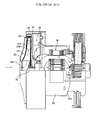
- Fig. 1 is a sectional view illustrating a conventional centrifugal blower for a vacuum cleaner.
- Fig. 2 is a plan view illustrating an impeller included in the conventional centrifugal blower.
- the conventional centrifugal blower for a vacuum cleaner includes an impeller housing 22 provided at a front end thereof with a suction port 22a, an impeller 24 rotatably installed in the impeller housing 22, a motor housing 23 coupled at a front end thereof to a rear end of the impeller housing 22, and provided at a rear end thereof with a plurality of discharge ports 23a, and a motor 30 installed in the motor housing 23, and connected to the impeller 24 via a rotating shaft 29 so as to rotate the impeller 24.
- the impeller 24 includes a pair of spaced covers, that is, a front cover 24a and a rear cover 24b, and a plurality of blades 24c installed between the front and rear covers 24a and 24b while extending to have a circumferentially curved configuration.
- Each blade 24c is fixed to the front and rear covers 24a and 24b at its front and rear ends, respectively.
- the fixing of each blade 24c to each cover 24a or 24b is achieved in a caulked fashion at four points.
- a disk member 27 is fixedly arranged at the rear of the impeller 24.
- Diffuser vanes 26 are formed at the front surface of the disk member 27 to feed air discharged from the outlet of the impeller 24 in a pressurized state, whereas guide vanes 28 are formed at the rear surface of the disk member 27 to guide the pressurized air fed by the diffuser vanes 26 to the motor 30.
- the impeller of the conventional centrifugal blower for a vacuum cleaner may be structurally instable when it is rotated at high speed, because the caulking positions of each blade 24c fixed to the front and rear covers 24a and 24b are set by simply quartering the length of the blade 24c, so that the stress applied to each caulked portion of the blade 24c during the high speed rotation of the impeller is locally concentrated without being uniformly dispersed.
- an object of the invention is to provide an impeller of a centrifugal blower for a vacuum cleaner in which the caulking positions of each blade mounted between front and rear covers are set so that a minimum stress is applied to each caulked portion of the blade during rotation of the impeller, thereby allowing the impeller to be structurally stable.
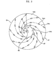
- Fig. 3 is a plan view illustrating an impeller included in a centrifugal blower for a vacuum cleaner in accordance with the present invention.
- Fig. 4 is a sectional view illustrating blades included in the impeller of the centrifugal blower according to the present invention.
- the impeller of the centrifugal blower includes a plurality of blades 54c mounted between a front cover 54a and a rear cover 54b while extending to have a curved configuration.
- Each blade 54c is fixed to the front and rear covers 54a and 54b at its front and rear ends, respectively.
- the fixing of each blade 54c to each cover 54a or 54b is achieved in a caulked fashion.
- the rear cover 54b is coupled to a motor (not shown) via a rotating shaft 60.
- Fig. 5 is a schematic view illustrating a blade configuration determined by a maximum camber position.
- a blade configuration is drawn using two arcs because there is a limitation in drawing a blade configuration using a single arc.
- a two arc method is mainly used, in which a blade configuration is drawn by two arcs having different diameters R1 and R2 in such a fashion that the contact point, at which the arcs are tangent to each other, corresponds a maximum camber position MCP, as shown in Fig. 5.
- the blade 54c has a reduced length while having an increased radius of curvature, ⁇ , at an increased value of the maximum camber position MCP. That is, the blade 54c has a relatively straight configuration while extending radially at the increased MCP value.
- the blade has a relatively small MCP value, that is, a relatively curved configuration
- bending stress is generated when a centrifugal force P is generated in a radial direction of the impeller 54 in accordance with rotation of the impeller 54.
- the blade has a relatively large MCP value, that is, a relatively straight configuration
- tensile stress is generated by the centrifugal force P.
- the stress applied to the blade is reduced as the MCP value is increased.
- the caulking positions of the blade 54c are set to correspond to positions spaced apart from the rotating shaft 60 by respective straight distances R1, R2, R3, and R4.
- R2 and R3 can be varied in accordance with the constants a and b respectively determined within predetermined ranges depending on the maximum camber position MCP of the blade 54c.
- the constants a and b are determined within respective ranges described in the following Table 1.
- Maximum Camber Position a b 0.4 0.7 to 0.8 0.3 to 0.4 0.5 0.7 to 0.8 0.3 to 0.4 0.6 0.7 to 0.8 0.2 to 0.3
- the caulking positions R1 and R4 are primarily determined. Thereafter, the caulking positions R2 and R3 are determined in accordance with the values of the caulking positions R1 and R4, and the constants a and b determined depending on the maximum camber position MCP.
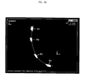
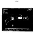
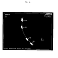
- Figs. 6a and 6b are graphs depicting caulking positions and stress distributions when the MCP value of the blade according to the present invention is 0.4, respectively.
- the stress applied between the blade 54c, which is made of aluminum, and each of the front and rear covers 54a and 54b, is uniformly dispersed around each of the caulking positions R1 to R4.
- a maximum stress of 493 MPa is applied to a stress concentration region M1.
- Figs. 7a and 7b are graphs depicting caulking positions and stress distributions when the MCP value of the blade according to the present invention is 0.5, respectively.
- the stress applied between the blade 54c, which is made of aluminum, and each of the front and rear covers 54a and 54b, is uniformly dispersed around each of the caulking positions R1 to R4.
- a maximum stress of 489 MPa is applied to a stress concentration region M2.
- Figs. 8a and 8b are graphs depicting caulking positions and stress distributions when the MCP value of the blade according to the present invention is 0.6, respectively.
- the stress applied between the blade 54c, which is made of aluminum, and each of the front and rear covers 54a and 54b, is uniformly dispersed around each of the caulking positions R1 to R4.
- a maximum stress of 362 MPa is applied to a stress concentration region M3.
- the maximum stress is more than the yield strength of general aluminum corresponding to 140 to 150 MPa, it has no influence on the total yield strength of the blade 54c because its stress concentration region M1, M2 or M3 corresponds to a very small portion of the blade 54c.
- the optimum caulking position for each of R1 to R4 between the front and rear covers 54a and 54b is also varied.
- the present invention provides an impeller of a centrifugal blower for a vacuum cleaner in which caulking positions of each blade are set in accordance with a specific equation established taking into consideration the length and maximum camber position of the blade, so as to cause a minimum stress to be applied to each caulked portion of the blade during rotation of the impeller, thereby being capable of securing a structural stability.
Landscapes
- Engineering & Computer Science (AREA)
- Mechanical Engineering (AREA)
- General Engineering & Computer Science (AREA)
- Structures Of Non-Positive Displacement Pumps (AREA)
Abstract
Description
each of the blades is caulked at positions spaced apart from a center of the impeller by respective distances of R1, R2, R3, and R4 expressed as follows:
| Maximum Camber Position | a | b |
| 0.4 | 0.7 to 0.8 | 0.3 to 0.4 |
| 0.5 | 0.7 to 0.8 | 0.3 to 0.4 |
| 0.6 | 0.7 to 0.8 | 0.2 to 0.3 |
Claims (8)
- An impeller of a centrifugal blower for a vacuum cleaner including a plurality of blades installed between front and rear covers while being curved, each of the blades being caulked to the front and rear covers at front and rear ends thereof, respectively, wherein
each of the blades is caulked at positions spaced apart from a center of the impeller by respective distances of R1, R2, R3, and R4 expressed as follows: - The impeller according to claim 1, wherein the constants "a" and "b" are determined by a maximum camber position of the blade.
- The impeller according to claim 1, wherein the constant "a" corresponds to 0.7 to 0.8, and the constant "b" corresponds to 0.3 to 0.4 when the blade has a maximum camber position value of not less than 0.35, but less than 0.45.
- The impeller according to claim 3, wherein the constant "a" corresponds to 0.73, and the constant "b" corresponds to 0.33 when the blade has a maximum camber position value of 0.4.
- The impeller according to claim 1, wherein the constant "a" corresponds to 0.7 to 0.8, and the constant "b" corresponds to 0.3 to 0.4 when the blade has a maximum camber position value of not less than 0.45, but less than 0.55.
- The impeller according to claim 5, wherein the constant "a" corresponds to 0.72, and the constant "b" corresponds to 0.33 when the blade has a maximum camber position value of 0.5.
- The impeller according to claim 1, wherein the constant "a" corresponds to 0.7 to 0.8, and the constant "b" corresponds to 0.2 to 0.3 when the blade has a maximum camber position value of not less than 0.55, but less than 0.65.
- The impeller according to claim 7, wherein the constant "a" corresponds to 0.75, and the constant "b" corresponds to 0.22 when the blade has a maximum camber position value of 0.6.
Applications Claiming Priority (2)
| Application Number | Priority Date | Filing Date | Title |
|---|---|---|---|
| KR2002003035 | 2002-01-18 | ||
| KR10-2002-0003035A KR100452359B1 (en) | 2002-01-18 | 2002-01-18 | The centrifugal blower's impeller for a cleaner |
Publications (2)
| Publication Number | Publication Date |
|---|---|
| EP1329185A2 true EP1329185A2 (en) | 2003-07-23 |
| EP1329185A3 EP1329185A3 (en) | 2003-08-20 |
Family
ID=19718615
Family Applications (1)
| Application Number | Title | Priority Date | Filing Date |
|---|---|---|---|
| EP02011833A Withdrawn EP1329185A3 (en) | 2002-01-18 | 2002-05-28 | Centifugal blower for vacuum cleaner |
Country Status (2)
| Country | Link |
|---|---|
| EP (1) | EP1329185A3 (en) |
| KR (1) | KR100452359B1 (en) |
Cited By (1)
| Publication number | Priority date | Publication date | Assignee | Title |
|---|---|---|---|---|
| US8998588B2 (en) | 2011-08-18 | 2015-04-07 | General Electric Company | Segmented fan assembly |
Families Citing this family (1)
| Publication number | Priority date | Publication date | Assignee | Title |
|---|---|---|---|---|
| KR100968818B1 (en) * | 2004-12-03 | 2010-07-08 | 현대자동차주식회사 | Protective cover structure of vehicle rear shock absorber |
Family Cites Families (9)
| Publication number | Priority date | Publication date | Assignee | Title |
|---|---|---|---|---|
| JPS5749097A (en) * | 1980-09-08 | 1982-03-20 | Hitachi Ltd | Impeller made of steel plate |
| JPS6045797A (en) * | 1983-08-22 | 1985-03-12 | Matsushita Electric Ind Co Ltd | centrifugal fan |
| JPS6146495A (en) * | 1984-08-11 | 1986-03-06 | Matsushita Electric Ind Co Ltd | Motor fan |
| US4735555A (en) * | 1985-10-01 | 1988-04-05 | Rexair, Inc. | Air blower assembly for vacuum cleaner |
| JPS6483892A (en) * | 1987-09-25 | 1989-03-29 | Matsushita Electric Industrial Co Ltd | Impeller for centrifugal blower |
| JP2537988B2 (en) * | 1988-09-07 | 1996-09-25 | 松下電器産業株式会社 | Electric blower |
| JPH0311195A (en) * | 1989-06-08 | 1991-01-18 | Shin Meiwa Ind Co Ltd | Pump device |
| JP3216988B2 (en) * | 1996-04-26 | 2001-10-09 | 株式会社日立製作所 | Vacuum cleaner and electric blower for vacuum cleaner |
| JPH1122694A (en) * | 1997-06-30 | 1999-01-26 | Hitachi Ltd | Centrifugal fan and electric blower and vacuum cleaner using the centrifugal fan |
-
2002
- 2002-01-18 KR KR10-2002-0003035A patent/KR100452359B1/en not_active Expired - Fee Related
- 2002-05-28 EP EP02011833A patent/EP1329185A3/en not_active Withdrawn
Cited By (1)
| Publication number | Priority date | Publication date | Assignee | Title |
|---|---|---|---|---|
| US8998588B2 (en) | 2011-08-18 | 2015-04-07 | General Electric Company | Segmented fan assembly |
Also Published As
| Publication number | Publication date |
|---|---|
| KR100452359B1 (en) | 2004-10-12 |
| EP1329185A3 (en) | 2003-08-20 |
| KR20030062693A (en) | 2003-07-28 |
Similar Documents
| Publication | Publication Date | Title |
|---|---|---|
| EP0072177B1 (en) | Impeller for centrifugal compressor | |
| US4531890A (en) | Centrifugal fan impeller | |
| US7008189B2 (en) | Centrifugal fan | |
| US5743710A (en) | Streamlined annular volute for centrifugal blower | |
| EP0971131A3 (en) | Centrifugal blower assembly for an automotive vehicle | |
| SE504976C2 (en) | Fiber pulp suspension pump with built-in vacuum pump | |
| CN110630540B (en) | Electric blower and electric dust collector | |
| US6695584B2 (en) | Turbo fan | |
| KR20210007929A (en) | Fan Motor and Manufacturing the Same | |
| EP1041287A3 (en) | Vacuum pump | |
| EP1329185A2 (en) | Centifugal blower for vacuum cleaner | |
| EP1325702B1 (en) | Centrifugal blower for vacuum cleaner | |
| US20060062669A1 (en) | Blower | |
| KR20210033452A (en) | Fan Motor | |
| KR102334621B1 (en) | Fan Motor | |
| JP2010270750A (en) | Electric blower, vacuum cleaner equipped with the same, and method for manufacturing the same | |
| US20240280110A1 (en) | Fan for handheld blower | |
| KR100437035B1 (en) | Centrifugal fan of vacuum cleaner | |
| JPH08200290A (en) | Centrifugal blower | |
| JPH0914192A (en) | Electric blower and vacuum cleaner | |
| JPH0474560B2 (en) | ||
| JPH08193595A (en) | Electric blower for vacuum cleaner | |
| JP2757501B2 (en) | Rotating fan of electric blower | |
| KR100572863B1 (en) | Turbo Fans for Air Conditioners | |
| JPS62291495A (en) | Centrifugal multistage blower |
Legal Events
| Date | Code | Title | Description |
|---|---|---|---|
| PUAI | Public reference made under article 153(3) epc to a published international application that has entered the european phase |
Free format text: ORIGINAL CODE: 0009012 |
|
| PUAL | Search report despatched |
Free format text: ORIGINAL CODE: 0009013 |
|
| AK | Designated contracting states |
Designated state(s): AT BE CH CY DE DK ES FI FR GB GR IE IT LI LU MC NL PT SE TR |
|
| AX | Request for extension of the european patent |
Extension state: AL LT LV MK RO SI |
|
| AK | Designated contracting states |
Designated state(s): AT BE CH CY DE DK ES FI FR GB GR IE IT LI LU MC NL PT SE TR |
|
| AX | Request for extension of the european patent |
Extension state: AL LT LV MK RO SI |
|
| 17P | Request for examination filed |
Effective date: 20030912 |
|
| AKX | Designation fees paid |
Designated state(s): DE FR GB IT |
|
| 17Q | First examination report despatched |
Effective date: 20070809 |
|
| STAA | Information on the status of an ep patent application or granted ep patent |
Free format text: STATUS: THE APPLICATION IS DEEMED TO BE WITHDRAWN |
|
| 18D | Application deemed to be withdrawn |
Effective date: 20100216 |