EP1328353B1 - Verbesserte brandbekämpfungsdüse und verfahren, das druckregelung, chemische und abführmerkmale beinhaltet - Google Patents
Verbesserte brandbekämpfungsdüse und verfahren, das druckregelung, chemische und abführmerkmale beinhaltet Download PDFInfo
- Publication number
- EP1328353B1 EP1328353B1 EP00966967A EP00966967A EP1328353B1 EP 1328353 B1 EP1328353 B1 EP 1328353B1 EP 00966967 A EP00966967 A EP 00966967A EP 00966967 A EP00966967 A EP 00966967A EP 1328353 B1 EP1328353 B1 EP 1328353B1
- Authority
- EP
- European Patent Office
- Prior art keywords
- nozzle
- pressure
- flow rate
- fluid
- discharge orifice
- Prior art date
- Legal status (The legal status is an assumption and is not a legal conclusion. Google has not performed a legal analysis and makes no representation as to the accuracy of the status listed.)
- Expired - Lifetime
Links
- 238000000034 method Methods 0.000 title claims abstract description 11
- 239000000126 substance Substances 0.000 title description 14
- 239000012530 fluid Substances 0.000 claims description 63
- 239000006260 foam Substances 0.000 claims description 18
- 239000012141 concentrate Substances 0.000 claims description 9
- 238000007667 floating Methods 0.000 claims description 9
- 230000008685 targeting Effects 0.000 claims 1
- XLYOFNOQVPJJNP-UHFFFAOYSA-N water Substances O XLYOFNOQVPJJNP-UHFFFAOYSA-N 0.000 description 12
- 230000001105 regulatory effect Effects 0.000 description 7
- 206010019233 Headaches Diseases 0.000 description 5
- 239000000843 powder Substances 0.000 description 5
- 230000008901 benefit Effects 0.000 description 4
- 230000005465 channeling Effects 0.000 description 2
- 230000002093 peripheral effect Effects 0.000 description 2
- 230000004044 response Effects 0.000 description 2
- 230000001629 suppression Effects 0.000 description 2
- 238000011144 upstream manufacturing Methods 0.000 description 2
- 229910001369 Brass Inorganic materials 0.000 description 1
- 239000000654 additive Substances 0.000 description 1
- 230000000996 additive effect Effects 0.000 description 1
- 230000003466 anti-cipated effect Effects 0.000 description 1
- 230000000740 bleeding effect Effects 0.000 description 1
- 239000010951 brass Substances 0.000 description 1
- 230000008859 change Effects 0.000 description 1
- 231100000481 chemical toxicant Toxicity 0.000 description 1
- 230000000694 effects Effects 0.000 description 1
- 238000005516 engineering process Methods 0.000 description 1
- 239000007788 liquid Substances 0.000 description 1
- 239000000463 material Substances 0.000 description 1
- 230000007246 mechanism Effects 0.000 description 1
- 238000011084 recovery Methods 0.000 description 1
- 230000000630 rising effect Effects 0.000 description 1
- 231100000331 toxic Toxicity 0.000 description 1
- 230000002588 toxic effect Effects 0.000 description 1
- 239000003440 toxic substance Substances 0.000 description 1
- 238000013022 venting Methods 0.000 description 1
- 239000002351 wastewater Substances 0.000 description 1
- 238000009736 wetting Methods 0.000 description 1
Images



Classifications
-
- A—HUMAN NECESSITIES
- A62—LIFE-SAVING; FIRE-FIGHTING
- A62C—FIRE-FIGHTING
- A62C31/00—Delivery of fire-extinguishing material
- A62C31/02—Nozzles specially adapted for fire-extinguishing
- A62C31/05—Nozzles specially adapted for fire-extinguishing with two or more outlets
- A62C31/07—Nozzles specially adapted for fire-extinguishing with two or more outlets for different media
-
- A—HUMAN NECESSITIES
- A62—LIFE-SAVING; FIRE-FIGHTING
- A62C—FIRE-FIGHTING
- A62C31/00—Delivery of fire-extinguishing material
- A62C31/02—Nozzles specially adapted for fire-extinguishing
-
- A—HUMAN NECESSITIES
- A62—LIFE-SAVING; FIRE-FIGHTING
- A62C—FIRE-FIGHTING
- A62C31/00—Delivery of fire-extinguishing material
- A62C31/02—Nozzles specially adapted for fire-extinguishing
- A62C31/12—Nozzles specially adapted for fire-extinguishing for delivering foam or atomised foam
-
- A—HUMAN NECESSITIES
- A62—LIFE-SAVING; FIRE-FIGHTING
- A62C—FIRE-FIGHTING
- A62C5/00—Making of fire-extinguishing materials immediately before use
- A62C5/02—Making of fire-extinguishing materials immediately before use of foam
Definitions
- the invention relates to fire fighting and fire preventing nozzles and more particularly to nozzles for extinguishing or preventing large industrial grade fires including flammable liquid fires and/or for nozzles for vapor suppression, and includes improvements in pressure regulating, educting and chemical discharge features, as well as methods of use.
- Prior patents relevant to the instant invention include: (1) U. S. Patent No. 4,640 461 (Williams ) directed to a self educting foam fog nozzle; (2) U.S. Patent No. 5,779, 159 (Williams ) directed to a peripheral channeling additive fluid nozzle; and (3) U.S. Patent Nos. 5,275,243 ; 5,167,285 and 5,312,041 (Williams ) directed to a chemical and fluid or duel fluid ejecting nozzle. Also relevant is the prior art of automatic nozzles, including (4) U.S. Patent Nos. 5,312,048 ; 3,684,192 and 3,863,844 to McMUian /Task Force Tips and U.S.
- Maintaining a constant discharge pressure from a nozzle tends to yield a constant range and "authority" for the discharge while allowing the nozzle flow rate to absorb variations in head pressure, as it were.
- a fixed fire fighting nozzle is particularly useful if it self regulates to discharge at an approximately constant or targeted pressure.
- the discharge pressure tends to govern what is referred to as the "authority" of the discharge stream and to a certain extent the stream's range.
- a constant discharge pressure comes closer to a consistent delivery of a stream at a fixed range.
- a self-regulating nozzle may be useful in a fiked protection system that includes nozzles permanently stationed around locales subject to the leakage of toxic chemicals.
- a permanently stationed configuration of constant pressure nozzles possibly under remote control, could be activated to provide a predesigned curtain of water/fog to contain and suppress any toxic vapors.
- Water/fog created with approximately constant range and authority, while operating under conditions of varying head pressure, will more reliably curtain a preselected region from a fixed locale.
- nozzles are structured to deliver a pre-set gallons-per-minute flow rate, assuming a nominal head pressure, such as 6.89 Bar (100 psi) at the nozzle. As the head pressure actually available to a nozzle in an emergency can vary, flow rate remains more consistent in such designs than range. Alternately structuring a nozzle to target and regulate discharge pressure lets flow rate vary with variations in delivered pressure while keeping range more constant.
- the present invention discloses an improved pressure regulating nozzle designed to effectively discharge a fire extinguishing fluid at a pre-selected discharge pressure and range, up to a targeted flow rate, and thereafter to maintain relatively constant flow rate while discharge pressure and range are allowed to increase .
- a preselected discharge pressure for example, would likely be approximately 6.89 Bar (100 psi), but the preselected pressure could vary, and might more optimally be selected to be approximately 8.27 Bar (120 psi)
- a targeted flow rate is selected. This selection of targeted flow rate need only be approximate.
- the inventive design combines the benefit value of maintaining range at low supply pressures while maintaining flow rate at higher supply pressures, thereby accommodating minimum range requirements on the one hand while more easily accommodating self-educting features for foam concentrates and a capacity to throw fluid chemicals such as dry powder on the other hand, where possible.
- the invention includes enhanced eductive techniques, for both peripheral and central channeling, which enhanced eduction can be particularly helpful in automatic nozzles or when throwing chemicals such as dry powder.
- a typical fire fighting nozzle may be designed to be adjusted to operate over a range offlows, such as 1.89 to 7.57 m 3 per minute (500 gallons-per-minuteto 2000 gallons per-minute), given a certain discharge pressure (typically assumed to be around 6.89 Bar (100 psi)).
- nozzle design incorporates a self-adjusting baffle or the like proximate the nozzle discharge.
- the baffle is structured in combination with the nozzle body to "squeeze down" on the effective size of the discharge orifice.
- the baffle When pressure builds up at the baffle, sensed directly or indirectly, to reach or exceed a preselected pressure, the baffle is structured to cease squeezing down and, if necessary, to shift to enlarge the effective size ofthe nozzle discharge orifice. Enlargement continues, in general, until the discharge pressure reduces to the selected value. Adjustments in the size of the discharge port cause flow rate to vary but the discharge tends to have constant "authority" and range.
- a fire fighting nozzle defines a conduit for a fire fighting fluid that terminates in a discharge orifice.
- the fire fighting fluid is usually water, and while it may be treated and discussed as water herein, it should be understood that nozzle technology is applicable to various fire fighting fluids.
- the conduit and discharge orifice structure are typically designed in combination to recover, to the extent practical, fire fighting fluid pressure available from the fluid source. Recovery of pressure affects range.
- nozzle body conduits and discharge orifices may be designed to define an effective, or practical, flow window.
- a "two and one-half inch" (63.5 mm) nozzle might be adjustable to effectively flow between 0.57 and 2.27 m 3 per minute (150 GPM and 600 GPM) while a "sixteen inch” (0.41 m) nozzle might be adjustable to effectively flow between 15.14 and 60.56 m 3 per minute (4,000 GPM and 16,000 GPM) both being affected by variations in supply pressure or quantity.
- An adjustable discharge orifice is designed to be adjusted within a range of flow effectiveness of a nozzle body. Fluid flow rate through the nozzle may vary within a nozzle's effective flow window, again taking into account variations in source supply and pressure.
- Minimum limits on an effective flow window include a minimum effective "gap" size, or a minimum effective width of a typically annular discharge orifice. Below a certain "gap" size the thickness ofthe wall ofwater discharged diminishes such that the water wall tends to disintegrate and nozzle throw performance suffers. On the other end, a "gap" can get so large that the fixed conduit bore structure itself governs throw. There is thus a practical limit to the flow of water that can be efficiently flowed through a nozzle bore.
- adjustable discharge orifices may be traditionally designed in terms of an adjustable baffle within a conduit
- any element of a nozzle structure defining at least in part the discharge orifice, including an outer wall portion could be an adjustable element.
- a given conduit and discharge orifice contribute to defining a "k" factor for a nozzle.
- Automatic nozzles have automatically adjustable discharge orifices.
- Automatically adjustable discharge orifices are typically designed to maintain a selected discharge pressure, such as 6.89 Bar (100 psi).
- a biasing means structured to adjust the discharge orifice (sometimes referred to as the "gap") until the sensed discharge pressure is approximately the preselected discharge pressure.
- a discharge orifice or gap is narrowed or widened so that the sensed discharge pressure is approximately the selected discharge pressure.
- a relatively constant flow rate of the fluid stream is an advantage, as it allows a metering device on the foam concentrate to be set. Further, a relatively constant flow rate with a high discharge pressure may be desired in some circumstances. E.g. high pressure helps some concentrate to create a better foam. In a nozzle that discharges a chemical, such as a dry powder, within a fire fighting fluid, it may be desirable to limit fluid flow rate to avoid unnecessary wetting of the powder. Further, nozzles that adjust without limitation to produce a selected discharge pressure can waste water if there is a limited supply of water.
- a relatively constant flow rate from a nozzle can be an advantage in several situations, but if the supply pressure is weak, or if a nozzle is set at a fixed distance from a fire, a relatively constant pressure may be an advantage. (Constant pressure tends to maintain range for the nozzle even though flow rate may vary). Within the duration of one fire, the relative importance of constant pressure and of constant flow rate can shift.
- the hybrid, selectively automatic nozzle of the instant invention provides the best of two worlds.
- the adjustable stop (or any other such adjustable means) can be set so that an automatically adjustable discharge orifice is provided, as in an automatic nozzle, for flow rates up to a given point (in a nozzle's effective flow window). If supply pressure goes low, range can be maintained. However, if a targeted fluid flow rate within the nozzle is reached, a stop or the like causes the discharge orifice to cease adjusting. Now discharge pressure rises with supply pressure but fluid flow rate tends to remain approximately constant (again, rising only in proportion to the square root of the pressure). Metering foam concentrate in a preselected proportion is thus more reliable, with fixed flow rate.
- the location of the Allenbaugh '279 adjustable stop means, upstream in a nozzle as opposed to downstream of the discharge orifice, is incompatible with fire fighting fog and foam nozzle designs that maximize range, such as nozzles for fighting large industrial fires, when considerations of heat and safety limit the staging of the nozzle close to the fire. Nozzles structured to maximize range minimize the interference with a laminar flow through the nozzle. Allenbaugh's upstream adjustable stop means interferes with laminar flow through the nozzle.
- the invention includes a selectively automatic fire fighting nozzle comprising a nozzle body having a conduit terminating in a discharge orifice.
- the discharge orifice is automatically adjustable within a range.
- the nozzle body includes a stop or the like, adjustable to limit a range of automatic adjustment of the orifice.
- This stop could be any adjustable means, simple or complex, for limiting the range of automatic adjustment of the orifice.
- the stop or adjustable means is located upon the nozzle body and divides a nozzle effective flow window such that the nozzle flows at variable flow rate/constant pressure for flow rates up to a targeted flow rate, and flows at variable pressure/constant flow rate as long as the targeted flow rate is needed.
- the invention includes a method for operating an automatic fire fighting nozzle comprising (approximately) maintaining a selected fire fighting fluid discharge pressure for fluid flowing through the nozzle for flow up to a targeted rate and allowing discharge pressure to rise above selected discharge pressure as long as the targeted flow rate is reached.
- the selectively automatic fire fighting nozzle is also preferably a self-educting foam fog nozzle and even more preferably, a self-metering self-educting foam fog nozzle.
- a nozzle having an "adjustable" baffle in order to discharge fire extinguishing fluid at a selected pressure uses a biasing means opposing a natural movement of an adjustable baffle outwards in response to fluid pressure, which outward movement tends to open the effective size of a discharge orifice.
- the biasing means biases with a backward force equal to the force of the desired or selected fluid pressure upon the forward baffle surfaces.
- baffle forward movement balances against baffle backward bias pressure at the selected pressure.
- Forward baffle surfaces are surfaces that the baffle presents to the fire extinguishing fluid moving through and out of the discharge port
- the biasing force could be provided by a spring that, over the adjustment range of the baffle between its end points, which may be no more than approximately one half of an inch (12.7 mm) presents an essentially constant biasing force at the selected pressure.
- the selected pressure might well be 6.89 Bar (100 psi).
- an adjustable bafflehead could be designed defining a chamber within the bafflehead and presenting forward and backward surfaces against which the primary fire extinguishing fluid could act. It is understood that the chamber defined within the bafflehead would have means for permitting a portion of the fire extinguishing fluid to enter the chamber. In such designs the effective backward pressure surface area would usually exceed the effective forward pressure surface area of the baffle.
- the fluid pressure within the baffle is expected to be at least slightly less than the pressure exerted on forward facing baffle surfaces, Such tends to counter the fact that the backward pressure surface area presented to the fluid within the baffle, at least in preferred embodiments herein, exceeds the forward pressure surface area presented on the baffle. In such manner the fluid within the baffle acts against a greater surface area and, although lower in value, can potentially drive the baffle backwards against the flow of fluid through the nozzle. Anticipating the difference between the pressures, without and within the baffle, at different source pressures, and anticipating the difference in the effective areas presented to the fluid pressures at different head pressures and flow rates, leads to a design for a "balanced baffle" at a targeted fluid pressure.
- a relief valve vents fluid pressure from one or the other side of the baffle, preferably from within the baffle chamber, when fluid pressure varies from target pressure. Such venting typically causes the baffle to move, as in an illustrated case, outward toward one of the baffle location end points. A movement outward or toward the outward end direction will cause a decrease in the fluid pressure upon the baffle. Such decrease in fluid pressure could cause the relief valve to again close, permitting again the buildup of fluid pressure upon the back side of the baffle.
- the build up of fluid pressure upon the back side of the baffle should help adjust the baffle toward a balanced position where the fluid pressure on the forward surfaces of the baffle balances the fluid pressure on backward surfaces of the baffle, including taking into account other biasing elements such as a continuously "bleeding" relief valve and any springs utilized in the design.
- the relief valves illustrated sense either rather directly the primary fire extinguishing fluid pressure presented to forward baffle surface areas in the nozzle or sense more indirectly a more secondary fluid pressure generated within a chamber within the baffle.
- the difference between such designs, or other designs that could occur to those of skill in the art, can largely be a matter of design choice and simplicity of engineering.
- One function selected for a reliefvalve could be to assist in achieving the situation where a balanced pressure position is consistently approached from the same direction, which could either be the moving outwardly or the moving inwardly the baffle. Such a design may facilitate engineering a higher degree of accuracy around the balance point with less hunting and greater speed in achieving balance.
- the present invention as in the referenced and incorporated applications, also teaches improved self educting features that are particularly helpful and useful in a pressure regulating nozzle, as well as enhanced educting and pressure regulating designs that are useful when throwing fluid chemical such as dry powder, with or without an automatic nozzle.
- a self-adjusting automatic feature depends upon an adjustable baffle that adjusts, at least in significant part, in response to primary fire fighting fluid pressure presented both to a forward and a reverse side of a baffle surface.
- the baffle operates at least in part as a two-way piston seeking a balanced pressure position.
- the nozzle fluid provides a fluid pressure to act against both sides of the baffle.
- the pressure acting in the reverse direction will be at least a function of the forward pressure.
- the reverse pressure surface of the baffle will be larger than the forward pressure surface of the baffle. It is recognized that the forward pressure surface of the baffle may in fact change and be a function of pressure and fluid flow through the nozzle and baffle design and nozzle size.
- preferred embodiments utilize at least one relief valve.
- Preferred embodiments further utilize a relief valve to relieve pressure in the reverse direction.
- the area ofthe reverse pressure surface is greater than the area of the forward pressure surface.
- the relief valve when the relief valve is closed, in general, the reverse pressure times the area of the reverse pressure surface will be greater than the forward pressure times the area of the forward baffle surface. This will dictate that for significant values of forward pressure the nozzle is biased closed.
- one or more relief valves begin to open relieving pressure on the reverse side of the baffle and allowing the bafflehead to balance onto open and adjust outward.
- the relief valve builds in a degree of adjustability such that the relief valve can select a partially opened position and settle upon such position without undue hunting and wherein the target pressure times the forward surface at the target pressure equals the reverse pressure times the reverse pressure surface area taking into account the degree of openness of the relief valve system
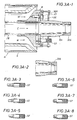
- Figures 1A, 1B , 1C , 2A. 2B , 3A and 3B illustrate embodiments of the instant invention, a selectively automatic fire fighting nozzle.
- the embodiment of Figures 1A-C , 2A, B and 3A herein are analogous to the embodiments of Figure 3A , Figure 3D, Figures 4C, 4D, 5A, 5B, 5C and 6, of the applications referenced and incorporated above.
- the instant Figures 1A, 1B and 1C illustrate a pilot valve 42 situated in piston 26. Floating bafflehead B moves outward, as controlled by pilot valve 42, to the right to widen gap 220.
- Figure 1A illustrates a gap 220 suitable to flow 3.79 m 3 per minute (1,000 GPM) while Figure 1B illustrates a gap 220 suitable to flow 7.57 m 3 per minute (2,000 GPM) and Figure 1C illustrates a gap 220 suitable to flow 15.14 m 3 per minute (4,000 GPM).
- Water W flows through the nozzle body in Figures 1 from left to right.
- Foam concentrate FC or chemical C flows through the foam/chemical tube 28.
- New in Figures 1A, 1B and 1C as opposed to Figures 3-6 of the prior applications, is flow stop ST. The flow stop is shown set for a "4,000 GPM" (15.14 m 3 per minute) gap 220 size, illustrated in Figure 1C .
- flow stop ST is conveniently affixed to a portion of piston 26.
- floating bafflehead B When an inside surface of floating bafflehead B reaches or contacts flow stop ST, floating bafflehead B ceases to further adjust outward or to the right. Ifwater supply and pressure increases, the gap will remain as in Figure 10C. Flow rate will remain approximately 15.14 m 3 per minute (4,000 GPM) while discharge pressure will rise. Pilot valve 42 is presumed to be set at some pre-selected pressure such as 6.89 Bar (100 psi).
- pilot valve 42 leaks fluid from the baffle chamber and floating bafflehead B moves out, or downstream, widening the gap created between the floating bafflehead B and the nozzle body.
- pattern control sleeve S is shown, as is customary for a fog nozzle. For clarity the sleeve is always shown in the "fog" pattern position.
- Figures 2A and 2B illustrate embodiments similar to Figures 1A-1C .
- Figures 2A, 2B , 3A and 3B show a flood plate 300 attached by pins 308 to floating bafflehead B.
- the flood plate can be adjusted for a foam application, as in Figures 2A and 3B .
- plug 302 is attached to flood plate 300.
- the nozzle can be adjusted for a hydrochemical application, as in Figures 2B and 3A , in which case chemical extension tube 304 is affixed to flood plate 300.
- Adjustable chemical flow chokes 306 are usually provided with a chemical extension tube 304.
- the nozzle embodiment of Figures 2B and 3A is thus adapted to throw not only water but dry chemical.
- the nozzle embodiment of Figure 2A is adapted to throw not only water but foam concentrate.
- a flow stop ST illustrated in 3A and 3B is shown achieving a full closed position for the nozzle.
- Alternate flow stops ST can installed, by the design of the preferred embodiment to permit bafflehead B to move out into the positions illustrated in Figures 1A, 1B , 1C , 3A and 3B .
- a set of stops ST are provided, each stop with a different shank length to govern a different gap size.
- one stop could be provided adjustable as by screwing.
- Other equivalent means could be utilized to place a limit on a floating bafflehead or the like in its forward or downstream movement.
- the nozzle show in Figures 2A and 3B are adaptable to be used with a self metering self-educting nozzle as disclosed more fully in the above referenced and incorporated patent application.
- the adjustable nozzle would be presumed to set to target a preselected discharge pressure such as 6.89 Bar (100 psi).
- a preselected discharge pressure such as 6.89 Bar (100 psi).
- the operator as in the preferred embodiment of Figures 3 and 3B , will select a stop that approximately targets a given flow rate.
- the operator will affix the stop in the position provided in the fixed piston.
- the floating bafflehead will then maintain a fixed pressure until the bafflehead is stopped by abutting the end of the flow stop that extends through the piston into the baffle chamber. Thereafter, if supply pressure rises and supply flow is adequate, the discharge pressure at the nozzle will rise. The gap will remain constant and the flow rate will remain approximately constant.
Landscapes
- Health & Medical Sciences (AREA)
- Public Health (AREA)
- Business, Economics & Management (AREA)
- Emergency Management (AREA)
- Fire-Extinguishing By Fire Departments, And Fire-Extinguishing Equipment And Control Thereof (AREA)
- Nozzles (AREA)
- Fire-Extinguishing Compositions (AREA)
Claims (8)
- Eine selektiv automatische Feuerbekämpfungsdüse, die einen Körperabschnitt der Düse aufweist, der eine Feuerbekämpfungsfluidleitung, die in einer einstellbaren Ausstoßöffnung (220) endet, definiert, wobei die einstellbare Ausstoßöffnung zumindest teilweise durch Elemente (B), die sich über einen verfügbaren Bereich automatisch relativ einstellen, definiert ist, gekennzeichnet durch eine Stoppvorrichtung (ST), die mit dem Körper stromabwärts von der einstellbaren Ausstoßöffnung (220) verbunden ist, wobei die Stoppvorrichtung einstellbar ist, um innerhalb des verfügbaren Bereichs den Bereich der automatischen relativen Einstellung zwischen den die Öffnung definierenden Elementen weiter zu begrenzen.
- Düse gemäß Anspruch 1, wobei durch einen effektiven Einstellungsbereich der einstellbaren Ausstoßöffnung ein Flussfenster definiert ist und wobei die Stoppvorrichtung (ST) einstellbar auf dem Düsenkörper befindlich ist, um das Flussfenster zu teilen, so dass die Düse in einem ersten Teil des Flussfensters mit einer variierenden Durchflussrate und einem annähernd konstanten Druck fließt und in einem zweiten Teil des Flussfensters mit einem variierenden Druck und einer relativ konstanten Durchflussrate fließt.
- Düse gemäß Anspruch 1 oder Anspruch 2, wobei die Stoppvorrichtung (ST) die Vorwärtsbewegung einer schwebenden Prallfläche (B) begrenzt.
- Düse gemäß einem der Ansprüche 1 bis 3, wobei die Düse eine selbstansaugende Schaumnebeldüse ist.
- Düse gemäß Anspruch 4, wobei die Düse eine selbst abmessende selbstansaugende Schaumnebeldüse ist.
- Ein Verfahren zum Betreiben einer automatischen Feuerbekämpfungsdüse, die eine automatisch variierende Ausstoßöffnung (220) aufweist, wobei die Düse variierendem Versorgungsdruck unterliegt, wobei das Verfahren Folgendes umfasst: das Anstreben einer Durchflussrate, die geringer als eine maximal mögliche Durchflussrate ist, für die bei einem Standardversorgungsdruck betriebene Düse, wobei die maximal mögliche Durchflussrate einer durch die Düsenstruktur bereitgestellten maximalen Öffnung der Ausstoßöffnung (220) entspricht, und das annähernde Beibehalten eines ausgewählten Feuerbekämpfungsfluidausstoßdrucks für das durch die Düse fließende Feuerbekämpfungsfluid für Fluiddurchflussraten bis zu annähernd der angestrebten Durchflussrate, wobei die Verbesserung durch Folgendes gekennzeichnet ist: Ermöglichen, dass der Fluidausstoßdruck über den ausgewählten Ausstoßdruck steigt, während die Fluiddurchflussrate beim Erreichen der angestrebten Durchflussrate durch das Begrenzen der Einstellung der automatisch einstellbaren Ausstoßöffnung (220) (annähernd) innerhalb eines effektiven Einstellungsbereichs der Öffnung gehalten wird, einschließlich des Einstellens einer stromabwärts der einstellbaren Ausstoßöffnung (220) befindlichen Stoppvorrichtung (ST).
- Verfahren gemäß Anspruch 6, das das Ansaugen von Schaumkonzentrat (FC) in die Düse umfasst.
- Verfahren gemäß Anspruch 7, das das einstellbare Abmessen von Schaumkonzentrat (FC) in die Düse, während die Ausstoßöffnung (220) eingestellt wird, umfasst.
Applications Claiming Priority (1)
| Application Number | Priority Date | Filing Date | Title |
|---|---|---|---|
| PCT/US2000/026568 WO2002026393A1 (en) | 2000-09-27 | 2000-09-27 | Improved fire fighting nozzle and method including pressure regulation, chemical and eduction features |
Publications (3)
| Publication Number | Publication Date |
|---|---|
| EP1328353A1 EP1328353A1 (de) | 2003-07-23 |
| EP1328353A4 EP1328353A4 (de) | 2008-05-14 |
| EP1328353B1 true EP1328353B1 (de) | 2010-09-08 |
Family
ID=21741816
Family Applications (1)
| Application Number | Title | Priority Date | Filing Date |
|---|---|---|---|
| EP00966967A Expired - Lifetime EP1328353B1 (de) | 2000-09-27 | 2000-09-27 | Verbesserte brandbekämpfungsdüse und verfahren, das druckregelung, chemische und abführmerkmale beinhaltet |
Country Status (11)
| Country | Link |
|---|---|
| EP (1) | EP1328353B1 (de) |
| JP (1) | JP4889911B2 (de) |
| CN (1) | CN1455706A (de) |
| AT (1) | ATE480304T1 (de) |
| AU (2) | AU7723500A (de) |
| CA (1) | CA2423593C (de) |
| DE (1) | DE60044949D1 (de) |
| ES (1) | ES2350913T3 (de) |
| MX (1) | MXPA03002675A (de) |
| NO (1) | NO20031169L (de) |
| WO (1) | WO2002026393A1 (de) |
Families Citing this family (5)
| Publication number | Priority date | Publication date | Assignee | Title |
|---|---|---|---|---|
| FR2871389B1 (fr) * | 2004-06-11 | 2006-09-22 | St Mihiel Sas Soc Par Actions | Lance d'incendie a debit de fluide constant |
| RU2424836C1 (ru) * | 2010-01-20 | 2011-07-27 | Закрытое Акционерное Общество "Инженерный Центр Пожарной Робототехники "Эфэр" | Пожарный монитор с круговым осциллятором |
| CN103990243A (zh) * | 2013-05-21 | 2014-08-20 | 福州大学 | 持压灭火喷头及实现灭火喷头压力均衡的方法 |
| WO2021137179A1 (en) * | 2020-01-03 | 2021-07-08 | Tyco Fire Products Lp | Adjustable fog jet nozzle |
| CN113134189A (zh) * | 2020-01-19 | 2021-07-20 | 山东昊星洁士新材料科技有限公司 | 一种喷射混合消防装置 |
Citations (1)
| Publication number | Priority date | Publication date | Assignee | Title |
|---|---|---|---|---|
| US4469279A (en) * | 1982-08-30 | 1984-09-04 | Premier Industrial Corporation | Constant pressure nozzle with selective volume limit control |
Family Cites Families (9)
| Publication number | Priority date | Publication date | Assignee | Title |
|---|---|---|---|---|
| US3539112A (en) * | 1969-04-16 | 1970-11-10 | Elkhart Brass Mfg Co | Fire hose nozzle with automatic volume adjustment |
| US3684192A (en) * | 1970-06-22 | 1972-08-15 | Fire Task Force Innovations In | Constant pressure, variable flow nozzle |
| JPS5622930Y2 (de) * | 1978-06-26 | 1981-05-29 | ||
| JPS61142065U (de) * | 1985-02-26 | 1986-09-02 | ||
| US4768718A (en) * | 1987-04-10 | 1988-09-06 | Slautterback Corporation | Nozzle with internal valve for applying viscous fluid material |
| US5167285A (en) * | 1991-03-21 | 1992-12-01 | Cca, Inc. | Dry powder and liquid method and apparatus for extinguishing fire |
| US5312048A (en) * | 1993-03-25 | 1994-05-17 | Task Force Tips, Inc. | Regulating nozzle with adjustable effective area baffle |
| US5330105A (en) * | 1993-03-26 | 1994-07-19 | Valkyrie Scientific Proprietary, L.C. | Aspirating nozzle and accessory systems therefor |
| JPH1147301A (ja) * | 1997-08-01 | 1999-02-23 | Ishikawajima Shibaura Mach Co Ltd | 放水銃 |
-
2000
- 2000-09-27 WO PCT/US2000/026568 patent/WO2002026393A1/en not_active Ceased
- 2000-09-27 DE DE60044949T patent/DE60044949D1/de not_active Expired - Lifetime
- 2000-09-27 CA CA2423593A patent/CA2423593C/en not_active Expired - Fee Related
- 2000-09-27 MX MXPA03002675A patent/MXPA03002675A/es active IP Right Grant
- 2000-09-27 ES ES00966967T patent/ES2350913T3/es not_active Expired - Lifetime
- 2000-09-27 CN CN00819911.6A patent/CN1455706A/zh active Pending
- 2000-09-27 AT AT00966967T patent/ATE480304T1/de not_active IP Right Cessation
- 2000-09-27 AU AU7723500A patent/AU7723500A/xx active Pending
- 2000-09-27 JP JP2002530214A patent/JP4889911B2/ja not_active Expired - Lifetime
- 2000-09-27 AU AU2000277235A patent/AU2000277235B2/en not_active Ceased
- 2000-09-27 EP EP00966967A patent/EP1328353B1/de not_active Expired - Lifetime
-
2003
- 2003-03-14 NO NO20031169A patent/NO20031169L/no unknown
Patent Citations (1)
| Publication number | Priority date | Publication date | Assignee | Title |
|---|---|---|---|---|
| US4469279A (en) * | 1982-08-30 | 1984-09-04 | Premier Industrial Corporation | Constant pressure nozzle with selective volume limit control |
Also Published As
| Publication number | Publication date |
|---|---|
| DE60044949D1 (de) | 2010-10-21 |
| WO2002026393A1 (en) | 2002-04-04 |
| NO20031169D0 (no) | 2003-03-14 |
| JP4889911B2 (ja) | 2012-03-07 |
| MXPA03002675A (es) | 2004-12-03 |
| CN1455706A (zh) | 2003-11-12 |
| AU7723500A (en) | 2002-04-08 |
| CA2423593C (en) | 2010-09-14 |
| JP2004509716A (ja) | 2004-04-02 |
| ES2350913T3 (es) | 2011-01-28 |
| AU2000277235B2 (en) | 2006-04-27 |
| EP1328353A4 (de) | 2008-05-14 |
| ATE480304T1 (de) | 2010-09-15 |
| EP1328353A1 (de) | 2003-07-23 |
| NO20031169L (no) | 2003-05-14 |
| CA2423593A1 (en) | 2002-04-04 |
Similar Documents
| Publication | Publication Date | Title |
|---|---|---|
| US7048207B2 (en) | Fire fighting nozzle and method including pressure regulation, chemical and eduction features | |
| US8002203B2 (en) | Fire fighting nozzle and method including pressure regulation, chemical and eduction features | |
| US9259746B2 (en) | Adjustable smooth bore nozzle | |
| WO2013033079A1 (en) | Fluid mixing and delivery system | |
| US20100314137A1 (en) | Fire fighting foam proportioning devices and systems having improved low flow performance | |
| EP1328353B1 (de) | Verbesserte brandbekämpfungsdüse und verfahren, das druckregelung, chemische und abführmerkmale beinhaltet | |
| US9488989B2 (en) | Flow rate controller for high flow rates and high pressure drops | |
| EP1163931A2 (de) | System zum selbsttätigen Dosieren von Schaumkonzentrat in einem Rohr mit variabler Durchflussrate für Brandbekämpfungsflüssigkeit | |
| AU2000277235A1 (en) | Improved fire fighting nozzle and method including pressure regulation, chemical and eduction features | |
| US7784709B1 (en) | Fire fighting nozzle and method including pressure regulation, chemical and eduction features | |
| US9266125B2 (en) | Nozzle with combination presure-relief and cooling valve | |
| US7464766B2 (en) | Ranger/hybrid automatic self-metering nozzle, with ratio-selectable and flow meter features | |
| EP1069929B1 (de) | Verfahren und duze zur brandbekäpfung mit verbesserter druckregelung chemischen abführungseigenschaften | |
| JP5767181B2 (ja) | 開閉弁ユニット | |
| JP2004509716A5 (de) | ||
| JP5120918B2 (ja) | 制御弁 | |
| JP2007267775A (ja) | 泡混合装置 | |
| AU2018271413A1 (en) | Blockage resistant pressure reducing valve for debris laden liquids |
Legal Events
| Date | Code | Title | Description |
|---|---|---|---|
| PUAI | Public reference made under article 153(3) epc to a published international application that has entered the european phase |
Free format text: ORIGINAL CODE: 0009012 |
|
| 17P | Request for examination filed |
Effective date: 20030422 |
|
| AK | Designated contracting states |
Designated state(s): AT BE CH CY DE DK ES FI FR GB GR IE IT LI LU MC NL PT SE |
|
| AX | Request for extension of the european patent |
Extension state: AL LT LV MK RO SI |
|
| A4 | Supplementary search report drawn up and despatched |
Effective date: 20080414 |
|
| RIC1 | Information provided on ipc code assigned before grant |
Ipc: A62C 31/12 20060101ALN20080408BHEP Ipc: A62C 31/07 20060101ALN20080408BHEP Ipc: A62C 5/02 20060101ALN20080408BHEP Ipc: A62C 31/02 20060101AFI20080408BHEP |
|
| 17Q | First examination report despatched |
Effective date: 20080819 |
|
| GRAP | Despatch of communication of intention to grant a patent |
Free format text: ORIGINAL CODE: EPIDOSNIGR1 |
|
| GRAS | Grant fee paid |
Free format text: ORIGINAL CODE: EPIDOSNIGR3 |
|
| GRAA | (expected) grant |
Free format text: ORIGINAL CODE: 0009210 |
|
| AK | Designated contracting states |
Kind code of ref document: B1 Designated state(s): AT BE CH CY DE DK ES FI FR GB GR IE IT LI LU MC NL PT SE |
|
| REG | Reference to a national code |
Ref country code: GB Ref legal event code: FG4D |
|
| REG | Reference to a national code |
Ref country code: CH Ref legal event code: EP |
|
| REG | Reference to a national code |
Ref country code: IE Ref legal event code: FG4D |
|
| REF | Corresponds to: |
Ref document number: 60044949 Country of ref document: DE Date of ref document: 20101021 Kind code of ref document: P |
|
| REG | Reference to a national code |
Ref country code: NL Ref legal event code: T3 |
|
| REG | Reference to a national code |
Ref country code: SE Ref legal event code: TRGR |
|
| REG | Reference to a national code |
Ref country code: ES Ref legal event code: FG2A Effective date: 20110118 |
|
| PG25 | Lapsed in a contracting state [announced via postgrant information from national office to epo] |
Ref country code: FI Free format text: LAPSE BECAUSE OF FAILURE TO SUBMIT A TRANSLATION OF THE DESCRIPTION OR TO PAY THE FEE WITHIN THE PRESCRIBED TIME-LIMIT Effective date: 20100908 Ref country code: AT Free format text: LAPSE BECAUSE OF FAILURE TO SUBMIT A TRANSLATION OF THE DESCRIPTION OR TO PAY THE FEE WITHIN THE PRESCRIBED TIME-LIMIT Effective date: 20100908 |
|
| PG25 | Lapsed in a contracting state [announced via postgrant information from national office to epo] |
Ref country code: CY Free format text: LAPSE BECAUSE OF FAILURE TO SUBMIT A TRANSLATION OF THE DESCRIPTION OR TO PAY THE FEE WITHIN THE PRESCRIBED TIME-LIMIT Effective date: 20100908 |
|
| PG25 | Lapsed in a contracting state [announced via postgrant information from national office to epo] |
Ref country code: GR Free format text: LAPSE BECAUSE OF FAILURE TO SUBMIT A TRANSLATION OF THE DESCRIPTION OR TO PAY THE FEE WITHIN THE PRESCRIBED TIME-LIMIT Effective date: 20101209 |
|
| PG25 | Lapsed in a contracting state [announced via postgrant information from national office to epo] |
Ref country code: MC Free format text: LAPSE BECAUSE OF NON-PAYMENT OF DUE FEES Effective date: 20100930 |
|
| REG | Reference to a national code |
Ref country code: CH Ref legal event code: PL |
|
| PG25 | Lapsed in a contracting state [announced via postgrant information from national office to epo] |
Ref country code: PT Free format text: LAPSE BECAUSE OF FAILURE TO SUBMIT A TRANSLATION OF THE DESCRIPTION OR TO PAY THE FEE WITHIN THE PRESCRIBED TIME-LIMIT Effective date: 20110110 Ref country code: IT Free format text: LAPSE BECAUSE OF NON-PAYMENT OF DUE FEES Effective date: 20100927 |
|
| PG25 | Lapsed in a contracting state [announced via postgrant information from national office to epo] |
Ref country code: BE Free format text: LAPSE BECAUSE OF FAILURE TO SUBMIT A TRANSLATION OF THE DESCRIPTION OR TO PAY THE FEE WITHIN THE PRESCRIBED TIME-LIMIT Effective date: 20100908 |
|
| PLBE | No opposition filed within time limit |
Free format text: ORIGINAL CODE: 0009261 |
|
| STAA | Information on the status of an ep patent application or granted ep patent |
Free format text: STATUS: NO OPPOSITION FILED WITHIN TIME LIMIT |
|
| PG25 | Lapsed in a contracting state [announced via postgrant information from national office to epo] |
Ref country code: CH Free format text: LAPSE BECAUSE OF NON-PAYMENT OF DUE FEES Effective date: 20100930 Ref country code: LI Free format text: LAPSE BECAUSE OF NON-PAYMENT OF DUE FEES Effective date: 20100930 |
|
| PGRI | Patent reinstated in contracting state [announced from national office to epo] |
Ref country code: IT Effective date: 20110616 |
|
| 26N | No opposition filed |
Effective date: 20110609 |
|
| PG25 | Lapsed in a contracting state [announced via postgrant information from national office to epo] |
Ref country code: DK Free format text: LAPSE BECAUSE OF FAILURE TO SUBMIT A TRANSLATION OF THE DESCRIPTION OR TO PAY THE FEE WITHIN THE PRESCRIBED TIME-LIMIT Effective date: 20100908 |
|
| REG | Reference to a national code |
Ref country code: DE Ref legal event code: R097 Ref document number: 60044949 Country of ref document: DE Effective date: 20110609 |
|
| PG25 | Lapsed in a contracting state [announced via postgrant information from national office to epo] |
Ref country code: LU Free format text: LAPSE BECAUSE OF NON-PAYMENT OF DUE FEES Effective date: 20100927 |
|
| REG | Reference to a national code |
Ref country code: GB Ref legal event code: 732E Free format text: REGISTERED BETWEEN 20140327 AND 20140402 |
|
| PGFP | Annual fee paid to national office [announced via postgrant information from national office to epo] |
Ref country code: IE Payment date: 20140929 Year of fee payment: 15 |
|
| PGFP | Annual fee paid to national office [announced via postgrant information from national office to epo] |
Ref country code: FR Payment date: 20140917 Year of fee payment: 15 Ref country code: ES Payment date: 20140926 Year of fee payment: 15 Ref country code: SE Payment date: 20140929 Year of fee payment: 15 Ref country code: GB Payment date: 20140929 Year of fee payment: 15 |
|
| PGFP | Annual fee paid to national office [announced via postgrant information from national office to epo] |
Ref country code: IT Payment date: 20140924 Year of fee payment: 15 |
|
| PGFP | Annual fee paid to national office [announced via postgrant information from national office to epo] |
Ref country code: DE Payment date: 20140929 Year of fee payment: 15 |
|
| PGFP | Annual fee paid to national office [announced via postgrant information from national office to epo] |
Ref country code: NL Payment date: 20140926 Year of fee payment: 15 |
|
| REG | Reference to a national code |
Ref country code: DE Ref legal event code: R119 Ref document number: 60044949 Country of ref document: DE |
|
| PG25 | Lapsed in a contracting state [announced via postgrant information from national office to epo] |
Ref country code: IT Free format text: LAPSE BECAUSE OF NON-PAYMENT OF DUE FEES Effective date: 20150927 |
|
| REG | Reference to a national code |
Ref country code: SE Ref legal event code: EUG |
|
| GBPC | Gb: european patent ceased through non-payment of renewal fee |
Effective date: 20150927 |
|
| PG25 | Lapsed in a contracting state [announced via postgrant information from national office to epo] |
Ref country code: SE Free format text: LAPSE BECAUSE OF NON-PAYMENT OF DUE FEES Effective date: 20150928 |
|
| REG | Reference to a national code |
Ref country code: NL Ref legal event code: MM Effective date: 20151001 |
|
| REG | Reference to a national code |
Ref country code: IE Ref legal event code: MM4A |
|
| REG | Reference to a national code |
Ref country code: FR Ref legal event code: ST Effective date: 20160531 |
|
| PG25 | Lapsed in a contracting state [announced via postgrant information from national office to epo] |
Ref country code: IE Free format text: LAPSE BECAUSE OF NON-PAYMENT OF DUE FEES Effective date: 20150927 Ref country code: GB Free format text: LAPSE BECAUSE OF NON-PAYMENT OF DUE FEES Effective date: 20150927 Ref country code: DE Free format text: LAPSE BECAUSE OF NON-PAYMENT OF DUE FEES Effective date: 20160401 |
|
| PG25 | Lapsed in a contracting state [announced via postgrant information from national office to epo] |
Ref country code: FR Free format text: LAPSE BECAUSE OF NON-PAYMENT OF DUE FEES Effective date: 20150930 Ref country code: NL Free format text: LAPSE BECAUSE OF NON-PAYMENT OF DUE FEES Effective date: 20151001 |
|
| REG | Reference to a national code |
Ref country code: ES Ref legal event code: FD2A Effective date: 20161027 |
|
| PG25 | Lapsed in a contracting state [announced via postgrant information from national office to epo] |
Ref country code: ES Free format text: LAPSE BECAUSE OF NON-PAYMENT OF DUE FEES Effective date: 20150928 |