EP1328004A2 - Tube électronique à fourreau tubulaire refroidi - Google Patents
Tube électronique à fourreau tubulaire refroidi Download PDFInfo
- Publication number
- EP1328004A2 EP1328004A2 EP02102726A EP02102726A EP1328004A2 EP 1328004 A2 EP1328004 A2 EP 1328004A2 EP 02102726 A EP02102726 A EP 02102726A EP 02102726 A EP02102726 A EP 02102726A EP 1328004 A2 EP1328004 A2 EP 1328004A2
- Authority
- EP
- European Patent Office
- Prior art keywords
- sheath
- casing
- resin
- granules
- ensuring
- Prior art date
- Legal status (The legal status is an assumption and is not a legal conclusion. Google has not performed a legal analysis and makes no representation as to the accuracy of the status listed.)
- Withdrawn
Links
Images


Classifications
-
- H—ELECTRICITY
- H01—ELECTRIC ELEMENTS
- H01J—ELECTRIC DISCHARGE TUBES OR DISCHARGE LAMPS
- H01J23/00—Details of transit-time tubes of the types covered by group H01J25/00
- H01J23/005—Cooling methods or arrangements
Definitions
- the invention relates to electronic amplifier tubes operating in microwave. It applies more particularly to traveling wave tubes (TOP) also called TWT (from English Traveling Wave Tube), and it is therefore about such a tube that it will be described.
- TOP traveling wave tubes
- TWT from English Traveling Wave Tube
- Such tubes are used, for example, for the transmission of telecommunication between earth and satellites. They also serve as power transmitters in radars.
- a TOP is a vacuum tube using the principle of the interaction between an electron beam and a wave electromagnetic microwave, to transmit to the wave microwave part of the energy contained in the beam of electrons, so as to obtain at the outlet of the tube a microwave wave energy greater than that of the wave injected at the inlet of the tube.
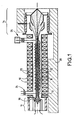
- Figure 1 recalls the general principle of a TOP.
- the TOP depicted is a propeller TOP, but other types of TOP such as TOP with coupled cavities, TOP with guides folded in meanders, etc., are equally concerned with the invention.
- TOPs have an elongated tubular sheath 10 in which vacuum is created, with at one end an electron gun 11 emitting an electron beam 12 and, at a second end, a collector 14; the collector collects the electrons that have given up part of their initial energy to the electromagnetic wave that we want to amplify.
- the electron beam 12 is substantially cylindrical over most of the length of the tube between the barrel 11 and the manifold 14 along an axis 15. This cylindrical beam shape is obtained on the one hand, thanks to the shape a cathode 16 of the electron gun 11 (convergent cathode in the form of bowl), and, on the other hand, by means of magnetic focusing provided over the entire length of the sheath 10 between the outlet of the barrel electron 11 and the collector input 14.
- cathode 16 which emits the electron beam 12.
- These means of focusing are permanent annular magnets 18 axially magnetized and alternating magnetization from one magnet to the next; these magnets surround the sheath 10 and are separated from each other by pole pieces 20 to high magnetic permeability.
- the electron beam 12 changes to inside a helical conductive structure 22 along which flows the microwave electromagnetic wave to be amplified; amplification of microwave energy occurs by interaction between this wave and the electron beam 12 passing through the center thereof.
- the propeller is used to slow down the microwave, so that its speed, along axis 15 of the electron beam 12, ie substantially equal to that of the beam of electrons 12.
- a signal to be amplified with power Pe is injected at one end of the helical conductive structure 22 through a plug and a window 24 inside the sheath 10.
- An amplified power signal Ps is extracted at another end of the helical conductive structure 22 at through a plug and a window 26.
- Figures 2 and 3 show in more detail how the scabbard 10 is thus realized connecting the sheath 10 with a casing 28 enclosing the whole sleeve 10.
- the sheath 10 proper is formed of the pole pieces 20 and spacers 30 separating the pole pieces 20.
- the spacers 30 are, for example, made from an alloy based on copper and nickel nonmagnetic.
- the outside diameter of the spacers 30 is smaller than that of the pole pieces 20, thus, the magnets 18 whose internal diameter is substantially equal to the outside diameter of the spacers 30 are held between the spacers, for example by means of resin.
- the thickness of the spacers 30 measured along the axis 15 is substantially equal to the thickness of the magnets 18.
- the propeller 22 is located inside the sheath 10 and dielectric rods 32 make it possible to support mechanically the propeller inside the sleeve 10.
- the rods 32 are elongated along axis 15 and are, for example, three in number arranged at 120 ° around the axis 15. This 120 ° arrangement of the sticks 32 is good visible in figure 3.
- Fins 34 mechanically hold the sleeve 10 to inside the casing 28.
- the fins 34 also make it possible to evacuate towards the casing 28 of the heat produced inside the sheath.
- the fins 34 are made from metal sheets, for example copper alloy.
- the fins 34 are arranged perpendicular to the axis 15 and they are based on the one hand, at the end of the pole pieces 20 and, on the other hand, on the casing 28.
- the production and assembly of the fins 34 are complicated to achieve. In particular, we are required to impose tight tolerances in dimensions of the pole pieces 20 and the fins 34 in order to ensure good mechanical and thermal contact between the pole pieces 20, the fins 34 and the casing 28.
- the invention aims to simplify the mechanical maintenance of the sheath 10 relative to the casing 28 while ensuring good transfer thermal between the sleeve 10 and the casing 28.
- the invention relates to an electronic tube comprising an elongated tubular sheath inside which develops a electron beam, a housing ensuring the mechanical maintenance of the sheath, and means for ensuring a thermal transfer from the sleeve to the casing in order to cool the sheath, characterized in that the means for ensuring the heat transfer include a resin filling a free volume located between the sleeve and the housing.
- the resin increases the rigidity of the mounted electronic tube in its housing 28.
- the removal of the fins improves the heat dissipation of the sheath 10 towards the casing 28. More specifically, the fins formed localized thermal bridges through which heat circulated. Replacing the fins by resin, the heat transfer is no longer localized, it is more homogeneous. This avoids possible hot spots between the fins 34.
- the fins 34 have been replaced by a resin 36 filling the free volume between the sheath 10 and the casing 28.
- This resin once polymerized, ensures that the times the mechanical retention of the sheath 10 relative to the casing 28 as well as the thermal transfer of the heat emitted inside the electronic tube towards the casing 28.
- a radiator fixed to the casing 28 or similar means, not shown in Figure 4, will, for example, remove this heat by a heat transfer fluid circulating in the radiator.
- the resin can, for example, be formed by "Stycast 3050" supplied by Emerson and Cuming, resin to which an adequate catalyst is added.
- granules 38 made are drowned in the resin. in a material whose thermal resistance is lower than that of resin. These granules improve the heat transfer of the sheath 10 towards the casing 28.
- metal granules by aluminum-based example.
- the dimensions of the granules 38 are chosen so that a characteristic dimension of these granules 38, by example the diameter, if the granules 38 are substantially spherical, is substantially equal or similar while remaining less than the smallest of dimensions of the free volume left between the sheath 10 and the casing 28.
- This characteristic is visible on figure 4 on which one distinguishes granules which can slide between the lower part of the sheath 10 and the casing 28. In this zone, the larger the granules 38, the better the heat transfer between the sleeve 10 and the casing 28.
- the number is reduced of contact zones between the sleeve 10 and the casing 28 passing through the granules. It is through these contact zones that the heat. The fewer these areas, the better the transfer thermal.
- the thermal conductivity is closer to that of the resin as the material constituting the powder or the granules. Thanks to this largest possible characteristic dimension of the granules 38, we is not obliged to choose a resin among that having a good conductivity thermal. This characteristic frees the choice of resin.
Landscapes
- Microwave Tubes (AREA)
- Amplifiers (AREA)
- Microwave Amplifiers (AREA)
- Cooling Or The Like Of Semiconductors Or Solid State Devices (AREA)
Abstract
Description
- maintenir l'étanchéité entre le vide régnant à l'intérieur du fourreau 10 et l'atmosphère extérieure ;
- maintenir et aligner de l'hélice 22 par l'intermédiaire des bâtonnets diélectriques 32 ;
- évacuer la chaleur produite dans le tube électronique vers l'extérieur.
- l'hélice 22 qui chauffe à la fois sous l'effet du bombardement de certains électrons mal focalisés et par effet joule, en raison des courants hyperfréquences qu'elle transporte ;
- du collecteur 14 qui est relié mécaniquement et donc thermiquement au fourreau 10 ;
- du canon à électrons 11 et plus particulièrement d'une cathode et de son filament de chauffage.
- la figure 1 représente schématiquement le fonctionnement général d'un tube électronique ;
- la figure 2 représente, en coupe par un plan contenant l'axe du faisceau d'électrons, un tube électronique connu ;
- la figure 3 représente en coupe par un plan perpendiculaire à l'axe du faisceau d'électrons, un tube électronique connu ;
- - la figure 4 représente en coupe par un plan perpendiculaire à l'axe du faisceau d'électrons, un tube électronique selon l'invention ;
Claims (2)
- Tube électronique comportant un fourreau tubulaire allongé (10) à l'intérieur duquel se développe un faisceau d'électrons (12), un carter (28) assurant le maintien mécanique du fourreau (10), et des moyens pour assurer un transfert thermique du fourreau (10) vers le carter (28) afin de refroidir le fourreau (10), caractérisé en ce que les moyens pour assurer le transfert thermique comportent une résine (36) remplissant un volume libre situé entre le fourreau (10) et le carter (28), en ce que les moyens pour assurer le transfert thermique comportent, noyés dans la résine, des granules (38) réalisés dans un matériau dont la résistance thermique est inférieure à celle de la résine et en ce qu'une dimension caractéristique des granules (38) est sensiblement égale tout en restant inférieure à la plus petite des dimensions du volume libre.
- Tube électronique selon la revendication 1, caractérisé en ce que le matériau des granules (38) comporte de l'aluminium.
Applications Claiming Priority (2)
| Application Number | Priority Date | Filing Date | Title |
|---|---|---|---|
| FR0116243A FR2833749B1 (fr) | 2001-12-14 | 2001-12-14 | Refroidissement d'un tube electronique |
| FR0116243 | 2001-12-14 |
Publications (2)
| Publication Number | Publication Date |
|---|---|
| EP1328004A2 true EP1328004A2 (fr) | 2003-07-16 |
| EP1328004A3 EP1328004A3 (fr) | 2003-07-23 |
Family
ID=8870533
Family Applications (1)
| Application Number | Title | Priority Date | Filing Date |
|---|---|---|---|
| EP02102726A Withdrawn EP1328004A3 (fr) | 2001-12-14 | 2002-12-11 | Tube électronique à fourreau tubulaire refroidi |
Country Status (3)
| Country | Link |
|---|---|
| US (1) | US6858973B2 (fr) |
| EP (1) | EP1328004A3 (fr) |
| FR (1) | FR2833749B1 (fr) |
Families Citing this family (3)
| Publication number | Priority date | Publication date | Assignee | Title |
|---|---|---|---|---|
| US8518304B1 (en) | 2003-03-31 | 2013-08-27 | The Research Foundation Of State University Of New York | Nano-structure enhancements for anisotropic conductive material and thermal interposers |
| FR2857331B1 (fr) * | 2003-07-11 | 2005-12-02 | Cit Alcatel | Dispositif de dissipation de chaleur a double conduction, pour un engin spatial |
| FR2958448A1 (fr) * | 2010-03-30 | 2011-10-07 | Astrium Sas | Dispositif de controle thermique d'un tube a collecteur rayonnant comportant un ecran, une boucle fluide et un radiateur a haute temperature |
Family Cites Families (13)
| Publication number | Priority date | Publication date | Assignee | Title |
|---|---|---|---|---|
| DE2213185A1 (de) * | 1972-03-17 | 1973-09-27 | Siemens Ag | Justierbare laufzeitroehre |
| JPS5474668A (en) * | 1977-11-28 | 1979-06-14 | Nec Corp | Traveliing-wave tube unit |
| DE2812409A1 (de) * | 1978-03-22 | 1979-09-27 | Licentia Gmbh | Elektronenstrahlroehre |
| DE3433718A1 (de) * | 1984-09-14 | 1986-03-27 | Licentia Patent-Verwaltungs-Gmbh, 6000 Frankfurt | Lauffeldroehre |
| US4740657A (en) * | 1986-02-14 | 1988-04-26 | Hitachi, Chemical Company, Ltd | Anisotropic-electroconductive adhesive composition, method for connecting circuits using the same, and connected circuit structure thus obtained |
| FR2634054B1 (fr) | 1988-07-05 | 1996-02-09 | Thomson Csf | Cathode pour emission d'electrons et tube electronique comprenant une telle cathode |
| FR2637731A1 (fr) | 1988-10-11 | 1990-04-13 | Thomson Csf | Tube a onde progressive muni d'un dispositif de couplage etanche entre sa ligne a retard et un circuit hyperfrequence externe |
| FR2638891A1 (fr) | 1988-11-04 | 1990-05-11 | Thomson Csf | Fenetre etanche pour tube electronique hyperfrequence et tube a ondes progressives comportant cette fenetre |
| FR2647953B1 (fr) | 1989-05-30 | 1991-08-16 | Thomson Tubes Electroniques | Mode de construction d'une ligne a retard a helice et tubes a ondes progressives utilisant ce mode de construction |
| FR2650702B1 (fr) | 1989-08-01 | 1996-07-05 | Thomson Tubes Electroniques | Tube hyperfrequence muni au moins d'une piece axiale emmanchee a froid dans une enveloppe coaxiale |
| US5288769A (en) * | 1991-03-27 | 1994-02-22 | Motorola, Inc. | Thermally conducting adhesive containing aluminum nitride |
| US5834337A (en) * | 1996-03-21 | 1998-11-10 | Bryte Technologies, Inc. | Integrated circuit heat transfer element and method |
| KR20000064867A (ko) * | 1997-02-07 | 2000-11-06 | 아이. 데이비드 크로산 | 전도성,수지-기재 조성물 |
-
2001
- 2001-12-14 FR FR0116243A patent/FR2833749B1/fr not_active Expired - Fee Related
-
2002
- 2002-12-11 EP EP02102726A patent/EP1328004A3/fr not_active Withdrawn
- 2002-12-13 US US10/318,362 patent/US6858973B2/en not_active Expired - Fee Related
Also Published As
| Publication number | Publication date |
|---|---|
| US20040004423A1 (en) | 2004-01-08 |
| EP1328004A3 (fr) | 2003-07-23 |
| US6858973B2 (en) | 2005-02-22 |
| FR2833749B1 (fr) | 2004-04-02 |
| FR2833749A1 (fr) | 2003-06-20 |
Similar Documents
| Publication | Publication Date | Title |
|---|---|---|
| WO2004114353A1 (fr) | Tube generateur de rayons x a ensemble porte-cible orientable | |
| FR2833749A1 (fr) | Refroidissement d'un tube electronique | |
| FR2479558A1 (fr) | Tube a ondes progressives a cavites couplees et focalisation par aimants permanents alternes, et ensemble amplificateur comprenant un tel tube | |
| FR2578357A1 (fr) | Gyrotron | |
| FR2631486A1 (fr) | Lampe a decharge de haute intensite sabs electrodes | |
| FR2691012A1 (fr) | Canon de pierce à électrode d'échelonnement. | |
| EP0376827A1 (fr) | Tube à faisceau d'électrons refroidi partiellement par rayonnement direct | |
| EP0401065B1 (fr) | Mode de construction d'une ligne à retard à hélice | |
| FR2703508A1 (fr) | Système de focalisation à aimants permanents périodiques pour faisceau d'électrons. | |
| FR2496337A1 (fr) | Structure d'aimants permanents pour tubes electroniques a faisceau lineaire | |
| FR2833748A1 (fr) | Tube electronique a collecteur simplifie | |
| FR2606937A1 (fr) | Ligne a retard a couplage par cavites pour tube a onde progressive | |
| FR2790595A1 (fr) | Circuit de ligne a retard en helice | |
| EP0364335A1 (fr) | Tube à onde progressive muni d'un dispositif de couplage étanche entre sa ligne à retard et circuit hyperfréquence externe | |
| EP1251544B1 (fr) | Tube électronique amplificateur hyperfréquence avec fiche d'entrée miniature et procédé de fabrication | |
| FR2737042A1 (fr) | Collecteur d'electrons multietage supportant des tensions elevees et tube electronique muni d'un tel collecteur | |
| EP0454540A1 (fr) | Convertisseur de mode de propagation guidée des ondes électromagnétiques, et tube électronique comportant un tel convertisseur | |
| FR2790594A1 (fr) | Canon a electrons possedant une cathode froide a emission de champ et tube micro-ondes utilisant ce canon a electrons | |
| FR2765727A1 (fr) | Radiateur thermique utilise pour refroidir un tube a onde progressive par un rayonnement thermique | |
| FR2485801A1 (fr) | Dispositif de couplage entre la ligne a retard d'un tube a onde progressive et le circuit externe de transmission de l'energie du tube, et tube a onde progressive comportant un tel dispositif | |
| FR2683091A1 (fr) | Dispositif de refroidissement ameliore pour tube hyperfrequence. | |
| EP0350360B1 (fr) | Magnétron agile avec moteur d'accord à refroidissement amélioré | |
| FR2669771A1 (fr) | Cathode amelioree pour tubes hyperfrequence. | |
| FR2683941A1 (fr) | Collecteur de faisceau d'electrons. | |
| EP4456127A1 (fr) | Combineur coaxial cylindrique |
Legal Events
| Date | Code | Title | Description |
|---|---|---|---|
| PUAI | Public reference made under article 153(3) epc to a published international application that has entered the european phase |
Free format text: ORIGINAL CODE: 0009012 |
|
| PUAL | Search report despatched |
Free format text: ORIGINAL CODE: 0009013 |
|
| AK | Designated contracting states |
Designated state(s): AT BE BG CH CY CZ DE DK EE ES FI FR GB GR IE IT LI LU MC NL PT SE SI SK TR |
|
| AX | Request for extension of the european patent |
Extension state: AL LT LV MK RO |
|
| AK | Designated contracting states |
Designated state(s): AT BE BG CH CY CZ DE DK EE ES FI FR GB GR IE IT LI LU MC NL PT SE SI SK TR |
|
| AX | Request for extension of the european patent |
Extension state: AL LT LV MK RO |
|
| 17P | Request for examination filed |
Effective date: 20031206 |
|
| AKX | Designation fees paid |
Designated state(s): AT BE BG CH CY CZ DE DK EE ES FI FR GB GR IE IT LI LU MC NL PT SE SI SK TR |
|
| STAA | Information on the status of an ep patent application or granted ep patent |
Free format text: STATUS: THE APPLICATION IS DEEMED TO BE WITHDRAWN |
|
| 18D | Application deemed to be withdrawn |
Effective date: 20060701 |