EP1327882B1 - Leakage magnetism detecting sensor of magnetic penetration apparatus - Google Patents
Leakage magnetism detecting sensor of magnetic penetration apparatus Download PDFInfo
- Publication number
- EP1327882B1 EP1327882B1 EP01976745A EP01976745A EP1327882B1 EP 1327882 B1 EP1327882 B1 EP 1327882B1 EP 01976745 A EP01976745 A EP 01976745A EP 01976745 A EP01976745 A EP 01976745A EP 1327882 B1 EP1327882 B1 EP 1327882B1
- Authority
- EP
- European Patent Office
- Prior art keywords
- magnetism
- magnetism sensing
- soft
- magnetic material
- sensor
- Prior art date
- Legal status (The legal status is an assumption and is not a legal conclusion. Google has not performed a legal analysis and makes no representation as to the accuracy of the status listed.)
- Expired - Lifetime
Links
Images


Classifications
-
- G—PHYSICS
- G01—MEASURING; TESTING
- G01N—INVESTIGATING OR ANALYSING MATERIALS BY DETERMINING THEIR CHEMICAL OR PHYSICAL PROPERTIES
- G01N27/00—Investigating or analysing materials by the use of electric, electrochemical, or magnetic means
- G01N27/72—Investigating or analysing materials by the use of electric, electrochemical, or magnetic means by investigating magnetic variables
- G01N27/82—Investigating or analysing materials by the use of electric, electrochemical, or magnetic means by investigating magnetic variables for investigating the presence of flaws
Definitions
- This invention relates to leak magnetism detection sensors for use in magnetic flaw detection systems, and particularly, it relates to a leak magnetism detection sensor for the online magnetic flaw detection system that is suitable for use in leakage flux sensing for detecting surface flaws and inclusions of a steel strip by sensing the leakage flux arising from the internal and surface of the ferromagnetic object under test.
- the flaw detection technique using leakage flux is a method for detecting defect by generating a magnetic field along the traveling direction of the target object and then sensing the leakage flux arising from internal and surface defects of the object.
- sensors for detecting leakage flux there are semiconductor-type magnetic sensors such as magnetic diodes, magneto-resistance devices and Hall devices, and the coil-type ones such as planar coils and induction coil sensors that hold coils wound on ferrite.
- the magnetic diode has the advantages of being high in sensitivity and small in size. On the other hand, it has the disadvantages of having poor temperature characteristics, large inherit noise and low mechanical strength.
- the coil-type sensors have simple structures and good temperature characteristics, while they have a disadvantage of being low in sensitivity.
- the Hall device which was a low-sensitivity semiconductor magnetic sensor, has come to have improved sensitivity and temperature characteristics, thus being widely adopted as a leak magnetism detection sensor for use in the flaw detection using leakage flux.
- Tin plates which are employed in food cans, are strongly worked during the production of two-piece cans (DI cans).
- inclusions non-metallic inclusions inside the material (hereafter, simply referred to as inclusions) cause cracks during working.
- the target for sensing is a volume of 0.5x10 -3 mm 3 , assuming an elliptic region of, approximately, 1.0mm long, 0.1mm wide and 0.01mm thick.
- Japanese Patent Laid-Open Publication No. Hei. 4-296648 has also disclosed a ferromagnetic jig installed near a magnetic sensor.
- This jig is a magnetic shield prepared for reducing magnetic flux around the magnetic sensor so that the high density of magnetic flux in the surrounding space bypasses the magnetic sensor and thereby the magnetic sensor may not saturate.
- This jig is expected to improve sensor sensitivity to some extent but does not aim to expand the detection coverage.
- This invention has been made to solve those conventional problems and aims to reduce the number of sensors and signal processing circuits by expanding the detection coverage of each leak magnetism detection sensor.
- the invention provides a leak magnetism detection sensor and a method of detecting flaws as described in the appended independent and dependent claims.
- FIG. 1 shows the leak magnetism detection sensor of the present invention (for example, a semiconductor sensor).
- a soft-magnetic material 14 that has a permeability much higher than that of air and is larger than a magnetism sensing face 12A of a magnetism sensing device (for example, a Hall device) of a semiconductor magnetic sensor 12 is installed on the opposite side of this magnetism sensing face 12A, namely, on the other side of the sensor facing the target strip, apart from this magnetism sensing face 12A at a predetermined distance, namely apart from the magnetism sensing device.
- the soft-magnetic material 14 attracts leakage flux F arising from an inclusion 10A in a steel strip 10.
- the coverage of each sensor becomes larger and its sensitivity is enhanced because more of the magnetic flux F is concentrated to intersect the magnetism sensing face 12A in the direction perpendicular to both magnetism sensing face 12A and strip 10.
- the semiconductor magnetic sensor 12 shown in FIG. 1 may have a magnetism sensing device 12C such as a Hall device on the surface of a soft-magnetic material 12B such as ferrite. Namely, the soft-magnetic material 12B is kept contact with the opposite side of the magnetism sensing face of the magnetism sensing device 12C. Seen from the target strip 10, the semiconductor magnetic sensor 12 holding the magnetism sensing device 12C on the side facing the strip 10 and the soft-magnetic material 14 are installed in this order. Then since further more of the leakage flux F is concentrated to intersect the magnetism sensing face 12A at right angles as shown in FIG. 3 , the detection coverage of each sensor is expanded and its sensitivity is enhanced in this further preferable example.
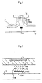
- Reference numeral 16 in FIG. 2 denotes a supporting plate for sensor mounting.
- the semiconductor sensor may have the magnetism sensing device 12C such as a Hall device on the surface of the soft-magnetic material 12B such as ferrite and may sandwich this magnetism sensing device 12C such as a Hall device between soft-magnetic materials 12B and 12D such as ferrite by installing a soft-magnetic material 12D like ferrite adhered to the magnetism sensing face 12A of the magnetism sensing device like a Hall device.
- the magnetism sensing face is protected and the sensitivity is further raised since the leakage flux F intersects the magnetism sensing face 12A in the direction normal thereto.
- the Hall device has a low noise level, it can easily detect such small inclusions that are referred to in this invention.
- a small Hall device can be made very thin, it enables to downsize the leak magnetism detection sensor of the configuration in accordance with this invention particularly in the direction perpendicular to the surface of the strip. As a result, the Hall device makes it easier to shorten the distance between the magnetism sensing face and the target strip during measurement and to raise sensing accuracy, compared with other magnetism sensing devices.
- leakage flux F presents a distribution shown in FIG. 5 in the conventional configuration having a sensor element alone.
- Leakage flux F crosses the magnetism sensing face 12A of the sensor 12 at shallow angles. Then since the portion of magnetic flux normal to the magnetism sensing face 12A is small, the detection coverage per sensor is small.
- FIG. 6 is a schematic view illustrating the whole configuration of the embodiment of the present invention
- FIG. 7 is its plan view
- FIG. 8 is a sectional view illustrating the geometries of the semiconductor magnetic sensor (Hall device in this example) and the soft-magnetic material that constitute the leak magnetism detection sensor in accordance with the present invention.
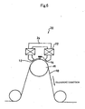
- the semiconductor magnetic sensor 12, soft-magnetic material 14 and magnetizing yoke 24 where magnetizing coils 22 are wound for magnetizing the strip 10 according to the present invention are integrated into a magnetic sensor head 20 and installed in the vicinity of a non-magnetic roll 11 that conveys the strip 10 in the direction shown by the arrow.
- the magnetizing yoke 24 magnetizes the strip 10. Then if the strip 10 has inclusions and/or surface flaws, leakage flux appears. This leakage flux is collected by the soft-magnetic material 14 that is larger than the magnetism sensing face 12A of the semiconductor magnetic sensor 12 and concentrated to intersect the magnetism sensing face 12A of the semiconductor magnetic sensor 12. Then the detection coverage of each sensor can be enlarged.
- FIG. 7 is a schematic diagram illustrating the geometries of the semiconductor magnetic sensor 12 and the soft-magnetic material 14 mounted on the opposite side of the magnetism sensing face 12A.
- the leak magnetism detection sensor according to the present invention includes the semiconductor magnetic sensor 12 and the soft-magnetic material 14 that is buried in the supporting plate 16 for mounting and has a width, W, which is larger than that of the magnetism sensing face 12A.
- this embodiment uses a magnetic sensor of the integrated structure, a horizontal magnetic field is created between the poles of the yoke 24 even when the strip under test is standing still. Because this floating magnetic field exerts a negative effect on magnetic materials, this embodiment employs a soft-magnetic material that has strong magnetized characteristics and allows a high flux density.
- the soft-magnetic material 14 may be, approximately, 1-10mm in width W and 0.05-3mm in thickness T; and it may be installed at a distance, D, of 0.1-3mm from the opposite side of the magnetism sensing face 12A of the semiconductor magnetic sensor 12. As shown in FIG. 7 , the soft-magnetic material may be as wide as the full width of the employed sensor.
- the soft-magnetic material 14 may preferably be located in the center of the width of the projection of the magnetism sensing face 12A onto the soft-magnetic material 14.
- the soft-magnetic material 14 is buried in the supporting plate 16 prepared for sensor mounting.
- the location of the soft-magnetic material is not limited to the above example.
- the soft-magnetic material 14 may be other than ferrite, for example, inexpensive materials such as cold rolled steel sheet (annealed steel sheet).
- the whole structure is simple in this embodiment because the semiconductor magnetic sensor 12 and soft-magnetic material 14 are integrated into the magnetic sensor head 20 together with the magnetizing coils 22 and magnetizing yoke 24. It is, however, possible to separate the magnetizing coils 22 and magnetizing yoke 24 from the semiconductor magnetic sensor 12 and soft-magnetic material 14.
- the employed soft-magnetic material 14 was a cold rolled steel plate that was larger than the magnetism sensing face of the magnetism sensing device, namely, 10 times each of the lengths in the longer and shorter axis directions of the magnetism sensing face.
- the target object for measurement was a 0.23mm-thick tin plate made from continuous casting material, having an inclusion that was 1.0mm long, 0.1mm wide and approximately 0.01mm thick.
- the rotation speed of the roll was set at 200mpm and the liftoff between the magnetic sensor and the target object was set at 1.0mm.
- the magnetic sensor head 20 was moved rightward at 0.2mm pitches from the position corresponding to the left end of the lateral axis of FIG. 9 to measure the inclusion that repeatedly passed the same position.
- the measurements were carried out with the soft-magnetic material 14 (solid line A) and without such a soft-magnetic material like the case of a conventional sensor (broken line B). Then as shown in FIG.
- the width at half the peak value (half width) changed according to the presence/absence of the soft-magnetic material 14.
- the half width (7.8) for the case having the soft-magnetic material 14 was about 20% larger than that (6.5) for the case having no soft-magnetic material. Thus, it would be possible to reduce the number of sensors and signal processing circuits about 20%.
- the sensor output of magnetism sensing devices grows proportionally as the magnetizing current rises, and the sensor output tends to saturate after the magnetizing current has reached a certain level.
- the semiconductor sensor when the semiconductor sensor employs a Hall device mounted on ferrite, the sensor output saturates at a lower magnetizing current, compared with the case using a Hall device alone. Then, the sensor output tends to become smaller as the magnetizing current is increased.
- the sensor output does not saturate until the magnetizing current has reached a higher value and thus it is confirmed that the sensor output at saturation becomes larger, compared with the case of having no soft-magnetic material 14. If the sensor output does not saturate until the magnetizing current has reached a large value, it is possible to run a large magnetizing current during measurement. In other words, it is confirmed that the sensor is able to measure target objects that are rather thick.
- the sensor output itself becomes large and thereby it is confirmed that the measurement accuracy can be improved.
- the leak magnetism detection sensor is preferably a semiconductor magnetic sensor using the Hall device.
- the leak magnetism detection sensor may be other than this type.
- this invention expands the detection coverage per leak magnetism detection sensor, the number of sensors and signal processing circuits can be reduced. Moreover, since the sensor sensitivity is enhanced, it is possible to detect micro inclusions even if the liftoff is set at a large value, for example, 1mm.
Description
- This invention relates to leak magnetism detection sensors for use in magnetic flaw detection systems, and particularly, it relates to a leak magnetism detection sensor for the online magnetic flaw detection system that is suitable for use in leakage flux sensing for detecting surface flaws and inclusions of a steel strip by sensing the leakage flux arising from the internal and surface of the ferromagnetic object under test.
- The flaw detection technique using leakage flux is a method for detecting defect by generating a magnetic field along the traveling direction of the target object and then sensing the leakage flux arising from internal and surface defects of the object. As sensors for detecting leakage flux, there are semiconductor-type magnetic sensors such as magnetic diodes, magneto-resistance devices and Hall devices, and the coil-type ones such as planar coils and induction coil sensors that hold coils wound on ferrite.
- Among them, the magnetic diode has the advantages of being high in sensitivity and small in size. On the other hand, it has the disadvantages of having poor temperature characteristics, large inherit noise and low mechanical strength.
- The coil-type sensors have simple structures and good temperature characteristics, while they have a disadvantage of being low in sensitivity.
- Meanwhile, the Hall device, which was a low-sensitivity semiconductor magnetic sensor, has come to have improved sensitivity and temperature characteristics, thus being widely adopted as a leak magnetism detection sensor for use in the flaw detection using leakage flux.
- Tin plates, which are employed in food cans, are strongly worked during the production of two-piece cans (DI cans). Thus non-metallic inclusions inside the material (hereafter, simply referred to as inclusions) cause cracks during working. The target for sensing is a volume of 0.5x10⁻³mm3, assuming an elliptic region of, approximately, 1.0mm long, 0.1mm wide and 0.01mm thick. Thus there are such problems that as many as around 1000 semiconductor magnetic sensors are needed to perform an online flaw detection over the full width of the target and that a huge number of signal processing circuits for as many as 1000 channels must be prepared.
- An invention similar to this invention is disclosed in Japanese Utility Model Laid-Open Publication No.
Hei. 7-38956 claims - Japanese Patent Laid-Open Publication No.
Hei. 4-296648 - This invention has been made to solve those conventional problems and aims to reduce the number of sensors and signal processing circuits by expanding the detection coverage of each leak magnetism detection sensor.
- In order to solve the problems mentioned above, the invention provides a leak magnetism detection sensor and a method of detecting flaws as described in the appended independent and dependent claims.
-
FIG. 1 shows the leak magnetism detection sensor of the present invention (for example, a semiconductor sensor). In this leak magnetism detection sensor, a soft-magnetic material 14 that has a permeability much higher than that of air and is larger than a magnetism sensingface 12A of a magnetism sensing device (for example, a Hall device) of a semiconductormagnetic sensor 12 is installed on the opposite side of this magnetism sensingface 12A, namely, on the other side of the sensor facing the target strip, apart from this magnetism sensingface 12A at a predetermined distance, namely apart from the magnetism sensing device. Then the soft-magnetic material 14 attracts leakage flux F arising from aninclusion 10A in asteel strip 10. As a result, the coverage of each sensor becomes larger and its sensitivity is enhanced because more of the magnetic flux F is concentrated to intersect the magnetism sensingface 12A in the direction perpendicular to both magnetism sensingface 12A andstrip 10. - As shown in
FIG. 2 , the semiconductormagnetic sensor 12 shown inFIG. 1 may have amagnetism sensing device 12C such as a Hall device on the surface of a soft-magnetic material 12B such as ferrite. Namely, the soft-magnetic material 12B is kept contact with the opposite side of the magnetism sensing face of themagnetism sensing device 12C. Seen from thetarget strip 10, the semiconductormagnetic sensor 12 holding themagnetism sensing device 12C on the side facing thestrip 10 and the soft-magnetic material 14 are installed in this order. Then since further more of the leakage flux F is concentrated to intersect the magnetism sensingface 12A at right angles as shown inFIG. 3 , the detection coverage of each sensor is expanded and its sensitivity is enhanced in this further preferable example.Reference numeral 16 inFIG. 2 denotes a supporting plate for sensor mounting. - Higher sensitivity is provided by the following mechanism. When the
magnetism sensing device 12C such as a Hall device is mounted on the soft-magnetic material 12B such as ferrite as shown inFIG. 2 , more of the leakage flux F gathered by the aforementioned soft-magnetic material 14 is further gathered in the magnetism sensingface 12A by the soft-magnetic material 12B used in the semiconductormagnetic sensor 12. As a result, more of the leak flux F comes to intersect the magnetism sensingface 12A in the direction normal thereto. - As shown in
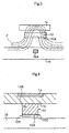
FIG. 4 , the semiconductor sensor may have themagnetism sensing device 12C such as a Hall device on the surface of the soft-magnetic material 12B such as ferrite and may sandwich thismagnetism sensing device 12C such as a Hall device between soft-magnetic materials 12B and 12D such as ferrite by installing a soft-magnetic material 12D like ferrite adhered to the magnetism sensingface 12A of the magnetism sensing device like a Hall device. As a result, the magnetism sensing face is protected and the sensitivity is further raised since the leakage flux F intersects the magnetism sensingface 12A in the direction normal thereto. - It is preferable to employ a Hall device as the
magnetism sensing device 12C. Since the Hall device has a low noise level, it can easily detect such small inclusions that are referred to in this invention. In addition, since a small Hall device can be made very thin, it enables to downsize the leak magnetism detection sensor of the configuration in accordance with this invention particularly in the direction perpendicular to the surface of the strip. As a result, the Hall device makes it easier to shorten the distance between the magnetism sensing face and the target strip during measurement and to raise sensing accuracy, compared with other magnetism sensing devices. - In contrast, the leakage flux presents a distribution shown in
FIG. 5 in the conventional configuration having a sensor element alone. Leakage flux F crosses the magnetism sensingface 12A of thesensor 12 at shallow angles. Then since the portion of magnetic flux normal to the magnetism sensingface 12A is small, the detection coverage per sensor is small. -
-
FIG. 1 is a sectional view illustrating the principle of the present invention; -
FIG. 2 is a sectional view illustrating the structure of the semiconductor magnetic sensor in accordance with an improved example of the invention; -
FIG. 3 is a sectional view illustrating the principle of the improved example; -
FIG. 4 is a sectional view illustrating the structure of the semiconductor magnetic sensor in accordance with another improved example of the invention; -
FIG. 5 is a sectional view illustrating the conventional principle; -
FIG. 6 is a sectional view illustrating the whole configuration of an embodiment of the present invention; -
FIG. 7 is its plan view; -
FIG. 8 is a sectional view illustrating the structure of the semiconductor magnetic sensor; and -
FIG. 9 is a graph illustrating the results of a test that was conducted to confirm the effect of the invention. - Now an embodiment of the present invention is described in detail with reference to the accompanying drawings.
-
FIG. 6 is a schematic view illustrating the whole configuration of the embodiment of the present invention;FIG. 7 is its plan view; andFIG. 8 is a sectional view illustrating the geometries of the semiconductor magnetic sensor (Hall device in this example) and the soft-magnetic material that constitute the leak magnetism detection sensor in accordance with the present invention. - Referring now to
FIG. 6 , the semiconductormagnetic sensor 12, soft-magnetic material 14 andmagnetizing yoke 24 wheremagnetizing coils 22 are wound for magnetizing thestrip 10 according to the present invention are integrated into amagnetic sensor head 20 and installed in the vicinity of anon-magnetic roll 11 that conveys thestrip 10 in the direction shown by the arrow. - When a DC current runs in the
magnetizing coil 22, themagnetizing yoke 24 magnetizes thestrip 10. Then if thestrip 10 has inclusions and/or surface flaws, leakage flux appears. This leakage flux is collected by the soft-magnetic material 14 that is larger than the magnetism sensingface 12A of the semiconductormagnetic sensor 12 and concentrated to intersect the magnetism sensingface 12A of the semiconductormagnetic sensor 12. Then the detection coverage of each sensor can be enlarged. -
FIG. 7 is a schematic diagram illustrating the geometries of the semiconductormagnetic sensor 12 and the soft-magnetic material 14 mounted on the opposite side of the magnetism sensingface 12A. The leak magnetism detection sensor according to the present invention includes the semiconductormagnetic sensor 12 and the soft-magnetic material 14 that is buried in the supportingplate 16 for mounting and has a width, W, which is larger than that of the magnetism sensingface 12A. - In case of the present embodiment using a magnetic sensor of the integrated structure, a horizontal magnetic field is created between the poles of the
yoke 24 even when the strip under test is standing still. Because this floating magnetic field exerts a negative effect on magnetic materials, this embodiment employs a soft-magnetic material that has strong magnetized characteristics and allows a high flux density. - The preferable geometry and the mounting position of the soft-
magnetic material 14 change with the size of defects in the target object. For example, the soft-magnetic material may be, approximately, 1-10mm in width W and 0.05-3mm in thickness T; and it may be installed at a distance, D, of 0.1-3mm from the opposite side of themagnetism sensing face 12A of the semiconductormagnetic sensor 12. As shown inFIG. 7 , the soft-magnetic material may be as wide as the full width of the employed sensor. - As mentioned before, it is necessary to make the soft-
magnetic material 14 larger than themagnetism sensing face 12A, preferably as much as 5-30 times each of lengths in longer and shorter axis directions of the magnetism sensing face. At the same time, the soft-magnetic material 14 may preferably be located in the center of the width of the projection of themagnetism sensing face 12A onto the soft-magnetic material 14. - In this embodiment, it is easy to make the sensor structure simple because the soft-
magnetic material 14 is buried in the supportingplate 16 prepared for sensor mounting. The location of the soft-magnetic material, however, is not limited to the above example. The soft-magnetic material 14 may be other than ferrite, for example, inexpensive materials such as cold rolled steel sheet (annealed steel sheet). - Besides, the whole structure is simple in this embodiment because the semiconductor
magnetic sensor 12 and soft-magnetic material 14 are integrated into themagnetic sensor head 20 together with the magnetizing coils 22 and magnetizingyoke 24. It is, however, possible to separate the magnetizing coils 22 and magnetizingyoke 24 from the semiconductormagnetic sensor 12 and soft-magnetic material 14. - Then the results of an experiment that was conducted to make sure the effect of the present invention are described below. The performance of the invention was confirmed in a test where the integrated
magnetic sensor head 20 of this embodiment was installed on an experimental roll that was able to repeat measurement of the same position. - In the test, a Hall device was employed as the magnetism sensing device and the semiconductor magnetic sensor employed this Hall device on the surface of ferrite. The employed soft-
magnetic material 14 was a cold rolled steel plate that was larger than the magnetism sensing face of the magnetism sensing device, namely, 10 times each of the lengths in the longer and shorter axis directions of the magnetism sensing face. - The target object for measurement was a 0.23mm-thick tin plate made from continuous casting material, having an inclusion that was 1.0mm long, 0.1mm wide and approximately 0.01mm thick. The rotation speed of the roll was set at 200mpm and the liftoff between the magnetic sensor and the target object was set at 1.0mm. The
magnetic sensor head 20 was moved rightward at 0.2mm pitches from the position corresponding to the left end of the lateral axis ofFIG. 9 to measure the inclusion that repeatedly passed the same position. The measurements were carried out with the soft-magnetic material 14 (solid line A) and without such a soft-magnetic material like the case of a conventional sensor (broken line B). Then as shown inFIG. 9 , the width at half the peak value (half width) changed according to the presence/absence of the soft-magnetic material 14. The half width (7.8) for the case having the soft-magnetic material 14 was about 20% larger than that (6.5) for the case having no soft-magnetic material. Thus, it would be possible to reduce the number of sensors and signal processing circuits about 20%. - Furthermore, the fluctuations in sensor output caused by changes in the magnetizing current or the current running in the magnetizing coil were studied according to the presence/absence of the soft-
magnetic material 14. - In general, the sensor output of magnetism sensing devices such as Hall devices grows proportionally as the magnetizing current rises, and the sensor output tends to saturate after the magnetizing current has reached a certain level.
- As is the case with the present embodiment, when the semiconductor sensor employs a Hall device mounted on ferrite, the sensor output saturates at a lower magnetizing current, compared with the case using a Hall device alone. Then, the sensor output tends to become smaller as the magnetizing current is increased.
- Meanwhile, when such a semiconductor sensor employs the soft-
magnetic material 14, the sensor output does not saturate until the magnetizing current has reached a higher value and thus it is confirmed that the sensor output at saturation becomes larger, compared with the case of having no soft-magnetic material 14. If the sensor output does not saturate until the magnetizing current has reached a large value, it is possible to run a large magnetizing current during measurement. In other words, it is confirmed that the sensor is able to measure target objects that are rather thick. - Besides, the sensor output itself becomes large and thereby it is confirmed that the measurement accuracy can be improved.
- At around the magnetizing current causing the saturation of sensor output, the changes in sensor output with respect to magnetizing current become smaller in the presence of the soft-
magnetic material 14 than those in its absence, and thus it is also confirmed that reliable measurements can be conducted. - In the above descriptions, the present invention was used in the online flaw detection for steel sheets. This invention, however, can be adopted in other applications. The leak magnetism detection sensor is preferably a semiconductor magnetic sensor using the Hall device. However, the leak magnetism detection sensor may be other than this type.
- Since this invention expands the detection coverage per leak magnetism detection sensor, the number of sensors and signal processing circuits can be reduced. Moreover, since the sensor sensitivity is enhanced, it is possible to detect micro inclusions even if the liftoff is set at a large value, for example, 1mm.
Claims (4)
- A leak magnetism detection sensor (20) for a magnetic flaw detection system that generates a magnetic field along a traveling direction of a target strip (10) and detects online leakage flux arising from internal and surface defects (10A) of the strip to provide signals indicating existence of defects, wherein a soft-magnetic material (14) is installed on an opposite side of a magnetism sensing face (12A) of the sensor; characterized in that:the sensor (20) comprises a flaw detection head equipped with a number of magnetism sensing devices (12C) arrayed across a width of the strip;the soft-magnetic material (14) is larger than said magnetism sensing face (12A) by several times each of lengths in longer and shorter axis directions of the magnetism sensing face, andeach of said magnetism sensing devices (12C) is located apart from said soft-magnetic material (14) and another soft-magnetic material (12B) is installed to be kept in contact with said opposite side of the magnetism sensing face (12A) of said magnetism sensing devices (12C).
- The leak magnetism detection sensor for a magnetic flaw detection system according to claim 1, characterized in that still another soft-magnetic material (12D) is installed to be kept in contact with the magnetism sensing face (12A) of said magnetism sensing device (12C).
- The leak magnetism detection sensor for a magnetic flaw detection system according to claim 1, characterized in that said magnetism sensing device is a Hall device.
- A method of detecting flaws (10A) online in strips (10), using a leak magnetism detection sensor (20) for detecting leakage flux arising from internal and surface defects thereof, which sensor comprises a soft-magnetic material (14) that is installed on an opposite side of a magnetism sensing face (12A); characterised by:providing said leak magnetism detection sensor (20) with a number of magnetism sensing devices (12C) arrayed across a width of a target strip;said soft-magnetic material (14) being larger than said magnetism sensing face (12A) by several times each of lengths in longer and shorter axis directions of the magnetism sensing face, andlocating each of said magnetism sensing devices (12C) apart from said soft-magnetic material (14) and installing another soft-magnetic material (12B) to be kept in contact with said opposite side of the magnetism sensing face (12A) of said magnetism sensing device (12C).
Applications Claiming Priority (5)
| Application Number | Priority Date | Filing Date | Title |
|---|---|---|---|
| JP2000317711 | 2000-10-18 | ||
| JP2000317711 | 2000-10-18 | ||
| JP2001299768A JP3811039B2 (en) | 2000-10-18 | 2001-09-28 | Magnetic leak detection sensor for magnetic flaw detector |
| JP2001299768 | 2001-09-28 | ||
| PCT/JP2001/009159 WO2002033398A1 (en) | 2000-10-18 | 2001-10-18 | Leakage magnetism detecting sensor of magnetic penetration apparatus |
Publications (3)
| Publication Number | Publication Date |
|---|---|
| EP1327882A1 EP1327882A1 (en) | 2003-07-16 |
| EP1327882A4 EP1327882A4 (en) | 2005-04-13 |
| EP1327882B1 true EP1327882B1 (en) | 2013-03-13 |
Family
ID=26602307
Family Applications (1)
| Application Number | Title | Priority Date | Filing Date |
|---|---|---|---|
| EP01976745A Expired - Lifetime EP1327882B1 (en) | 2000-10-18 | 2001-10-18 | Leakage magnetism detecting sensor of magnetic penetration apparatus |
Country Status (7)
| Country | Link |
|---|---|
| US (1) | US6774627B2 (en) |
| EP (1) | EP1327882B1 (en) |
| JP (1) | JP3811039B2 (en) |
| KR (1) | KR100671630B1 (en) |
| CN (1) | CN1225655C (en) |
| CA (1) | CA2396205C (en) |
| WO (1) | WO2002033398A1 (en) |
Families Citing this family (27)
| Publication number | Priority date | Publication date | Assignee | Title |
|---|---|---|---|---|
| JP3811039B2 (en) | 2000-10-18 | 2006-08-16 | Jfeスチール株式会社 | Magnetic leak detection sensor for magnetic flaw detector |
| US6911826B2 (en) * | 2001-06-12 | 2005-06-28 | General Electric Company | Pulsed eddy current sensor probes and inspection methods |
| US7007371B1 (en) * | 2003-09-24 | 2006-03-07 | Sauer-Danfoss Inc. | Method of manufacturing a magnetic strip magnet speed ring |
| DE102004035174B4 (en) * | 2004-07-16 | 2006-08-10 | V&M Deutschland Gmbh | Method and device for non-destructive testing of pipes |
| WO2006046578A1 (en) * | 2004-10-28 | 2006-05-04 | Toyo Kohan Co., Ltd. | Device and method for inspecting scratch on cell external case |
| CN100432665C (en) * | 2005-08-05 | 2008-11-12 | 营口市北方检测设备有限公司 | Online detecting device and method for two-field leakage magnetic flux of defects on steel products surface |
| JP4825525B2 (en) * | 2006-02-01 | 2011-11-30 | 株式会社日立ビルシステム | Wire rope flaw detector |
| CN100427947C (en) * | 2006-06-16 | 2008-10-22 | 清华大学 | Large-area steel plate defect flux-leakage detection method |
| JP4295774B2 (en) * | 2006-07-20 | 2009-07-15 | 株式会社日立ビルシステム | Wire rope flaw detector |
| US9170234B2 (en) * | 2006-11-01 | 2015-10-27 | Industry-Academic Cooperation Foundation, Chosun University | Magnetic sensor array and apparatus for detecting defect using the magnetic sensor array |
| CN101595383B (en) * | 2007-01-31 | 2012-10-24 | 三菱电机株式会社 | Wire rope flaw detector |
| JP5186837B2 (en) * | 2007-08-23 | 2013-04-24 | Jfeスチール株式会社 | Method and apparatus for detecting minute irregular surface defects |
| CN100588965C (en) * | 2007-09-25 | 2010-02-10 | 王祥国 | Railroad micro-magnetism flaw detector and its defectoscopy |
| JP2010014701A (en) * | 2008-06-04 | 2010-01-21 | Toshiba Corp | Array-type magnetic sensor substrate |
| JP5791279B2 (en) | 2011-01-06 | 2015-10-07 | 三菱重工業株式会社 | Deposit measuring apparatus, deposit measuring method, and deposit measuring program |
| CN102590328B (en) * | 2012-02-14 | 2015-01-21 | 厦门大学 | Permanent magnetic and alternating current direct current composite magnetic flux leakage detecting method |
| CN103197264B (en) * | 2013-03-25 | 2015-07-08 | 中国石油天然气股份有限公司 | Magnetism gathering device of magnetic flux leakage detecting sensor and magnetic flux leakage detecting device |
| CN103760223B (en) * | 2014-02-19 | 2015-04-15 | 华中科技大学 | Internal and external flaw magnetic flux leakage detection distinguishing method and device based on superficial reversed field |
| CN104502442B (en) * | 2014-08-28 | 2017-06-23 | 西红柿科技(武汉)有限公司 | A kind of Magnetic Flux Leakage Testing Instrument with magnetic cover |
| CN104777216B (en) * | 2015-04-29 | 2017-06-27 | 华中科技大学 | A kind of local micro- magnetization detection means of yoke formula suitable for point-type defect |
| CN105699481B (en) * | 2016-03-18 | 2019-03-26 | 中国计量学院 | A kind of bearing device near surface testing of small cracks device |
| DE102016124522A1 (en) * | 2016-12-15 | 2018-06-21 | Thyssenkrupp Ag | Method of inspecting a steel strip |
| JP2018189388A (en) * | 2017-04-28 | 2018-11-29 | Tdk株式会社 | Magnetic field sensor |
| JP6978913B2 (en) * | 2017-12-01 | 2021-12-08 | 住友化学株式会社 | Defect measuring device, defect measuring method and inspection probe |
| MX2021012697A (en) * | 2019-04-24 | 2021-11-12 | Jfe Steel Corp | Leakage magnetic flux flaw inspection device. |
| KR20220098019A (en) | 2019-12-20 | 2022-07-08 | 제이에프이 스틸 가부시키가이샤 | Leakage magnetic inspection device and defect inspection method |
| KR20220098020A (en) | 2019-12-20 | 2022-07-08 | 제이에프이 스틸 가부시키가이샤 | Leakage magnetic inspection device and defect inspection method |
Family Cites Families (21)
| Publication number | Priority date | Publication date | Assignee | Title |
|---|---|---|---|---|
| US4087749A (en) * | 1977-01-25 | 1978-05-02 | The United States Of America As Represented By The Secretary Of The Army | Method and apparatus for normalizing the outputs of sequentially scanned magnetic flaw detectors |
| DE2906436C2 (en) * | 1979-02-20 | 1983-11-24 | Institut Dr. Friedrich Förster Prüfgerätebau GmbH & Co KG, 7410 Reutlingen | Arrangement for scanning the surface of a magnetized ferromagnetic test item |
| JPS58153157A (en) * | 1982-03-05 | 1983-09-12 | Shimadzu Corp | Magnetic detector for magnetic flaw detector |
| JPS6323670A (en) * | 1986-04-25 | 1988-01-30 | バイオ−ポリマ−ズ インコ−ポレ−テツド | Adhesive coating composition and its production |
| US5030230A (en) * | 1986-05-16 | 1991-07-09 | Great Plains Eye Clinic, Ltd. | Corneal implant |
| JPH0339466A (en) * | 1989-07-06 | 1991-02-20 | Kawasaki Steel Corp | Vacuum deposition device having magnetic shielding function |
| JPH0357952A (en) * | 1989-07-26 | 1991-03-13 | Suzukou Shoji Kk | Flaw detection apparatus for surface flaw |
| US5089776A (en) * | 1989-09-25 | 1992-02-18 | Nkk Corporation | Apparatus for detecting defects in a moving steel strip with a magnetizing yoke and a sensor placed on opposite sides of the strip |
| EP0523249B1 (en) | 1991-02-04 | 1997-11-05 | Nkk Corporation | Magnetic inspecting method and device therefor |
| JPH04296648A (en) * | 1991-03-27 | 1992-10-21 | Nippon Steel Corp | Method and device for magnetic crack detection |
| US5351555A (en) * | 1991-07-29 | 1994-10-04 | Magnetoelastic Devices, Inc. | Circularly magnetized non-contact torque sensor and method for measuring torque using same |
| DE69306914T2 (en) * | 1992-10-29 | 1997-05-07 | Rolls Royce & Ass | Improvement in signposts |
| JPH0738956U (en) * | 1993-12-24 | 1995-07-14 | 住友金属工業株式会社 | Leakage magnetic detection sensor |
| JPH07260745A (en) * | 1994-03-22 | 1995-10-13 | Tokyo Gas Co Ltd | Magnetic shield structure of magnetic sensor |
| JP3339762B2 (en) * | 1995-06-02 | 2002-10-28 | 新日本製鐵株式会社 | Steel strip defect detector |
| FR2736719B1 (en) * | 1995-07-10 | 1997-09-05 | Coflexip | METHOD AND DEVICE FOR MAGNETICALLY CONTROLLING PRODUCTS WITH A WALL OF AT LEAST ONE LAYER OF MAGNETIC MATERIAL |
| EP0801304B1 (en) * | 1995-10-31 | 2001-10-10 | Nkk Corporation | Magnetic flaw detection apparatus |
| JPH10293121A (en) * | 1997-04-17 | 1998-11-04 | Sumitomo Metal Ind Ltd | Magnetic flaw detecting sensor excellent in performance of detection of minute flaw |
| US6266983B1 (en) * | 1998-12-09 | 2001-07-31 | Kawasaki Steel Corporation | Method and apparatus for detecting flaws in strip, method of manufacturing cold-rolled steel sheet and pickling equipment for hot-rolled steel strip |
| JP3811039B2 (en) | 2000-10-18 | 2006-08-16 | Jfeスチール株式会社 | Magnetic leak detection sensor for magnetic flaw detector |
| JP2003107056A (en) * | 2001-09-28 | 2003-04-09 | Nippon Steel Corp | Magnetic field sensor module for detecting leakage magnetic flux |
-
2001
- 2001-09-28 JP JP2001299768A patent/JP3811039B2/en not_active Expired - Lifetime
- 2001-10-18 KR KR1020027007763A patent/KR100671630B1/en active IP Right Grant
- 2001-10-18 EP EP01976745A patent/EP1327882B1/en not_active Expired - Lifetime
- 2001-10-18 CA CA002396205A patent/CA2396205C/en not_active Expired - Fee Related
- 2001-10-18 CN CNB018032079A patent/CN1225655C/en not_active Expired - Fee Related
- 2001-10-18 WO PCT/JP2001/009159 patent/WO2002033398A1/en not_active Application Discontinuation
- 2001-10-18 US US10/168,095 patent/US6774627B2/en not_active Expired - Lifetime
Also Published As
| Publication number | Publication date |
|---|---|
| US6774627B2 (en) | 2004-08-10 |
| JP3811039B2 (en) | 2006-08-16 |
| US20030038629A1 (en) | 2003-02-27 |
| CN1225655C (en) | 2005-11-02 |
| KR20020077359A (en) | 2002-10-11 |
| EP1327882A4 (en) | 2005-04-13 |
| EP1327882A1 (en) | 2003-07-16 |
| JP2002195984A (en) | 2002-07-10 |
| KR100671630B1 (en) | 2007-01-18 |
| CN1394279A (en) | 2003-01-29 |
| CA2396205A1 (en) | 2002-04-25 |
| CA2396205C (en) | 2005-06-28 |
| WO2002033398A1 (en) | 2002-04-25 |
Similar Documents
| Publication | Publication Date | Title |
|---|---|---|
| EP1327882B1 (en) | Leakage magnetism detecting sensor of magnetic penetration apparatus | |
| US5751144A (en) | Method and device including primary and auxiliary magnetic poles for nondestructive detection of structural faults | |
| JP5073496B2 (en) | Conveyor belt wear detection device | |
| EP0801304A1 (en) | Magnetic sensor, and magnetic flaw detection method and apparatus using the magnetic sensor | |
| CA2584471C (en) | Device for testing material and measuring thickness on a test object having at least electrically conducting and ferromagnetic material parts | |
| WO2002004937A1 (en) | Magnetic leakage flux flaw detection method and manufacturing method of hot rolled steel plate using the same | |
| GB2368399A (en) | Eddy current sensor assembly | |
| JPH04269653A (en) | Leakage magnetic flux detector | |
| JP3584452B2 (en) | Micro defect detector | |
| JP2007322176A (en) | Magnetic flaw detector and leakage magnetic sensor | |
| US11692970B2 (en) | Leakage-flux flaw detection device | |
| JPH08193980A (en) | Method and device for magnetic flaw detection | |
| JPS61170068U (en) | ||
| JPH0439031B2 (en) | ||
| JP2005024295A (en) | Leakage flux flaw detection test | |
| JP2014044151A (en) | Defect detection device | |
| JPS6248191B2 (en) | ||
| JPH03118465A (en) | Detecting apparatus for defect inside tube | |
| JP2018054301A (en) | Magnetic leakage flux flaw detector | |
| CA2324170C (en) | Eddy current sensor assembly | |
| JPH0628691Y2 (en) | Diagnostic device for steel sheet defect detection sensor | |
| JPH09145679A (en) | Micro flaw detector | |
| JP3544157B2 (en) | Inspection method and device for electric resistance welding nugget | |
| JP2003215106A (en) | Magnetic leakage detecting sensor and magnetic flaw detector | |
| JP2004028638A (en) | Method and apparatus for detecting edge crack of steel band |
Legal Events
| Date | Code | Title | Description |
|---|---|---|---|
| PUAI | Public reference made under article 153(3) epc to a published international application that has entered the european phase |
Free format text: ORIGINAL CODE: 0009012 |
|
| 17P | Request for examination filed |
Effective date: 20020807 |
|
| AK | Designated contracting states |
Designated state(s): DE FR |
|
| RAP1 | Party data changed (applicant data changed or rights of an application transferred) |
Owner name: JFE STEEL CORPORATION Owner name: SYSTEM HITEC, LTD |
|
| A4 | Supplementary search report drawn up and despatched |
Effective date: 20050224 |
|
| 17Q | First examination report despatched |
Effective date: 20070926 |
|
| GRAP | Despatch of communication of intention to grant a patent |
Free format text: ORIGINAL CODE: EPIDOSNIGR1 |
|
| GRAS | Grant fee paid |
Free format text: ORIGINAL CODE: EPIDOSNIGR3 |
|
| GRAP | Despatch of communication of intention to grant a patent |
Free format text: ORIGINAL CODE: EPIDOSNIGR1 |
|
| GRAA | (expected) grant |
Free format text: ORIGINAL CODE: 0009210 |
|
| AK | Designated contracting states |
Kind code of ref document: B1 Designated state(s): DE FR |
|
| REG | Reference to a national code |
Ref country code: DE Ref legal event code: R096 Ref document number: 60147770 Country of ref document: DE Effective date: 20130508 |
|
| PLBE | No opposition filed within time limit |
Free format text: ORIGINAL CODE: 0009261 |
|
| STAA | Information on the status of an ep patent application or granted ep patent |
Free format text: STATUS: NO OPPOSITION FILED WITHIN TIME LIMIT |
|
| 26N | No opposition filed |
Effective date: 20131216 |
|
| REG | Reference to a national code |
Ref country code: DE Ref legal event code: R097 Ref document number: 60147770 Country of ref document: DE Effective date: 20131216 |
|
| REG | Reference to a national code |
Ref country code: FR Ref legal event code: PLFP Year of fee payment: 16 |
|
| REG | Reference to a national code |
Ref country code: FR Ref legal event code: PLFP Year of fee payment: 17 |
|
| REG | Reference to a national code |
Ref country code: FR Ref legal event code: PLFP Year of fee payment: 18 |
|
| PGFP | Annual fee paid to national office [announced via postgrant information from national office to epo] |
Ref country code: FR Payment date: 20180913 Year of fee payment: 18 |
|
| PGFP | Annual fee paid to national office [announced via postgrant information from national office to epo] |
Ref country code: DE Payment date: 20181002 Year of fee payment: 18 |
|
| REG | Reference to a national code |
Ref country code: DE Ref legal event code: R119 Ref document number: 60147770 Country of ref document: DE |
|
| PG25 | Lapsed in a contracting state [announced via postgrant information from national office to epo] |
Ref country code: DE Free format text: LAPSE BECAUSE OF NON-PAYMENT OF DUE FEES Effective date: 20200501 |
|
| PG25 | Lapsed in a contracting state [announced via postgrant information from national office to epo] |
Ref country code: FR Free format text: LAPSE BECAUSE OF NON-PAYMENT OF DUE FEES Effective date: 20191031 |