EP1327842A2 - Thermally insulated door for controlling access to a refrigerated storage space - Google Patents
Thermally insulated door for controlling access to a refrigerated storage space Download PDFInfo
- Publication number
- EP1327842A2 EP1327842A2 EP03250025A EP03250025A EP1327842A2 EP 1327842 A2 EP1327842 A2 EP 1327842A2 EP 03250025 A EP03250025 A EP 03250025A EP 03250025 A EP03250025 A EP 03250025A EP 1327842 A2 EP1327842 A2 EP 1327842A2
- Authority
- EP
- European Patent Office
- Prior art keywords
- curtain
- rear walls
- space
- air
- door
- Prior art date
- Legal status (The legal status is an assumption and is not a legal conclusion. Google has not performed a legal analysis and makes no representation as to the accuracy of the status listed.)
- Granted
Links
Images



Classifications
-
- A—HUMAN NECESSITIES
- A47—FURNITURE; DOMESTIC ARTICLES OR APPLIANCES; COFFEE MILLS; SPICE MILLS; SUCTION CLEANERS IN GENERAL
- A47H—FURNISHINGS FOR WINDOWS OR DOORS
- A47H23/00—Curtains; Draperies
- A47H23/02—Shapes of curtains; Selection of particular materials for curtains
- A47H23/04—Shapes of curtains
-
- E—FIXED CONSTRUCTIONS
- E06—DOORS, WINDOWS, SHUTTERS, OR ROLLER BLINDS IN GENERAL; LADDERS
- E06B—FIXED OR MOVABLE CLOSURES FOR OPENINGS IN BUILDINGS, VEHICLES, FENCES OR LIKE ENCLOSURES IN GENERAL, e.g. DOORS, WINDOWS, BLINDS, GATES
- E06B9/00—Screening or protective devices for wall or similar openings, with or without operating or securing mechanisms; Closures of similar construction
- E06B9/56—Operating, guiding or securing devices or arrangements for roll-type closures; Spring drums; Tape drums; Counterweighting arrangements therefor
- E06B9/58—Guiding devices
- E06B9/582—Means to increase gliss, light, sound or thermal insulation
-
- E—FIXED CONSTRUCTIONS
- E06—DOORS, WINDOWS, SHUTTERS, OR ROLLER BLINDS IN GENERAL; LADDERS
- E06B—FIXED OR MOVABLE CLOSURES FOR OPENINGS IN BUILDINGS, VEHICLES, FENCES OR LIKE ENCLOSURES IN GENERAL, e.g. DOORS, WINDOWS, BLINDS, GATES
- E06B9/00—Screening or protective devices for wall or similar openings, with or without operating or securing mechanisms; Closures of similar construction
- E06B9/02—Shutters, movable grilles, or other safety closing devices, e.g. against burglary
- E06B9/08—Roll-type closures
- E06B9/11—Roller shutters
- E06B9/13—Roller shutters with closing members of one piece, e.g. of corrugated sheet metal
-
- F—MECHANICAL ENGINEERING; LIGHTING; HEATING; WEAPONS; BLASTING
- F25—REFRIGERATION OR COOLING; COMBINED HEATING AND REFRIGERATION SYSTEMS; HEAT PUMP SYSTEMS; MANUFACTURE OR STORAGE OF ICE; LIQUEFACTION SOLIDIFICATION OF GASES
- F25D—REFRIGERATORS; COLD ROOMS; ICE-BOXES; COOLING OR FREEZING APPARATUS NOT OTHERWISE PROVIDED FOR
- F25D23/00—General constructional features
- F25D23/02—Doors; Covers
- F25D23/021—Sliding doors
-
- E—FIXED CONSTRUCTIONS
- E06—DOORS, WINDOWS, SHUTTERS, OR ROLLER BLINDS IN GENERAL; LADDERS
- E06B—FIXED OR MOVABLE CLOSURES FOR OPENINGS IN BUILDINGS, VEHICLES, FENCES OR LIKE ENCLOSURES IN GENERAL, e.g. DOORS, WINDOWS, BLINDS, GATES
- E06B9/00—Screening or protective devices for wall or similar openings, with or without operating or securing mechanisms; Closures of similar construction
- E06B9/02—Shutters, movable grilles, or other safety closing devices, e.g. against burglary
- E06B9/08—Roll-type closures
- E06B9/11—Roller shutters
- E06B9/17—Parts or details of roller shutters, e.g. suspension devices, shutter boxes, wicket doors, ventilation openings
- E06B2009/17069—Insulation
-
- F—MECHANICAL ENGINEERING; LIGHTING; HEATING; WEAPONS; BLASTING
- F25—REFRIGERATION OR COOLING; COMBINED HEATING AND REFRIGERATION SYSTEMS; HEAT PUMP SYSTEMS; MANUFACTURE OR STORAGE OF ICE; LIQUEFACTION SOLIDIFICATION OF GASES
- F25D—REFRIGERATORS; COLD ROOMS; ICE-BOXES; COOLING OR FREEZING APPARATUS NOT OTHERWISE PROVIDED FOR
- F25D23/00—General constructional features
- F25D23/02—Doors; Covers
- F25D23/028—Details
Definitions
- This invention relates to a thermally insulated door for controlling access to a refrigerated storage space, such as the internal cooling space of a freezer, or a cold room or cold store.
- the invention has been developed primarily, though not exclusively, in connection with a large volume freezer store in the form of a cold room or cold store, in which access to and from the storage space is via a large access opening which is closed by a door while the frozen contents are in store, but which is opened from time to time to load fresh items into the store, or to remove frozen items for consumption.
- the access door In a large scale installation e.g. a large meat store, the access door is of substantial size so that, when opened, it can allow loading and unloading by passage of a vehicle, such as a fork lift truck, through the access opening.
- a vehicle such as a fork lift truck
- the invention therefore seeks to provide an improved installation of a thermally insulated access door to a cooled or refrigerated storage space, which is lightweight and which, when installed in a frame defining an access opening, and in operation, is better able to prevent, or at least reduce the build-up of frost on the exposed inward faces of the door and the frame in which it is mounted.
- a thermally insulated access door installation of a door which is mounted in a frame for defining an access opening to a refrigerated or cooled storage space, and which comprises:
- dry and relatively warm air (which is at a higher temperature and lower humidity than the air prevailing in the storage space), can be supplied from the space between the front and rear walls of the curtain, and then be routed internally of the upright frame members, and which therefore minimises the risk of condensation forming internally of the curtain and the frame members, and also externally on the faces of the curtain and the frame members which are exposed to the chilled air in the storage space (and therefore minimise the risk of frost / ice forming on the exposed faces also).
- a closed loop blower / dryer system which is able to generate a continuous supply of warm air (relative to the temperature of the air in the storage space), and also air which is dry, to the inter-wall space defined between the front and rear walls of the curtain.
- the warm dry air is also routed to internally of the upright members, and then (after further treatment if necessary e.g. filtration, drying / warming), the air may be then re-circulated.
- the double walled curtain type door is preferably formed from a single strip of flexible material of which its opposite ends are each wound onto a respective horizontal support roller overlying the upper horizontal edge of the access opening, and from which the front and rear walls hang downwardly and terminate in a common bottom edge, preferably strengthened by a horizontal bracing member.
- the curtain type door is lightweight, and of low thermal capacity, and therefore is easily warmed to a higher temperature than the air in the storage space so that condensation should not normally be deposited on the exposed faces of the curtain (or also of the upright frame members).
- the guidance between the upright frame members and the side edges of the front and rear walls of the curtain is sufficiently robust to maintain the curtain in the closed position during normal use, but in the event of accidental impact by a vehicle e.g. a forklift truck, the guidance may incorporate a "brake-open" feature which allows the curtain edge concerned to disengage from the respective frame member and therefore avoid damage being done to the curtain.
- the break-open feature takes the form of break-out tabs provided on the outer ends of the bottom edge (a so-called "blade") of the curtain.
- a thermally insulated access door installation is designated generally by reference 10 and comprises a curtain door 11 mounted in a frame defining an access opening to a refrigerated or cooled storage space (not shown).
- the frame includes a pair of upright frame members, of which one is shown by reference 12 in Figure 6, and which are horizontally spaced apart to define opposed sides of the required access opening.
- a double-walled flexible curtain forms the door 11, and having front and rear walls 13 and 14 which can be raised and lowered between closed and open positions with respect to the access opening.
- the front and rear walls 13 and 14 define a space 15 which receives a continuous supply of warm and dry air, when the curtain is closed, as will be described in more detail below.
- Each upright frame member 12 is provided with guide means (not shown in detail in Figure 6) and taking the form of guide slots 16 and 17, which engage respective side edges of the front and rear walls 13 and 14 of the curtain 11. Thereby, the raising and lowering movement of the curtain 11 can be guided.
- a blower / dryer system shown diagrammatically in Figure 7 communicates with the space 15 defined between the front and rear walls 13 and 14 of the curtain 11, to deliver a supply of dry or at least low humidity air at a temperature greater than the temperature prevailing in the storage space.
- ducts or passages are provided in the upright frame members 12, and which communicate with the space 15 between the front and rear walls 13 and 14 of the flexible curtain 11, when the curtain is in the closed position, in order also to receive the supply of dry warm air.
- dry and relatively warm air (which is at a higher temperature and lower humidity than the air prevailing in the storage space) can be supplied to the space 15, and then routed internally of the upright frame members 12, and which minimises the risk of condensation forming internally of the curtain 11 and the frame members 12, and also externally on the faces exposed to the chilled air in the storage space (and therefore minimize the risk of frost / ice forming on the exposed faces also).
- blower / dryer system shown in Figure 7, designated generally by reference 18, is a closed loop system, comprising blower 19 and hood 20 which supplies air to the space 15 between the walls 13 and 14, from above the access opening, and such warm dry air then being routed through the space 15 and internally of the upright frame members 12, before being re-circulated after passing through any further treatment device which may be required (such as filtering / drying and warming unit shown by reference 30).
- the double walled curtain 11 (front and rear walls 13 and 14) is formed from a single strip of flexible material, which has each opposite end wound onto a horizontal support roller overlying the upper horizontal edge of the access opening, and from which the front and rear walls 13 and 14 hang downwardly and terminate in a common bottom edge, strengthened by a horizontal bracing member.
- This is shown schematically only in Figure 6, in which lower horizontal support roller 21 has the upper edge of front wall 13 connected thereto, so that the front wall 13 can be wound and unwound relative to roller 21.
- Upper roller 22 serves the same function to wind and unwind the rear wall 14.
- the front and rear walls 13 and 14 terminate in common bottom edge 23, and which is strengthened by a horizontal bracing member, so as to form the bottom end of the curtain 11 resting on the floor when the curtain is in the closed position.
- the curtain 11 is lightweight, and of low thermal capacity, and therefore is easily warmed to a higher temperature than the air in the storage space, so that condensation should not normally be deposited on the exposed faces of the curtain 11 or the upright frame members 12.
- the guidance between the upright frame members 12 and the side edges of the front and rear walls 13 and 14 is sufficiently robust to maintain the curtain in the closed position, but can "break-open” and allow the curtain edge to disengage from the frame member on impact, and therefore avoid damage being done to the curtain.
- this is obtained by providing "break-out" tabs at the opposite end of the bottom edge (blade) of the curtain, and which normally run in the guide slots, but which can be displaced out of the slots by a vehicle impact with the blade so as to avoid damage being done to the curtain.
- FIGS. 6 and 7 have been described above as schematic illustrations of the essential components of the preferred embodiment of the invention, and Figures 2 to 5 are illustrations of the constructional features of one preferred and more detailed embodiment of the invention. Parts corresponding with those already described with reference to Figure 6 are given the same reference numerals, but with the addition of 100.
- the side frame members 112 are shown in more detail, and having guide slots 116 and 117 which receive and guide the upward and downward movement of the vertical edges of the front and rear walls 113, 114 of curtain door 111.
- ducts or passages 131 are provided internally of the frame members 112, (to communicate via access openings in the front wall of each frame member 112 with the internal space between the walls 113, 114), and thereby allow routing of relatively warm and dry air internally of the frame members.
Landscapes
- Engineering & Computer Science (AREA)
- Structural Engineering (AREA)
- Architecture (AREA)
- Civil Engineering (AREA)
- Chemical & Material Sciences (AREA)
- Combustion & Propulsion (AREA)
- Physics & Mathematics (AREA)
- Mechanical Engineering (AREA)
- Thermal Sciences (AREA)
- General Engineering & Computer Science (AREA)
- Refrigerator Housings (AREA)
- Cold Air Circulating Systems And Constructional Details In Refrigerators (AREA)
Abstract
Description
- This invention relates to a thermally insulated door for controlling access to a refrigerated storage space, such as the internal cooling space of a freezer, or a cold room or cold store.
- The invention has been developed primarily, though not exclusively, in connection with a large volume freezer store in the form of a cold room or cold store, in which access to and from the storage space is via a large access opening which is closed by a door while the frozen contents are in store, but which is opened from time to time to load fresh items into the store, or to remove frozen items for consumption.
- In a large scale installation e.g. a large meat store, the access door is of substantial size so that, when opened, it can allow loading and unloading by passage of a vehicle, such as a fork lift truck, through the access opening.
- There are two important factors to bear in mind when designing and installing an access door to a large cooled or refrigerated space. First of all, since vehicles enter and exit the space via the access opening which is defined when the door is opened, the design of the door and the frame in which it is mounted must take into account occasional careless work on the part of vehicle operators, and therefore with present designs must be fabricated sufficiently robustly to be able to withstand unintentional vehicle impact.
- Secondly, since there will be an inevitable air change each time the door is opened to allow access to and from the storage space, this brings fresh moisture-laden air into the space and which on cooling causes condensation which can cause a build-up of frost and ice on chilled surfaces over a period of time.
- It is therefore present practice to provide a robust installation of a strong rectangular metal frame which defines the access opening, and on which a massive door is mounted which can move between open and closed positions with respect to the access opening. The robust design of the installation (door and frame) means that it can withstand occasional glancing impact by a vehicle without being subjected to any significant damage.
- However, the rectangular metal frame, and also the inner face of the door are continuously exposed to the cooling action of the refrigerated air in the storage space (when the door is closed), and therefore there will inevitably be a build-up of frost and ice on the inner surfaces of the frame and the door, and also along the mating surfaces of the door edge and the frame when the door is closed. This is clearly undesirable, as the frost requires regular removal, which is time-consuming, and which interferes with the normal requirements for access to and from the cooled storage space. Also, build-up of frost on the mating surfaces tends to form films of ice which can prevent easy opening of the door.
- The invention therefore seeks to provide an improved installation of a thermally insulated access door to a cooled or refrigerated storage space, which is lightweight and which, when installed in a frame defining an access opening, and in operation, is better able to prevent, or at least reduce the build-up of frost on the exposed inward faces of the door and the frame in which it is mounted.
- According to the invention there is provided a thermally insulated access door installation of a door which is mounted in a frame for defining an access opening to a refrigerated or cooled storage space, and which comprises:
- a pair of upright frame members which are horizontally spaced apart to define opposed sides of the required access opening;
- a double-walled flexible door curtain formed by front and rear walls which form a closure door which can be raised and lowered between closed and open positions with respect to the access opening, and with a space defined between the front and rear walls;
- guide means provided on the upright frame members and engaging the side edges of the front and rear walls of the curtain, for guiding the raising and lower movement of the curtain;
- a blower communicating with the space defined between the front and rear walls of the curtain to deliver a supply of dry or at least low humidity air at a temperature greater than the temperature prevailing in the storage space; and
- ducts or passages provided in the upright frame members and communicating with the space between the front and rear walls of the flexible curtain, when the latter is in the closed position, in order also to receive said supply of air.
-
- Therefore, in use of the installation according to the invention, dry and relatively warm air (which is at a higher temperature and lower humidity than the air prevailing in the storage space), can be supplied from the space between the front and rear walls of the curtain, and then be routed internally of the upright frame members, and which therefore minimises the risk of condensation forming internally of the curtain and the frame members, and also externally on the faces of the curtain and the frame members which are exposed to the chilled air in the storage space (and therefore minimise the risk of frost / ice forming on the exposed faces also).
- Preferably, a closed loop blower / dryer system is provided, which is able to generate a continuous supply of warm air (relative to the temperature of the air in the storage space), and also air which is dry, to the inter-wall space defined between the front and rear walls of the curtain. The warm dry air is also routed to internally of the upright members, and then (after further treatment if necessary e.g. filtration, drying / warming), the air may be then re-circulated.
- The double walled curtain type door is preferably formed from a single strip of flexible material of which its opposite ends are each wound onto a respective horizontal support roller overlying the upper horizontal edge of the access opening, and from which the front and rear walls hang downwardly and terminate in a common bottom edge, preferably strengthened by a horizontal bracing member.
- The curtain type door is lightweight, and of low thermal capacity, and therefore is easily warmed to a higher temperature than the air in the storage space so that condensation should not normally be deposited on the exposed faces of the curtain (or also of the upright frame members).
- Bearing in mind that vehicular access to the storage space may be required, it is preferred that the guidance between the upright frame members and the side edges of the front and rear walls of the curtain is sufficiently robust to maintain the curtain in the closed position during normal use, but in the event of accidental impact by a vehicle e.g. a forklift truck, the guidance may incorporate a "brake-open" feature which allows the curtain edge concerned to disengage from the respective frame member and therefore avoid damage being done to the curtain. Preferably, the break-open feature takes the form of break-out tabs provided on the outer ends of the bottom edge (a so-called "blade") of the curtain.
- A preferred embodiment of thermally insulated door installation according to the invention will now be described in detail, by way of example only, with reference to the accompanying illustrations, in which:
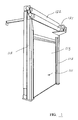
- Figure 1 is an oblique perspective view from the front of a thermally insulated door installation, having a double walled flexible curtain type door and which is shown in the closed position;
- Figure 2 is a view, similar to Figure 1, but showing the curtain in a partly raised position, in order to allow access to and from a refrigerated storage space;
- Figure 3 is a detail front view of the double walled curtain in a partly raised position (but with "break-out" tabs on the bottom edge or "blade" of the curtain door still engaged with the guides);
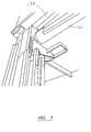
- Figure 4 illustrates an internal face of one of a pair of opposed vertical side frame members which define the side edges of the access opening, and with the door in the raised position (and showing a bottom edge or blade of the curtain door);
- Figure 5 is a perspective illustration corresponding to Figure 4, but before assembly of the blade;
- Figure 6 is a diagrammatic illustration of some of the essential components of the installation according to the invention; and
- Figure 7 illustrates a blower / dryer installation for providing a continuous supply of warm and dry air internally of the door and frame installation.
-
- Referring first to Figure 6 of the drawings, a thermally insulated access door installation according to the invention is designated generally by
reference 10 and comprises acurtain door 11 mounted in a frame defining an access opening to a refrigerated or cooled storage space (not shown). The frame includes a pair of upright frame members, of which one is shown byreference 12 in Figure 6, and which are horizontally spaced apart to define opposed sides of the required access opening. A double-walled flexible curtain forms thedoor 11, and having front andrear walls rear walls space 15 which receives a continuous supply of warm and dry air, when the curtain is closed, as will be described in more detail below. - Each
upright frame member 12 is provided with guide means (not shown in detail in Figure 6) and taking the form ofguide slots rear walls curtain 11. Thereby, the raising and lowering movement of thecurtain 11 can be guided. - A blower / dryer system shown diagrammatically in Figure 7 communicates with the
space 15 defined between the front andrear walls curtain 11, to deliver a supply of dry or at least low humidity air at a temperature greater than the temperature prevailing in the storage space. - Also, although not shown in detail, ducts or passages are provided in the
upright frame members 12, and which communicate with thespace 15 between the front andrear walls flexible curtain 11, when the curtain is in the closed position, in order also to receive the supply of dry warm air. - Therefore, in use of the
installation 10, dry and relatively warm air (which is at a higher temperature and lower humidity than the air prevailing in the storage space) can be supplied to thespace 15, and then routed internally of theupright frame members 12, and which minimises the risk of condensation forming internally of thecurtain 11 and theframe members 12, and also externally on the faces exposed to the chilled air in the storage space (and therefore minimize the risk of frost / ice forming on the exposed faces also). - The blower / dryer system shown in Figure 7, designated generally by
reference 18, is a closed loop system, comprisingblower 19 andhood 20 which supplies air to thespace 15 between thewalls space 15 and internally of theupright frame members 12, before being re-circulated after passing through any further treatment device which may be required (such as filtering / drying and warming unit shown by reference 30). - The double walled curtain 11 (front and
rear walls 13 and 14) is formed from a single strip of flexible material, which has each opposite end wound onto a horizontal support roller overlying the upper horizontal edge of the access opening, and from which the front andrear walls horizontal support roller 21 has the upper edge offront wall 13 connected thereto, so that thefront wall 13 can be wound and unwound relative toroller 21.Upper roller 22 serves the same function to wind and unwind therear wall 14. The front andrear walls common bottom edge 23, and which is strengthened by a horizontal bracing member, so as to form the bottom end of thecurtain 11 resting on the floor when the curtain is in the closed position. - The
curtain 11 is lightweight, and of low thermal capacity, and therefore is easily warmed to a higher temperature than the air in the storage space, so that condensation should not normally be deposited on the exposed faces of thecurtain 11 or theupright frame members 12. - In order to prevent damage to the door installation, in the event of accidental impact by a vehicle passing through the access opening when the curtain is in the raised position, it is preferred that the guidance between the
upright frame members 12 and the side edges of the front andrear walls - Figures 6 and 7 have been described above as schematic illustrations of the essential components of the preferred embodiment of the invention, and Figures 2 to 5 are illustrations of the constructional features of one preferred and more detailed embodiment of the invention. Parts corresponding with those already described with reference to Figure 6 are given the same reference numerals, but with the addition of 100. In particular, the
side frame members 112 are shown in more detail, and havingguide slots rear walls 113, 114 of curtain door 111. Also, ducts orpassages 131 are provided internally of theframe members 112, (to communicate via access openings in the front wall of eachframe member 112 with the internal space between thewalls 113, 114), and thereby allow routing of relatively warm and dry air internally of the frame members.
Claims (6)
- A thermally insulated access door installation (10) of a door (11) which is mounted in a frame (12) for defining an access opening to a refrigerated or cooled storage space, and which comprises:a pair of upright frame members (12) which are horizontally spaced apart to define opposed sides of the required access opening;a double-walled flexible curtain (11) which forms a closure door which can be raised and lowered between closed and open positions with respect to the access opening, and with a space (15) defined between the front and rear walls (13, 14) of the curtain (11);guide means (16, 17) provided on the upright frame members (12) and engaging the side edges of the front and rear walls (13, 14) of the curtain (11), for guiding the raising and lowering movement of the curtain;a blower (18) communicating with the space (15) defined between the front and rear walls (13, 14) of the curtain to deliver a supply of dry or at least low humidity air at a temperature greater than the temperature prevailing in the storage space; andducts or passages provided in the upright frame members (12) and communicating with the space (15) between the front and rear walls (13, 14) of the flexible curtain (11), when the latter is in the closed position, in order also to receive said supply of air.
- An installation according to claim 1, in which a closed loop blower / dryer system (18) is provided, operative to generate a continuous supply of warm air (relative to the temperature of the air in the storage space) and also dry air to the inter-wall space (15) of the curtain (11).
- An installation according to claim 2, including a further treatment device (30) operative to treat the air after passing through the upright members (12) and prior to recycling the air.
- An installation according to any one of the preceding claims, in which the double-walled curtain (11, 13, 14) is formed from a single strip of flexible material, which has each opposite end wound onto a horizontal support roller (21, 22) overlying the upper horizontal edge of the access opening and from which the front and rear walls (13, 14) hang downwardly and terminate in a common bottom edge (23).
- An installation according to claim 4, in which the bottom edge (23) has a horizontal bracing member.
- An installation according to claim 4, in which the guide means of each member (which engages corresponding side edges of the front and rear walls (13, 14) of the curtain (11)) also engages break-open tabs provided on the ends of the bottom edge (23) of the curtain (11) and which allows the curtain edge to disengage from the frame member in the event of an impact greater than a predetermined minimum, thereby to avoid damage being done to the curtain.
Applications Claiming Priority (2)
| Application Number | Priority Date | Filing Date | Title |
|---|---|---|---|
| GBGB0200360.6A GB0200360D0 (en) | 2002-01-09 | 2002-01-09 | Thermally insulated door for controlling access to a refrigerated storage space |
| GB0200360 | 2002-01-09 |
Publications (3)
| Publication Number | Publication Date |
|---|---|
| EP1327842A2 true EP1327842A2 (en) | 2003-07-16 |
| EP1327842A3 EP1327842A3 (en) | 2004-06-16 |
| EP1327842B1 EP1327842B1 (en) | 2021-04-07 |
Family
ID=9928774
Family Applications (1)
| Application Number | Title | Priority Date | Filing Date |
|---|---|---|---|
| EP03250025.8A Expired - Lifetime EP1327842B1 (en) | 2002-01-09 | 2003-01-06 | Thermally insulated door for controlling access to a refrigerated storage space |
Country Status (2)
| Country | Link |
|---|---|
| EP (1) | EP1327842B1 (en) |
| GB (2) | GB0200360D0 (en) |
Cited By (8)
| Publication number | Priority date | Publication date | Assignee | Title |
|---|---|---|---|---|
| WO2008129064A1 (en) * | 2007-04-24 | 2008-10-30 | C.M.V. Di Frati Mirco & Saimon & C. S.N.C. | Device for the thermal loss reduction |
| CN102116554A (en) * | 2010-01-04 | 2011-07-06 | Lg电子株式会社 | Refrigerator |
| DE102008014014B4 (en) * | 2007-03-16 | 2012-08-02 | Welita Gmbh | Through a high-speed door associated with it lamellae curtain to be closed access to a freezer compartment |
| ES2541791A1 (en) * | 2015-04-09 | 2015-07-24 | Control Y Accesos, S.L. | Double-canvas isothermal door (Machine-translation by Google Translate, not legally binding) |
| WO2017069713A1 (en) * | 2015-10-21 | 2017-04-27 | Bekir Tolga Sivritepe | High speed roll up door |
| US9803421B2 (en) | 2014-08-21 | 2017-10-31 | Troodon Torsysteme Gmbh | Door, in particular vertical-lift door, for closing an opening in a wall which separates two different temperature zones from one another |
| US20250002232A1 (en) * | 2021-10-29 | 2025-01-02 | Hefei Midea Refrigerator Co., Ltd. | Box device |
| US12584337B2 (en) | 2021-10-29 | 2026-03-24 | Hefei Midea Refrigerator Co., Ltd. | Cabinet device |
Families Citing this family (2)
| Publication number | Priority date | Publication date | Assignee | Title |
|---|---|---|---|---|
| GB0509919D0 (en) * | 2005-05-16 | 2005-06-22 | Ralph Ellerker 1795 Ltd | Improvements to door closure system |
| GB2526808B (en) * | 2014-06-03 | 2020-10-28 | Ralph Ellerker 1795 Ltd | Door system and method |
Citations (4)
| Publication number | Priority date | Publication date | Assignee | Title |
|---|---|---|---|---|
| GB1041406A (en) | 1963-04-19 | 1966-09-07 | Minikay Ltd | Improvements in or relating to air curtains |
| US5392836A (en) | 1992-06-23 | 1995-02-28 | Rite Hite Corporation | Door assembly |
| EP0816624A2 (en) | 1996-06-25 | 1998-01-07 | Cardo Continental B.V. | Quick moving door for cold-storage buildings |
| FR2799539A1 (en) | 1999-10-12 | 2001-04-13 | Ifi | Door, for cold storage warehouses or similar establishments, has arrangement which ensures smooth functioning of the doors |
Family Cites Families (5)
| Publication number | Priority date | Publication date | Assignee | Title |
|---|---|---|---|---|
| US5246053A (en) * | 1985-09-25 | 1993-09-21 | Nergeco | Riser for a vertically-opening door |
| ES2042355B1 (en) * | 1991-04-15 | 1994-06-01 | Darnaculleta Angel Mir | INDUSTRIAL USE DOOR. |
| US6226995B1 (en) * | 1998-06-24 | 2001-05-08 | Rytec Corporation | Frost control system for a door |
| US6155060A (en) * | 1999-11-05 | 2000-12-05 | Munters Corporation | Condensation and frost control system |
| US6474983B1 (en) * | 2001-04-30 | 2002-11-05 | Edward S. Robbins | Heated industrial curtain |
-
2002
- 2002-01-09 GB GBGB0200360.6A patent/GB0200360D0/en not_active Ceased
-
2003
- 2003-01-06 GB GB0300151.8A patent/GB2385659C/en not_active Expired - Lifetime
- 2003-01-06 EP EP03250025.8A patent/EP1327842B1/en not_active Expired - Lifetime
Patent Citations (4)
| Publication number | Priority date | Publication date | Assignee | Title |
|---|---|---|---|---|
| GB1041406A (en) | 1963-04-19 | 1966-09-07 | Minikay Ltd | Improvements in or relating to air curtains |
| US5392836A (en) | 1992-06-23 | 1995-02-28 | Rite Hite Corporation | Door assembly |
| EP0816624A2 (en) | 1996-06-25 | 1998-01-07 | Cardo Continental B.V. | Quick moving door for cold-storage buildings |
| FR2799539A1 (en) | 1999-10-12 | 2001-04-13 | Ifi | Door, for cold storage warehouses or similar establishments, has arrangement which ensures smooth functioning of the doors |
Non-Patent Citations (3)
| Title |
|---|
| CLARK DOOR LTD: "Conditioned air freezer door", BROCHURE, pages 2 PG-S, XP002997843 |
| HCR INCORPORATED: "Model ECAV frost-free airlok-door", INSTRUCTION MANUAL, 1998, pages 1 - 41, XP002997841 |
| SMITH G.R.: "Freezer vestibules", HANDOUT FOR A PRESENTATION AT THE 20TH ANNUAL DESIGN SEMINAR, 2 February 1998 (1998-02-02) - 6 February 1998 (1998-02-06), pages 1 - 30 + COVER&INDEX, XP002997842 |
Cited By (10)
| Publication number | Priority date | Publication date | Assignee | Title |
|---|---|---|---|---|
| DE102008014014B4 (en) * | 2007-03-16 | 2012-08-02 | Welita Gmbh | Through a high-speed door associated with it lamellae curtain to be closed access to a freezer compartment |
| WO2008129064A1 (en) * | 2007-04-24 | 2008-10-30 | C.M.V. Di Frati Mirco & Saimon & C. S.N.C. | Device for the thermal loss reduction |
| CN102116554A (en) * | 2010-01-04 | 2011-07-06 | Lg电子株式会社 | Refrigerator |
| US9803421B2 (en) | 2014-08-21 | 2017-10-31 | Troodon Torsysteme Gmbh | Door, in particular vertical-lift door, for closing an opening in a wall which separates two different temperature zones from one another |
| ES2541791A1 (en) * | 2015-04-09 | 2015-07-24 | Control Y Accesos, S.L. | Double-canvas isothermal door (Machine-translation by Google Translate, not legally binding) |
| WO2016162583A1 (en) * | 2015-04-09 | 2016-10-13 | Control Y Accesos, S.L. | Double-canvas insulated door |
| WO2017069713A1 (en) * | 2015-10-21 | 2017-04-27 | Bekir Tolga Sivritepe | High speed roll up door |
| US20250002232A1 (en) * | 2021-10-29 | 2025-01-02 | Hefei Midea Refrigerator Co., Ltd. | Box device |
| US12497216B2 (en) * | 2021-10-29 | 2025-12-16 | Hefei Midea Refrigerator Co., Ltd. | Box device |
| US12584337B2 (en) | 2021-10-29 | 2026-03-24 | Hefei Midea Refrigerator Co., Ltd. | Cabinet device |
Also Published As
| Publication number | Publication date |
|---|---|
| EP1327842A3 (en) | 2004-06-16 |
| GB2385659C (en) | 2015-03-11 |
| GB2385659A (en) | 2003-08-27 |
| GB0300151D0 (en) | 2003-02-05 |
| GB0200360D0 (en) | 2002-02-20 |
| GB2385659B (en) | 2006-02-15 |
| EP1327842B1 (en) | 2021-04-07 |
Similar Documents
| Publication | Publication Date | Title |
|---|---|---|
| RU2259520C2 (en) | Cooling chamber | |
| EP1327842B1 (en) | Thermally insulated door for controlling access to a refrigerated storage space | |
| US7338239B2 (en) | System and method for partitioning cargo areas | |
| JP2000504100A (en) | Composition of refrigeration container | |
| JP2016027294A (en) | Refrigerator | |
| JP2009036496A (en) | Rack and air curtain device operating method for a freezer / refrigerated warehouse | |
| JP2003156282A (en) | Gate device for closure of passage between plural rooms of remarkably different temperature | |
| JPWO2020004346A1 (en) | Heat storage material unit and vending machine equipped with this heat storage material unit | |
| SE504556C2 (en) | Cooling units for refrigeration containers | |
| JP2005187201A (en) | Warehouse type refrigerator | |
| JP5555539B2 (en) | Mobile sales car | |
| JP3841324B2 (en) | Refrigerated / refrigerated open showcase | |
| JP3761234B2 (en) | vending machine | |
| JPH05193346A (en) | Cold reserving device inside storehouse for cold reserving storehouse on vehicle | |
| JPH0610775U (en) | In-vehicle mobile refrigerator | |
| JP3266237B2 (en) | Storage room partitioning device | |
| JPH07190581A (en) | How to control the temperature of the freezer refrigeration open showcase | |
| JP4169877B2 (en) | Cold storage | |
| CN218431020U (en) | Cold chain commodity circulation is with circulation refrigeration formula refrigerator car that fresh-keeping effect is excellent | |
| JP3887940B2 (en) | vending machine | |
| JPS6113893Y2 (en) | ||
| JPH0338616Y2 (en) | ||
| JP2783878B2 (en) | Cold storage | |
| JPH0618184Y2 (en) | Frozen and refrigerated food display device | |
| JPS5872865A (en) | Refrigerating open showcase |
Legal Events
| Date | Code | Title | Description |
|---|---|---|---|
| PUAI | Public reference made under article 153(3) epc to a published international application that has entered the european phase |
Free format text: ORIGINAL CODE: 0009012 |
|
| AK | Designated contracting states |
Designated state(s): AT BE BG CH CY CZ DE DK EE ES FI FR GB GR HU IE IT LI LU MC NL PT SE SI SK TR |
|
| AX | Request for extension of the european patent |
Extension state: AL LT LV MK RO |
|
| PUAL | Search report despatched |
Free format text: ORIGINAL CODE: 0009013 |
|
| AK | Designated contracting states |
Kind code of ref document: A3 Designated state(s): AT BE BG CH CY CZ DE DK EE ES FI FR GB GR HU IE IT LI LU MC NL PT SE SI SK TR |
|
| AX | Request for extension of the european patent |
Extension state: AL LT LV MK RO |
|
| RIC1 | Information provided on ipc code assigned before grant |
Ipc: 7E 06B 3/44 B Ipc: 7F 25D 23/02 A |
|
| 17P | Request for examination filed |
Effective date: 20040707 |
|
| AKX | Designation fees paid |
Designated state(s): AT BE BG CH CY CZ DE DK EE ES FI FR GB GR HU IE IT LI LU MC NL PT SE SI SK TR |
|
| TPAC | Observations filed by third parties |
Free format text: ORIGINAL CODE: EPIDOSNTIPA |
|
| RAP1 | Party data changed (applicant data changed or rights of an application transferred) |
Owner name: RALPH ELLERKER (1795) LTD |
|
| STAA | Information on the status of an ep patent application or granted ep patent |
Free format text: STATUS: EXAMINATION IS IN PROGRESS |
|
| REG | Reference to a national code |
Ref country code: DE Ref legal event code: R079 Ref document number: 60352634 Country of ref document: DE Free format text: PREVIOUS MAIN CLASS: F25D0023020000 Ipc: E06B0009130000 |
|
| GRAP | Despatch of communication of intention to grant a patent |
Free format text: ORIGINAL CODE: EPIDOSNIGR1 |
|
| STAA | Information on the status of an ep patent application or granted ep patent |
Free format text: STATUS: GRANT OF PATENT IS INTENDED |
|
| RIC1 | Information provided on ipc code assigned before grant |
Ipc: F25D 23/02 20060101ALI20201015BHEP Ipc: E06B 9/13 20060101AFI20201015BHEP Ipc: E06B 3/44 20060101ALI20201015BHEP |
|
| INTG | Intention to grant announced |
Effective date: 20201106 |
|
| GRAS | Grant fee paid |
Free format text: ORIGINAL CODE: EPIDOSNIGR3 |
|
| GRAA | (expected) grant |
Free format text: ORIGINAL CODE: 0009210 |
|
| STAA | Information on the status of an ep patent application or granted ep patent |
Free format text: STATUS: THE PATENT HAS BEEN GRANTED |
|
| REG | Reference to a national code |
Ref country code: DE Ref legal event code: R081 Ref document number: 60352634 Country of ref document: DE Owner name: RALPH ELLERKER (1795) LTD., GB Free format text: FORMER OWNER: SCHOFIELD, CHRISTINE ISABEL, C/O UNION INDUSTRIES, HUNSLET, LEEDS, GB |
|
| AK | Designated contracting states |
Kind code of ref document: B1 Designated state(s): AT BE BG CH CY CZ DE DK EE ES FI FR GB GR HU IE IT LI LU MC NL PT SE SI SK TR |
|
| REG | Reference to a national code |
Ref country code: GB Ref legal event code: FG4D |
|
| REG | Reference to a national code |
Ref country code: AT Ref legal event code: REF Ref document number: 1379900 Country of ref document: AT Kind code of ref document: T Effective date: 20210415 Ref country code: CH Ref legal event code: EP |
|
| REG | Reference to a national code |
Ref country code: DE Ref legal event code: R096 Ref document number: 60352634 Country of ref document: DE |
|
| REG | Reference to a national code |
Ref country code: IE Ref legal event code: FG4D |
|
| REG | Reference to a national code |
Ref country code: NL Ref legal event code: MP Effective date: 20210407 Ref country code: AT Ref legal event code: MK05 Ref document number: 1379900 Country of ref document: AT Kind code of ref document: T Effective date: 20210407 |
|
| PG25 | Lapsed in a contracting state [announced via postgrant information from national office to epo] |
Ref country code: BG Free format text: LAPSE BECAUSE OF FAILURE TO SUBMIT A TRANSLATION OF THE DESCRIPTION OR TO PAY THE FEE WITHIN THE PRESCRIBED TIME-LIMIT Effective date: 20210707 Ref country code: AT Free format text: LAPSE BECAUSE OF FAILURE TO SUBMIT A TRANSLATION OF THE DESCRIPTION OR TO PAY THE FEE WITHIN THE PRESCRIBED TIME-LIMIT Effective date: 20210407 Ref country code: FI Free format text: LAPSE BECAUSE OF FAILURE TO SUBMIT A TRANSLATION OF THE DESCRIPTION OR TO PAY THE FEE WITHIN THE PRESCRIBED TIME-LIMIT Effective date: 20210407 Ref country code: NL Free format text: LAPSE BECAUSE OF FAILURE TO SUBMIT A TRANSLATION OF THE DESCRIPTION OR TO PAY THE FEE WITHIN THE PRESCRIBED TIME-LIMIT Effective date: 20210407 |
|
| PG25 | Lapsed in a contracting state [announced via postgrant information from national office to epo] |
Ref country code: GR Free format text: LAPSE BECAUSE OF FAILURE TO SUBMIT A TRANSLATION OF THE DESCRIPTION OR TO PAY THE FEE WITHIN THE PRESCRIBED TIME-LIMIT Effective date: 20210708 Ref country code: SE Free format text: LAPSE BECAUSE OF FAILURE TO SUBMIT A TRANSLATION OF THE DESCRIPTION OR TO PAY THE FEE WITHIN THE PRESCRIBED TIME-LIMIT Effective date: 20210407 Ref country code: PT Free format text: LAPSE BECAUSE OF FAILURE TO SUBMIT A TRANSLATION OF THE DESCRIPTION OR TO PAY THE FEE WITHIN THE PRESCRIBED TIME-LIMIT Effective date: 20210809 Ref country code: ES Free format text: LAPSE BECAUSE OF FAILURE TO SUBMIT A TRANSLATION OF THE DESCRIPTION OR TO PAY THE FEE WITHIN THE PRESCRIBED TIME-LIMIT Effective date: 20210407 |
|
| REG | Reference to a national code |
Ref country code: DE Ref legal event code: R097 Ref document number: 60352634 Country of ref document: DE |
|
| PG25 | Lapsed in a contracting state [announced via postgrant information from national office to epo] |
Ref country code: SK Free format text: LAPSE BECAUSE OF FAILURE TO SUBMIT A TRANSLATION OF THE DESCRIPTION OR TO PAY THE FEE WITHIN THE PRESCRIBED TIME-LIMIT Effective date: 20210407 Ref country code: EE Free format text: LAPSE BECAUSE OF FAILURE TO SUBMIT A TRANSLATION OF THE DESCRIPTION OR TO PAY THE FEE WITHIN THE PRESCRIBED TIME-LIMIT Effective date: 20210407 Ref country code: CZ Free format text: LAPSE BECAUSE OF FAILURE TO SUBMIT A TRANSLATION OF THE DESCRIPTION OR TO PAY THE FEE WITHIN THE PRESCRIBED TIME-LIMIT Effective date: 20210407 Ref country code: DK Free format text: LAPSE BECAUSE OF FAILURE TO SUBMIT A TRANSLATION OF THE DESCRIPTION OR TO PAY THE FEE WITHIN THE PRESCRIBED TIME-LIMIT Effective date: 20210407 |
|
| PLBE | No opposition filed within time limit |
Free format text: ORIGINAL CODE: 0009261 |
|
| STAA | Information on the status of an ep patent application or granted ep patent |
Free format text: STATUS: NO OPPOSITION FILED WITHIN TIME LIMIT |
|
| 26N | No opposition filed |
Effective date: 20220110 |
|
| PGFP | Annual fee paid to national office [announced via postgrant information from national office to epo] |
Ref country code: GB Payment date: 20220111 Year of fee payment: 20 Ref country code: DE Payment date: 20220112 Year of fee payment: 20 |
|
| PGFP | Annual fee paid to national office [announced via postgrant information from national office to epo] |
Ref country code: FR Payment date: 20220111 Year of fee payment: 20 |
|
| PG25 | Lapsed in a contracting state [announced via postgrant information from national office to epo] |
Ref country code: IT Free format text: LAPSE BECAUSE OF FAILURE TO SUBMIT A TRANSLATION OF THE DESCRIPTION OR TO PAY THE FEE WITHIN THE PRESCRIBED TIME-LIMIT Effective date: 20210407 |
|
| PG25 | Lapsed in a contracting state [announced via postgrant information from national office to epo] |
Ref country code: MC Free format text: LAPSE BECAUSE OF FAILURE TO SUBMIT A TRANSLATION OF THE DESCRIPTION OR TO PAY THE FEE WITHIN THE PRESCRIBED TIME-LIMIT Effective date: 20210407 |
|
| REG | Reference to a national code |
Ref country code: CH Ref legal event code: PL |
|
| REG | Reference to a national code |
Ref country code: BE Ref legal event code: MM Effective date: 20220131 |
|
| PG25 | Lapsed in a contracting state [announced via postgrant information from national office to epo] |
Ref country code: LU Free format text: LAPSE BECAUSE OF NON-PAYMENT OF DUE FEES Effective date: 20220106 |
|
| PG25 | Lapsed in a contracting state [announced via postgrant information from national office to epo] |
Ref country code: BE Free format text: LAPSE BECAUSE OF NON-PAYMENT OF DUE FEES Effective date: 20220131 |
|
| PG25 | Lapsed in a contracting state [announced via postgrant information from national office to epo] |
Ref country code: LI Free format text: LAPSE BECAUSE OF NON-PAYMENT OF DUE FEES Effective date: 20220131 Ref country code: CH Free format text: LAPSE BECAUSE OF NON-PAYMENT OF DUE FEES Effective date: 20220131 |
|
| REG | Reference to a national code |
Ref country code: DE Ref legal event code: R071 Ref document number: 60352634 Country of ref document: DE |
|
| REG | Reference to a national code |
Ref country code: GB Ref legal event code: PE20 Expiry date: 20230105 |
|
| PG25 | Lapsed in a contracting state [announced via postgrant information from national office to epo] |
Ref country code: IE Free format text: LAPSE BECAUSE OF NON-PAYMENT OF DUE FEES Effective date: 20220106 |
|
| PG25 | Lapsed in a contracting state [announced via postgrant information from national office to epo] |
Ref country code: GB Free format text: LAPSE BECAUSE OF EXPIRATION OF PROTECTION Effective date: 20230105 |
|
| PG25 | Lapsed in a contracting state [announced via postgrant information from national office to epo] |
Ref country code: HU Free format text: LAPSE BECAUSE OF FAILURE TO SUBMIT A TRANSLATION OF THE DESCRIPTION OR TO PAY THE FEE WITHIN THE PRESCRIBED TIME-LIMIT; INVALID AB INITIO Effective date: 20030106 |
|
| PG25 | Lapsed in a contracting state [announced via postgrant information from national office to epo] |
Ref country code: CY Free format text: LAPSE BECAUSE OF FAILURE TO SUBMIT A TRANSLATION OF THE DESCRIPTION OR TO PAY THE FEE WITHIN THE PRESCRIBED TIME-LIMIT Effective date: 20210407 |
|
| PG25 | Lapsed in a contracting state [announced via postgrant information from national office to epo] |
Ref country code: TR Free format text: LAPSE BECAUSE OF FAILURE TO SUBMIT A TRANSLATION OF THE DESCRIPTION OR TO PAY THE FEE WITHIN THE PRESCRIBED TIME-LIMIT Effective date: 20210407 |