JP2009036496A - Rack for freezing-refrigerating warehouse and operation method of air curtain device - Google Patents
Rack for freezing-refrigerating warehouse and operation method of air curtain device Download PDFInfo
- Publication number
- JP2009036496A JP2009036496A JP2007203459A JP2007203459A JP2009036496A JP 2009036496 A JP2009036496 A JP 2009036496A JP 2007203459 A JP2007203459 A JP 2007203459A JP 2007203459 A JP2007203459 A JP 2007203459A JP 2009036496 A JP2009036496 A JP 2009036496A
- Authority
- JP
- Japan
- Prior art keywords
- blower
- air
- rack
- temperature zone
- area
- Prior art date
- Legal status (The legal status is an assumption and is not a legal conclusion. Google has not performed a legal analysis and makes no representation as to the accuracy of the status listed.)
- Granted
Links
- 238000000034 method Methods 0.000 title claims description 9
- 238000007710 freezing Methods 0.000 claims abstract description 21
- 230000008014 freezing Effects 0.000 claims abstract description 21
- 238000005057 refrigeration Methods 0.000 claims description 28
- 230000000903 blocking effect Effects 0.000 claims description 3
- 238000001816 cooling Methods 0.000 claims description 3
- 230000000694 effects Effects 0.000 abstract description 10
- 238000009434 installation Methods 0.000 abstract description 3
- 238000005192 partition Methods 0.000 description 17
- 238000001514 detection method Methods 0.000 description 5
- 239000002184 metal Substances 0.000 description 4
- 229910001220 stainless steel Inorganic materials 0.000 description 3
- 239000010935 stainless steel Substances 0.000 description 3
- 230000002411 adverse Effects 0.000 description 1
- 238000010586 diagram Methods 0.000 description 1
- 238000009792 diffusion process Methods 0.000 description 1
- 239000000463 material Substances 0.000 description 1
- 238000002844 melting Methods 0.000 description 1
- 230000008018 melting Effects 0.000 description 1
- 230000002265 prevention Effects 0.000 description 1
- 230000000087 stabilizing effect Effects 0.000 description 1
- 125000000391 vinyl group Chemical group [H]C([*])=C([H])[H] 0.000 description 1
- 229920002554 vinyl polymer Polymers 0.000 description 1
Images


Abstract
Description
本発明は、ラックに保管された商品を注文に応じてピッキングしコールドボックスに詰める仕分け作業、いわゆるピッキング作業に適した冷凍冷蔵倉庫に関し、特に、エアカーテン装置を備えたラックと、エアカーテン装置の運転方法に関するものである。 The present invention relates to a freezing and refrigeration warehouse suitable for sorting work in which goods stored in a rack are picked up according to an order and packed in a cold box, so-called picking work, and in particular, a rack equipped with an air curtain device and an air curtain device It relates to the driving method.
スーパーマーケットやレストランに配送される食品等の商品の多くは冷凍され、冷凍倉庫のラックにて一時的に保管されるのが一般的である。この冷凍商品を出荷する際の仕分け作業、いわゆるピッキング作業は、従来、冷凍温度帯(零下、好ましくは−10℃〜−25℃程度)の冷凍倉庫内で行われ、或いは、一旦、冷凍倉庫から冷凍商品を冷蔵温度帯(零度以上の低温、好ましくは+5℃程度)の冷蔵倉庫に移動させた後、そこで行われていた。 Many products such as food delivered to supermarkets and restaurants are generally frozen and temporarily stored in a freezer rack. Sorting operations when shipping frozen products, so-called picking operations, are conventionally performed in a freezing warehouse in a freezing temperature zone (below zero, preferably about −10 ° C. to −25 ° C.) or once from a freezing warehouse. This was done after moving the frozen product to a refrigerated warehouse in a refrigerated temperature zone (low temperature above zero degree, preferably about + 5 ° C.).
しかしながら、冷凍倉庫内でのピッキング作業は作業者にとって負荷が大きく、効率が悪いという問題点があった。 However, picking work in a freezer warehouse has a problem that it is heavy on the operator and is inefficient.
また、冷蔵倉庫内でのピッキング作業は、作業者には負荷軽減となるが、冷凍商品に対しては品質低下を招くおそれがある。 In addition, the picking operation in the refrigerated warehouse reduces the load on the operator, but there is a risk that the quality of the frozen product is deteriorated.
このため、従来においては、下記の特許文献1に開示されているように、倉庫内を冷凍温度帯のエリア(以下「低温エリア」という)と冷蔵温度帯のエリア(以下「高温エリア」)とに分割し、商品を保管するラックを低温エリアに配置すると共に、高温エリアに対してラックの商品取出し口を向け、高温エリアで作業者が短時間でピッキング作業を完了させることができるようにした冷凍冷蔵倉庫が知られている。 For this reason, conventionally, as disclosed in the following Patent Document 1, the warehouse is divided into a freezing temperature zone area (hereinafter referred to as “low temperature area”) and a refrigeration temperature zone area (hereinafter referred to as “high temperature area”). The rack for storing products is arranged in the low temperature area, and the rack product outlet is directed to the high temperature area so that workers can complete the picking work in a short time in the high temperature area. Refrigerated warehouse is known.
また、特許文献1に記載の冷凍冷蔵倉庫においては、低温エリアと高温エリアとを仕切るために、エアカーテン装置が用いられている。エアカーテン装置は、低温エリアと高温エリアとを仕切るために倉庫建屋の天井からラック近くまで垂下された仕切り壁(鴨居状の壁)に取り付けられている。また、エアカーテン効果を高めるために、エアカーテン装置は、低温エリア側で上方から床面方向に向けて低温エリアと同等の温度の冷風を吹き出す第1の送風機と、高温エリア側で上方から床面方向に向けて高温エリアと同等の温度の冷風を吹き出す第2の送風機とから構成されており、これらの送風機は仕切り壁を挟む形で仕切り壁に取り付けられている。
しかしながら、上述したような従来の冷凍冷蔵倉庫においては、エアカーテン装置を倉庫建屋の仕切り壁に取り付けることとしているので、その設置工事は大掛かりなものとなる。 However, in the conventional refrigerator-freezer warehouse as described above, since the air curtain device is attached to the partition wall of the warehouse building, the installation work becomes large.
また、低温エリアと高温エリアとの間の境界部全域にエアカーテン装置を設置しなければならず、多数のエアカーテン装置が必要であり、省エネルギーの面からも好ましくない。 In addition, an air curtain device must be installed over the entire boundary between the low temperature area and the high temperature area, which requires a large number of air curtain devices, which is not preferable from the viewpoint of energy saving.
更に、エアカーテン装置の第1の送風機と第2の送風機との間には仕切り壁があるため、これらの送風機から吐出される冷風の層間に乱流が生じやすく、そのために冷風の風速制御が困難であり、また、流れ安定用の楔形パネルを第1と第2の送風機間に設ける必要があった。 Further, since there is a partition wall between the first blower and the second blower of the air curtain device, turbulent flow is likely to occur between the layers of the cold air discharged from these blowers, so that the wind speed control of the cold air is controlled. It was difficult, and it was necessary to provide a wedge-shaped panel for stabilizing the flow between the first and second blowers.
本発明の目的は上記問題点を解決することにある。 An object of the present invention is to solve the above problems.
前記目的を達成するために、本発明は、冷凍温度帯のエリア(低温エリア)と、冷凍温度帯よりも高温の冷蔵温度帯のエリア(高温エリア)とに分割されている冷凍冷蔵倉庫内にて、前記低温エリアに設置される、冷凍商品を保管するためのラックにおいて、低温エリアと高温エリアとの間とを二層の空気流によって遮断するエアカーテン装置が取り付けられており、このエアカーテン装置が、
a.低温エリア内の空気を取り入れて吐出する第1の送風機、及び、高温エリア内の空気を取り入れて吐出すると共に、吐出口が第1の送風機の吐出口に隣接配置されている第2の送風機からなる、当該ラックの最上部に取り付けられる上部ユニットと、
b.当該ラックの最下部に配置され、第1の送風機からの空気流を吸引して低温エリアに戻す下部ユニットと、
を備えることを特徴としている。
In order to achieve the above object, the present invention provides a refrigeration warehouse that is divided into a freezing temperature zone area (low temperature area) and a refrigerating temperature zone area (high temperature area) higher than the freezing temperature zone. In the rack for storing frozen products installed in the low temperature area, an air curtain device is installed to block between the low temperature area and the high temperature area by a two-layer air flow. The device
a. From the first blower that takes in and discharges air in the low-temperature area and the second blower that takes in and discharges air in the high-temperature area and the discharge port is disposed adjacent to the discharge port of the first blower An upper unit attached to the top of the rack,
b. A lower unit disposed at the bottom of the rack, for sucking the airflow from the first blower and returning it to the low temperature area;
It is characterized by having.
かかる構成においては、エアカーテン装置はラックと一体となっているため、倉庫の仕切り壁にエアカーテン装置を取り付ける工事が不要である。また、ラック毎にエアカーテンを形成することになるので、エアカーテンが不要な位置にエアカーテン装置を設ける必要もない。更に、第1の送風機の吐出口と第2の送風機の吐出口が隣接配置されるので、空気流に乱れが生ずる可能性が低くなる。 In such a configuration, since the air curtain device is integrated with the rack, it is not necessary to install the air curtain device on the partition wall of the warehouse. Further, since an air curtain is formed for each rack, it is not necessary to provide an air curtain device at a position where no air curtain is required. Furthermore, since the discharge port of the first blower and the discharge port of the second blower are disposed adjacent to each other, the possibility that the air flow is disturbed is reduced.
また、第1の送風機は、水平方向に延びる第1ダクト部から空気を取り入れて、上下方向に延びる第2ダクト部の下部開口部から空気を吐出するよう構成されていることが好ましい。この構成では、第1ダクト部を仕切り壁の下を通すことが可能となり、ラックの設置が容易となる。 Moreover, it is preferable that the 1st air blower is comprised so that air may be taken in from the 1st duct part extended in a horizontal direction, and air may be discharged from the lower opening part of the 2nd duct part extended in an up-down direction. In this configuration, the first duct portion can be passed under the partition wall, and the rack can be easily installed.
また、取り出すべき冷凍商品を指示するための表示器を、第2の送風機から吐出された空気流から高温エリアまでの間に位置するようにラックに取り付けることが有効である。零下の空気による悪影響から保護するためである。 It is also effective to attach an indicator for indicating a frozen product to be taken out to the rack so as to be positioned between the air flow discharged from the second blower and the high temperature area. This is to protect against the adverse effects of air below zero.
更に、ラックの各段に、商品取出し口に隣接する位置に暖簾状の遮断手段を設けることが好適である。エアカーテンと共に、より低温エリアと高温エリアとの間の遮断効率を上げるためである。 Furthermore, it is preferable to provide a warm shut-off means at each position of the rack adjacent to the product outlet. This is because, together with the air curtain, the blocking efficiency between the lower temperature area and the higher temperature area is increased.
また、本発明の第2の態様によれば、低温エリアと、前記冷凍温度帯よりも高温の高温エリアとに分割されている冷凍冷蔵倉庫内にて、低温エリアに設置されたラックに関して、低温エリアと高温エリアとの間を二層の空気流によって遮断すべく設けられたエアカーテン装置の運転方法において、エアカーテン装置を、上述の第1の送風機及び第2の送風機からなる上部ユニットと、第1の送風機からの空気流を吸引して低温エリアに戻す下部ユニットとを備えるものとし、その上で、第1の送風機からの空気流の風速と第2の送風機からの空気流の風速とを3.5〜6.0m/sの範囲としたことを特徴とする。この運転方法では、エアカーテン効果が十分に発揮される。 Further, according to the second aspect of the present invention, the rack installed in the low-temperature area in the freezer / refrigeration warehouse divided into the low-temperature area and the high-temperature area higher than the refrigeration temperature zone has a low temperature. In the operation method of the air curtain device provided to block between the area and the high temperature area by the two-layer air flow, the air curtain device includes the upper unit composed of the first blower and the second blower described above, A lower unit that sucks the airflow from the first blower and returns it to the low-temperature area, on which the airflow velocity from the first blower and the airflow velocity from the second blower are Is in the range of 3.5 to 6.0 m / s. In this operation method, the air curtain effect is sufficiently exhibited.
また、各空気流の幅がエアカーテン効果を得るのに十分となるよう、第1の送風機の吐出口の幅を50mm以上とすることが有効である。 In addition, it is effective to set the width of the discharge port of the first blower to 50 mm or more so that the width of each air flow is sufficient to obtain the air curtain effect.
なお、作業員の人数や倉庫内の商品占有率等の環境の変化に対応すべく、低温エリアを冷却するための冷却器の運転負荷を検出する負荷検出手段を設け、第1の送風機からの空気流の風速と第2の送風機からの空気流の風速とを検出する風速検出手段を設け、負荷検出手段から冷却器の運転負荷が所定範囲内にあるように、風速検出手段からの風速の検出値に従って第1の送風機からの空気流の風速と第2の送風機からの空気流の風速を制御すると共に、第1の送風機からの空気流と同量で空気を吸引するよう下部ユニットを制御するとよい。下部ユニットを制御することとしたのは、吸引量が少ない場合には、第1の送風機からの冷凍温度帯の空気流が下部ユニットで回収されず、効率が減少し、逆に多い場合には、冷蔵温度帯の空気まで低温エリアに送られ、冷凍機の負担が増加するためである。 In addition, in order to respond to changes in the environment such as the number of workers and the product occupancy rate in the warehouse, load detection means for detecting the operation load of the cooler for cooling the low temperature area is provided. Wind speed detection means for detecting the wind speed of the air flow and the wind speed of the air flow from the second blower is provided, and the wind speed from the wind speed detection means is adjusted so that the operating load of the cooler is within a predetermined range from the load detection means. Controls the wind speed of the air flow from the first blower and the wind speed of the air flow from the second blower according to the detected value, and controls the lower unit to suck air in the same amount as the air flow from the first blower. Good. The reason for controlling the lower unit is that when the suction amount is small, the air flow in the refrigeration temperature zone from the first blower is not collected by the lower unit, and the efficiency is reduced. This is because the air in the refrigerated temperature zone is sent to the low temperature area and the burden on the refrigerator increases.
上述したように、本発明の冷凍冷蔵倉庫用のラックによれば、エアカーテン装置はラックと一体となっているため、倉庫の仕切り壁にエアカーテン装置を取り付ける工事が不要となり、設置工事が容易となり、また種々の倉庫にも対応しやすくなる。 As described above, according to the rack for a refrigerator warehouse of the present invention, since the air curtain device is integrated with the rack, it is not necessary to install the air curtain device on the partition wall of the warehouse, and the installation work is easy. In addition, it becomes easy to deal with various warehouses.
また、ラック毎にエアカーテンを形成することになるので、エアカーテンが不要な位置にエアカーテン装置を設ける必要がなく、省エネルギーの観点から有効である。 In addition, since an air curtain is formed for each rack, it is not necessary to provide an air curtain device at a position where the air curtain is unnecessary, which is effective from the viewpoint of energy saving.
更に、第1の送風機の吐出口と第2の送風機の吐出口が隣接配置されるので、空気流に乱れが生ずる可能性が低くなり、エアカーテン効果が向上する。 Furthermore, since the discharge port of the first blower and the discharge port of the second blower are arranged adjacent to each other, the possibility that the air flow is disturbed is reduced, and the air curtain effect is improved.
本発明のエアカーテン装置の運転方法によって、このエアカーテン効果を確実に得ることができる。 The air curtain effect can be reliably obtained by the operation method of the air curtain device of the present invention.
以下、図面と共に本発明の好適な実施形態について詳細に説明する。 DESCRIPTION OF EMBODIMENTS Hereinafter, preferred embodiments of the present invention will be described in detail with reference to the drawings.
図1は、本発明によるラックとしてのフローラック10が設置された冷凍冷蔵倉庫12の一例を示す図である。図示するように、この冷凍冷蔵倉庫12は、冷凍商品14を保管するための低温エリア(冷凍温度帯エリア)16と、作業員がピッキング作業を行う高温エリア(冷蔵温度帯エリア)18とを有し、両エリア16,18は、倉庫建屋の天井20から所定の長さで垂下された仕切り壁22により仕切られている。低温エリア16は、図示しない冷却器により、冷凍商品14を保管するために適した温度、すなわち零度以下であり、好ましくは−10℃〜−25℃程度に保たれるようになっている。また、高温エリア18は、別の冷却器(図示しない)によって零度以上に保たれるが、その温度は、低温エリア16から取り出された冷凍商品14の融解を極力抑え、かつ、作業者への負荷を低減するため、約+5℃程度が好ましい。床面24から仕切り壁22までの高さは、フローラック10の全高よりも大きくされている。
FIG. 1 is a diagram showing an example of a freezer / refrigerated
フローラック10は、図2にも示されるように、左右のサイドフレーム26と、これらのサイドフレーム26間に横架された棚28とを備えている。棚28は上下方向に複数段、配置されている。各棚28は、前後方向に延びるローラコンベヤないしはホイールコンベヤ30を備え、その上に載置された冷凍商品14が自重により移動するよう、一方向に向かって下方に傾斜されている。以下、この方向を前方と称する(図1においては左方向)。冷凍商品14は各棚28の前方の終端縁にて停止し、そこが商品取出し口32となる。なお、本実施形態においては、商品14の取出しが容易となるよう、下方の棚28の終端縁ほど前方に突出している。
As shown in FIG. 2, the
更に、フローラック10における左右のサイドフレーム26の上部間には、前後それぞれに、支持ビーム34,36が横架されている。前側の支持ビーム34にはエアカーテン装置38の上部ユニット40が固定される。
Further,
エアカーテン装置38の上部ユニット40は、図2からも理解されるように、2つの送風機42,44から構成されている。第1の送風機42は、フローラック10を冷凍冷蔵倉庫12内の所定位置(図1の位置)に設置した状態において、仕切り壁22とフローラック10との間の間隙に置かれ、第2の送風機44が仕切り壁22の前面に接する位置に配置されるようになっている。
The
第1の送風機42は、水平に延びる第1ダクト部46aと、この第1ダクト部46aの前方に配置され下方に延びる第2ダクト部46bと、これらの第1と第2のダクト部46a,46b間を接続する湾曲ダクト部46cとから構成されている。これらのダクト部46a〜46cはステンレススチール等の金属の薄板から構成されていることが好ましい。また、第1ダクト部46aの後部開口部には、複数の送風ファン48を有するファンユニット50が取り付けられている。この送風ファン48を作動させることで、空気を後方から取り入れ、その空気を第1ダクト部46aから湾曲ダクト部46cを経て、第2ダクト部46bの下部開口部(吐出口)46dから下方に吐出することができる。
The
第2の送風機44は、上下方向に延びるダクト部52を備え、その上部開口部には、空気を上方から吸引して下方に流すべく、複数の送風ファン54を有するファンユニット56が取り付けられている。このダクト部52もステンレススチール等の金属薄板からなるが、その後面の下部部分52aは、第1の送風機42における湾曲ダクト部46cと第2ダクト部46bの前面を構成する金属薄板を共用している。ダクト部52の後面の上部部分52bは垂直に延び、仕切り壁22と密着する。また、第2の送風機44におけるダクト部52の前面は、第1の送風機42における第2ダクト部46cの前面と実質的に平行となっており、ダクト部52の下部開口部(吐出口)52cから吐出される空気流は第1の送風機42から吐出される空気流と実質的に平行となる。
The
このようなエアカーテン装置38の上部ユニット40は、第1ダクト部46aをフローラック10の前部支持ビーム34にボルト等により固定することで取り付けられる。上部ユニット40をフローラック10に取り付けた状態で、各送風機42,44から空気を吐出させた場合、第1の送風機42からの空気流はフローラック10の棚28の前方終端縁、すなわち商品取出し口32の直前を通過するように、上部ユニット40の取付位置は調整され、また、第1及び第2の送風機42,44の吐出口46d,52cの向き等が定められる。
The
また、エアカーテン装置38は、上部ユニット40に対向してフローラック10の最下部に配置される下部ユニット60を備えている。下部ユニット60は、上部ユニット40における第1の送風機42の吐出口46dから吐出される空気流を吸引し、後方に流すためのものである。
Further, the
より詳細に述べるならば、下部ユニット60は、図3に示すように、第1の送風機42からの空気流を吸引するための上向きの第1ダクト部62aと、第1ダクト部62aに接続され水平方向後方に延びる第2ダクト部62bとを備えている。これらのダクト部62a,62bもステンレススチール等の金属薄板から構成されることが好ましい。第2ダクト部62bの後部開口部には、第1ダクト部62aの上部開口部(吸引口)62cから空気を吸引すべく、複数の吸引ファン64を有するファンユニット66が取り付けられている。このような下部ユニット60は、フローラック10の最下部の棚28の下側に第2ダクト部62bを挿入して配置されることとなる。
More specifically, as shown in FIG. 3, the
なお、第1ダクト部62aに吸引された空気が円滑に第2ダクト部62bに導かれるよう、第1ダクト部62aと第2ダクト部62bとの間の部分には、湾曲したプレート68を案内板として配置することが好ましい。また、第1ダクト部62aの上部開口部62cは、商品等が落下しやすい位置にあるため、ハニカム構造や多孔式のプレート70を落下部浸入防止手段として配置することが好ましい。
A
このようなエアカーテン装置38を一体的に備えたフローラック10を冷凍冷蔵倉庫12に設置する場合、例えば高温エリア18からフローラック10の後部を低温エリア16に向け、フローラック10を押し込むだけで、エアカーテン装置38における上部ユニット40の第2ダクト部46aを仕切り壁22の下側に通すことが可能であり、そのまま図1に示す状態にセットすることができる。
When installing the
また、通常、フローラック10は所定数、横方向に並べて設置するが、フローラック10間に形成される隙間は適当な板材で閉じるとよい。これによって、エアカーテンが本来必要である部分、すなわちフローラック10の部分のみにエアカーテン装置38を取り付ければよく、従来のように低温エリア16と高温エリア18との境界部全域にエアカーテン装置を設けることに比し、省エネルギーの面で有効となる。
Usually, a predetermined number of flow racks 10 are arranged in the horizontal direction, but the gap formed between the flow racks 10 may be closed with a suitable plate material. As a result, the
以上述べたような構成において、冷凍冷蔵倉庫12及びエアカーテン装置38を稼働させると、低温エリア16内は零度以下の冷凍温度帯となり、高温エリア18内は零度以上の冷蔵温度帯となっていく。そして、低温エリア16内の低温の空気は、エアカーテン装置38の第1の送風機42のファンユニット50により第1ダクト部46aに取り入れられ、湾曲ダクト部46cで偏向されて、第2ダクト部46cの下部開口部46dから下方に吐出される。また、高温エリア18内における零度以上の空気は、エアカーテン装置38の第2の送風機44のファンユニット56によりダクト部52に取り入れられ、ダクト部52の下部開口部52cから下方に吐出される。第1の送風機42からの空気流と第2の送風機44からの空気流とは実質的に平行であり、また、第1の送風機42と第2の送風機44との間には薄板のみが存在するだけであるので、両空気流は安定した状態で下方に流れていく。そして、第1の送風機42からの低温の空気流は下部ユニット60により吸い込まれ、低温エリア16に戻される。一方、第2の送風機44からの空気流は高温エリア18を循環する。したがって、これらの二層の空気流によって、低温エリア16と高温エリア18とは効果的に遮断され、やがて低温エリア16は冷凍温度帯に達し維持され、高温エリア18は冷蔵温度帯に達し維持される。
In the configuration as described above, when the
このような環境下、冷凍商品14はエアカーテンの後側の低温エリア16内に位置しているフローラック10の各棚28上で安全に保管される。また、作業者は、高温エリア18に入っても、そこは冷蔵温度帯であるため、身体への負担は軽く、また、フローラック10の商品取出し口32が高温エリア18に隣接しているため、商品14を取り出すためにエアカーテンを遮るのも一瞬であり、単時間で集品ライン72を流れるコールドボックス74に商品14を詰めることが可能となる。
Under such circumstances, the
なお、通常、ピッキング作業においては、取り出すべき商品14を指示するために、デジタル表示器等の電気的な表示器76がフローラック10の各棚28に取り付けられていることが一般的であるが、これらの表示器76が低温の空気に触れないよう、第2の送風機44からの空気流よりも前方(高温エリア18)側の位置に表示器76を配置することが好適である。
In general, in picking work, an
ここで、エアカーテン装置38のエアカーテン効果について検討する。前述したように、第1の送風機42と第2の送風機44とは薄板一枚のみを介して互いに隣接配置されているため、それぞれの送風機42,44からの空気流は安定した状態で実質的に平行な状態で流れていく。また、第2の送風機44からの空気流は、第1の送風機42からの低温の空気流が拡散するのを防止ないしは抑制する役割を果たすと考えられる。本発明の構成においては、このような空気流の状態が得られることから、各送風機42,44からの空気流の風速を制御することで、より高いエアカーテン効果を得られるものと期待できる。
Here, the air curtain effect of the
そこで、本発明者らは、鋭意検討した結果、各送風機42,44からの空気流の風速を実質的に同一とし、且つ、その速度を3.5〜6.0m/sとした場合に極めて高い遮断効率(エアカーテン効率)が得られることを見出した。
Therefore, as a result of intensive studies, the present inventors have found that when the wind speed of the air flow from each of the
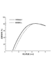
図4及び図5は、低温エリア16の温度を−15℃、高温エリア18の温度を5℃とした場合の、風速を変化させた場合の遮断効率(冷却器の負荷から換算したもの)を表したグラフである。なお、第1及び第2の送風機42,44からの風速は互いに等しく、第1の送風機42からの吐出量と下部ユニット60の吸引量とが等しくなるように設定されている。また、図4の場合、第1と第2の送風機42,44の吐出口46d,52cの幅(前後方向長さ)を100mmとし、図5の場合は、第1と第2の送風機42,44の吐出口46d,52cの幅を50mmとした。
4 and 5 show the interruption efficiency (converted from the load of the cooler) when the wind speed is changed when the temperature of the
これらのグラフから風速が約4.5m/sである場合に効率がピークとなり、3.5〜6.0m/sの範囲内において十分な効率が得られることが分かった。 From these graphs, it was found that the efficiency peaked when the wind speed was about 4.5 m / s, and sufficient efficiency was obtained in the range of 3.5 to 6.0 m / s.
また、吐出口46d,52cの幅が100mmの場合、50mmの場合よりも安定した結果が得られたが、これは100mmの場合に、より安定した空気膜が得られ、50mmではより厳しい設計が求められることを意味する。よって、吐出口46d,52cの幅は50mm以上であることが好ましい。
In addition, when the width of the
風速の大きさによって遮断効率が左右されることから、本発明者らは、更に、第1の送風機42からの空気流と第2の送風機44からの空気流とをそれぞれ別個に制御することで、よりエアカーテン効果を向上させることができると考えた。そこで、低温エリア16の冷却器の消費電力等の運転負荷を検出する検出器(負荷検出手段)(図示しない)と、各ファンユニット50,56の送風ファン48,54の回転速度検出器(風速検出手段)(図示しない)とを設け、低温エリア18の温度を維持するための冷却器の負荷が所定範囲内となるよう、送風ファン48,54の回転速度を調整して風速を制御する方法を取り入れることが有効である。また、第1の送風機42から吐出された空気量が下部ユニット60で吸引される空気量よりも多い場合、冷凍温度帯の空気の一部が高温エリフ18に流れて効率が減少し、逆に少ない場合には、冷蔵温度帯の空気の一部が下部ユニット60から低温エリア16に流入することで冷凍機の負担が増加するので、第1の送風機42から吐出された空気量と下部ユニット60で吸引される空気量とが実質的に同一となるよう送風ファン48及び吸引ファン64を制御することが好ましい。
Since the shutoff efficiency depends on the magnitude of the wind speed, the inventors further control the air flow from the
なお、ピッキング作業を行わない夜間等は、各エリア16,18の温度維持や省エネルギーの目的から、ナイトカバー、ロールカーテン等と称されるビニールシートでフローラック10の前面を覆うようにすることが好適である。
At night when picking work is not performed, the front surface of the
以上、本発明の好適な実施形態について詳細に説明したが、本発明は上記実施形態に限定されないことは言うまでもない。 As mentioned above, although preferred embodiment of this invention was described in detail, it cannot be overemphasized that this invention is not limited to the said embodiment.
例えば、エアカーテン装置における第1及び第2の送風機の吐出口に整流板を設けてもよい。 For example, you may provide a baffle plate in the discharge outlet of the 1st and 2nd air blower in an air curtain apparatus.
また、低温エリアの実質的な内部空間を可能な限り狭くし、冷却効率を向上させるために、フローラックの最下部の棚と下部ユニットの第2ダクト部との間に底板(閉じ板)を配置することも有効である。 In addition, in order to reduce the substantial internal space of the low temperature area as much as possible and improve the cooling efficiency, a bottom plate (closing plate) is provided between the lowest shelf of the flow rack and the second duct portion of the lower unit. Arranging is also effective.
更に、フローラックの各段の前部に暖簾状の遮断手段を設けることで、ピッキング時にエアカーテンを破っても、フローラック内の低温空気の高温エリアへの流出を最小限に抑制することができる(図2の符号80)。
In addition, by providing a warm shut-off means at the front of each stage of the flow rack, even if the air curtain is broken during picking, the outflow of the low temperature air in the flow rack to the high temperature area can be minimized. Yes (
10…フローラック、12…冷凍冷蔵倉庫、14…冷凍商品、16…低温エリア(冷凍温度帯のエリア)、18…高温エリア(冷蔵温度帯のエリア)、20…天井、22…仕切り壁、26R,26L…サイドフレーム、28…棚、32…商品取出し口、38…エアカーテン装置、40…上部ユニット、42…第1の送風機、44…第2の送風機、46a…第1ダクト部、46b…第2ダクト部、46d…下部開口部(第1の送風機の吐出口)、48…送風ファン、52…ダクト部、52c…下部開口部(第2の送風機の吐出口)、54…送風ファン、60…下部ユニット、62a…第1ダクト部、62b…第2ダクト部、62c…上部開口部(吸引口)、64…吸引ファン、72…集品ライン、74…コールドボックス、76…表示器、80…遮断手段。
DESCRIPTION OF
Claims (7)
前記冷凍温度帯のエリア(16)と前記冷蔵温度帯のエリア(18)との間を二層の空気流によって遮断するエアカーテン装置(38)が取り付けられており、
前記エアカーテン装置(38)が、
a.前記冷凍温度帯のエリア(16)内の空気を取り入れて吐出する第1の送風機(42)、及び、前記冷蔵温度帯のエリア(18)内の空気を取り入れて吐出すると共に、吐出口(52c)が前記第1の送風機(42)の吐出口(46dに隣接配置されている第2の送風機(44)からなる、当該ラック(10)の最上部に取り付けられる上部ユニット(40)と、
b.当該ラック(10)の最下部に配置され、前記第1の送風機(42)からの空気流を吸引して前記冷凍温度帯のエリア(16)に戻す下部ユニット(60)と、
を備えることを特徴とする、冷凍冷蔵倉庫用のラック。 In the refrigeration warehouse (12) divided into a freezing temperature zone area (16) and a refrigeration temperature zone area (18) higher than the freezing temperature zone, the freezing temperature zone area (16 In the rack (10) for storing frozen goods (14) installed in
An air curtain device (38) is installed to block between the freezing temperature zone area (16) and the refrigeration temperature zone area (18) by two layers of air flow,
The air curtain device (38)
a. The first blower (42) that takes in and discharges air in the area (16) of the refrigeration temperature zone, and takes in and discharges air in the area (18) of the refrigeration temperature zone, and discharge ports (52c) ) Is an upper unit (40) attached to the top of the rack (10), comprising a discharge port (46d) adjacent to the discharge port (46d) of the first blower (42),
b. A lower unit (60) disposed at the bottom of the rack (10), for sucking an air flow from the first blower (42) and returning it to the area (16) of the refrigeration temperature zone;
A rack for a freezer / refrigerated warehouse.
前記エアカーテン装置(38)を、
a.前記冷凍温度帯のエリア(16)内の空気を取り入れて吐出する第1の送風機(42)、及び、前記冷蔵温度帯のエリア(18)内の空気を取り入れて吐出すると共に、吐出口(52c)が前記第1の送風機(42)の吐出口(46d)に隣接配置されている第2の送風機(44)からなる、当該ラック(10)の最上部に取り付けられる上部ユニット(40)と、
b.当該ラック(10)の最下部に配置され、前記第1の送風機(42)からの空気流を吸引して前記冷凍温度帯のエリア(16)に戻す下部ユニット(60)と、
を備えるものとし、
前記第1の送風機(42)からの空気流の風速と前記第2の送風機(44)からの空気流の風速とを3.5〜6.0m/sの範囲としたことを特徴とする、エアカーテン装置の運転方法。 In the refrigeration warehouse (12) divided into a freezing temperature zone area (16) and a refrigeration temperature zone area (18) higher than the freezing temperature zone, the freezing temperature zone area (16 The air curtain device (10) is installed to block between the freezing temperature zone area (16) and the refrigeration temperature zone area (18) by a two-layer air flow. 38) In the driving method,
The air curtain device (38),
a. The first blower (42) that takes in and discharges air in the area (16) of the refrigeration temperature zone, and takes in and discharges air in the area (18) of the refrigeration temperature zone, and discharge ports (52c) An upper unit (40) attached to the top of the rack (10), comprising a second blower (44) arranged adjacent to the discharge port (46d) of the first blower (42),
b. A lower unit (60) disposed at the bottom of the rack (10), for sucking an air flow from the first blower (42) and returning it to the area (16) of the refrigeration temperature zone;
With
The wind speed of the air flow from the first blower (42) and the wind speed of the air flow from the second blower (44) are in the range of 3.5 to 6.0 m / s, Operation method of air curtain device.
前記第1の送風機(42)からの空気流の風速と前記第2の送風機(44)からの空気流の風速とを検出する風速検出手段を設け、
前記負荷検出手段から前記冷却器の運転負荷が所定範囲内にあるように、前記風速検出手段からの風速の検出値に従って前記第1の送風機(42)からの空気流の風速と前記第2の送風機(44)からの空気流の風速を制御すると共に、前記第1の送風機(42)からの空気流と同量で空気を吸引するよう前記下部ユニット(60)を制御することを特徴とする、請求項5又は6に記載のエアカーテン装置の運転方法。 A load detecting means for detecting an operating load of a cooler for cooling the area (16) in the freezing temperature zone;
A wind speed detecting means for detecting a wind speed of the air flow from the first blower (42) and a wind speed of the air flow from the second blower (44);
The wind speed of the air flow from the first blower (42) and the second speed according to the detected value of the wind speed from the wind speed detecting means so that the operation load of the cooler is within a predetermined range from the load detecting means. The air flow from the blower (44) is controlled, and the lower unit (60) is controlled to suck air in the same amount as the air flow from the first blower (42). The operation method of the air curtain apparatus of Claim 5 or 6.
Priority Applications (1)
| Application Number | Priority Date | Filing Date | Title |
|---|---|---|---|
| JP2007203459A JP4960797B2 (en) | 2007-08-03 | 2007-08-03 | Rack and air curtain device operating method for a freezer / refrigerated warehouse |
Applications Claiming Priority (1)
| Application Number | Priority Date | Filing Date | Title |
|---|---|---|---|
| JP2007203459A JP4960797B2 (en) | 2007-08-03 | 2007-08-03 | Rack and air curtain device operating method for a freezer / refrigerated warehouse |
Publications (2)
| Publication Number | Publication Date |
|---|---|
| JP2009036496A true JP2009036496A (en) | 2009-02-19 |
| JP4960797B2 JP4960797B2 (en) | 2012-06-27 |
Family
ID=40438563
Family Applications (1)
| Application Number | Title | Priority Date | Filing Date |
|---|---|---|---|
| JP2007203459A Active JP4960797B2 (en) | 2007-08-03 | 2007-08-03 | Rack and air curtain device operating method for a freezer / refrigerated warehouse |
Country Status (1)
| Country | Link |
|---|---|
| JP (1) | JP4960797B2 (en) |
Cited By (6)
| Publication number | Priority date | Publication date | Assignee | Title |
|---|---|---|---|---|
| JP2010255903A (en) * | 2009-04-23 | 2010-11-11 | Fuji Electric Retail Systems Co Ltd | Air curtain device for refrigeration storage |
| JP2010266079A (en) * | 2009-05-12 | 2010-11-25 | Fuji Electric Retail Systems Co Ltd | Freezing-refrigerating storage for picking system |
| JP2011190939A (en) * | 2010-03-11 | 2011-09-29 | Fuji Electric Co Ltd | Refrigeration warehouse |
| JP2014105893A (en) * | 2012-11-26 | 2014-06-09 | Mitsubishi Electric Corp | Air curtain device |
| CN113795176A (en) * | 2019-05-10 | 2021-12-14 | 艾若弗尔能源有限公司 | Improvement of refrigerator |
| CN116753606A (en) * | 2023-08-21 | 2023-09-15 | 佛山市南海南洋电机电器有限公司 | Control method, device, system and medium of air curtain machine |
Citations (8)
| Publication number | Priority date | Publication date | Assignee | Title |
|---|---|---|---|---|
| JPS61127385U (en) * | 1985-01-29 | 1986-08-09 | ||
| JPH0331102A (en) * | 1989-06-27 | 1991-02-08 | Ishida Syst Eng:Kk | Method and device for cold goods processing |
| JPH05264157A (en) * | 1992-03-19 | 1993-10-12 | Sanyo Electric Co Ltd | Open show case |
| JPH11211309A (en) * | 1997-07-18 | 1999-08-06 | Denso Corp | Refrigerated vehicle |
| JP2002058570A (en) * | 2000-08-22 | 2002-02-26 | Nakano Refrigerators Co Ltd | Open prefabricated refrigerator with merchandise display rack portion |
| JP2002362128A (en) * | 2001-06-11 | 2002-12-18 | Denso Corp | Vehicular air-conditioner |
| JP2003235692A (en) * | 2002-02-19 | 2003-08-26 | Sanden Corp | Walk-in open showcase |
| JP2006090619A (en) * | 2004-09-24 | 2006-04-06 | Nakano Refrigerators Co Ltd | Freezer-refrigerator for picking, and picking system for frozen-refrigerated merchandise |
-
2007
- 2007-08-03 JP JP2007203459A patent/JP4960797B2/en active Active
Patent Citations (8)
| Publication number | Priority date | Publication date | Assignee | Title |
|---|---|---|---|---|
| JPS61127385U (en) * | 1985-01-29 | 1986-08-09 | ||
| JPH0331102A (en) * | 1989-06-27 | 1991-02-08 | Ishida Syst Eng:Kk | Method and device for cold goods processing |
| JPH05264157A (en) * | 1992-03-19 | 1993-10-12 | Sanyo Electric Co Ltd | Open show case |
| JPH11211309A (en) * | 1997-07-18 | 1999-08-06 | Denso Corp | Refrigerated vehicle |
| JP2002058570A (en) * | 2000-08-22 | 2002-02-26 | Nakano Refrigerators Co Ltd | Open prefabricated refrigerator with merchandise display rack portion |
| JP2002362128A (en) * | 2001-06-11 | 2002-12-18 | Denso Corp | Vehicular air-conditioner |
| JP2003235692A (en) * | 2002-02-19 | 2003-08-26 | Sanden Corp | Walk-in open showcase |
| JP2006090619A (en) * | 2004-09-24 | 2006-04-06 | Nakano Refrigerators Co Ltd | Freezer-refrigerator for picking, and picking system for frozen-refrigerated merchandise |
Cited By (7)
| Publication number | Priority date | Publication date | Assignee | Title |
|---|---|---|---|---|
| JP2010255903A (en) * | 2009-04-23 | 2010-11-11 | Fuji Electric Retail Systems Co Ltd | Air curtain device for refrigeration storage |
| JP2010266079A (en) * | 2009-05-12 | 2010-11-25 | Fuji Electric Retail Systems Co Ltd | Freezing-refrigerating storage for picking system |
| JP2011190939A (en) * | 2010-03-11 | 2011-09-29 | Fuji Electric Co Ltd | Refrigeration warehouse |
| JP2014105893A (en) * | 2012-11-26 | 2014-06-09 | Mitsubishi Electric Corp | Air curtain device |
| CN113795176A (en) * | 2019-05-10 | 2021-12-14 | 艾若弗尔能源有限公司 | Improvement of refrigerator |
| CN116753606A (en) * | 2023-08-21 | 2023-09-15 | 佛山市南海南洋电机电器有限公司 | Control method, device, system and medium of air curtain machine |
| CN116753606B (en) * | 2023-08-21 | 2023-11-14 | 佛山市南海南洋电机电器有限公司 | Control method, device, system and medium of air curtain machine |
Also Published As
| Publication number | Publication date |
|---|---|
| JP4960797B2 (en) | 2012-06-27 |
Similar Documents
| Publication | Publication Date | Title |
|---|---|---|
| JP4960797B2 (en) | Rack and air curtain device operating method for a freezer / refrigerated warehouse | |
| CN106604664B (en) | Open refrigerated display cabinet and airflow stabilizing device | |
| EP2380465B1 (en) | Refrigerated merchandiser with air cutrains | |
| US2794325A (en) | Refrigerated display case | |
| KR20130010000A (en) | Improvements in or relating to refrigerated display appliances | |
| US6106387A (en) | Conditioned and controlled air vestibule for refrigerated warehouse | |
| GB2550360A (en) | Improvements to open display refridgerators | |
| JP4412750B2 (en) | Frozen car | |
| US6775994B1 (en) | Refrigerated display merchandiser with variable air curtain | |
| JP4270462B2 (en) | Refrigeration refrigerator for picking and picking system for refrigerated goods | |
| US4299099A (en) | Open front refrigeration system | |
| US20050097910A1 (en) | Open showcase | |
| JP5383748B2 (en) | Showcase | |
| JP2009097782A (en) | Freezing refrigerating warehouse | |
| JP2007222438A (en) | Showcase, temperature maintaining case and temperature detection method for temperature maintaining case | |
| JP4388346B2 (en) | Open showcase | |
| JP3676309B2 (en) | Walk-in open showcase | |
| JP5625402B2 (en) | Refrigerated warehouse | |
| CN210663509U (en) | Ventilation device for refrigeration equipment and refrigeration equipment | |
| JP2012117799A (en) | Freezer-refrigerator | |
| JPH06180171A (en) | Refrigerator show case | |
| US9675186B2 (en) | Merchandiser including venting frame for top containers | |
| JP5257165B2 (en) | Refrigeration equipment | |
| JP2010249346A (en) | Showcase | |
| KR200210103Y1 (en) | Showcase with refrigeration means |
Legal Events
| Date | Code | Title | Description |
|---|---|---|---|
| A621 | Written request for application examination |
Free format text: JAPANESE INTERMEDIATE CODE: A621 Effective date: 20100621 |
|
| A977 | Report on retrieval |
Free format text: JAPANESE INTERMEDIATE CODE: A971007 Effective date: 20120224 |
|
| TRDD | Decision of grant or rejection written | ||
| A01 | Written decision to grant a patent or to grant a registration (utility model) |
Free format text: JAPANESE INTERMEDIATE CODE: A01 Effective date: 20120313 |
|
| A01 | Written decision to grant a patent or to grant a registration (utility model) |
Free format text: JAPANESE INTERMEDIATE CODE: A01 |
|
| A61 | First payment of annual fees (during grant procedure) |
Free format text: JAPANESE INTERMEDIATE CODE: A61 Effective date: 20120323 |
|
| FPAY | Renewal fee payment (event date is renewal date of database) |
Free format text: PAYMENT UNTIL: 20150330 Year of fee payment: 3 |
|
| R150 | Certificate of patent or registration of utility model |
Ref document number: 4960797 Country of ref document: JP Free format text: JAPANESE INTERMEDIATE CODE: R150 Free format text: JAPANESE INTERMEDIATE CODE: R150 |
|
| R250 | Receipt of annual fees |
Free format text: JAPANESE INTERMEDIATE CODE: R250 |
|
| R250 | Receipt of annual fees |
Free format text: JAPANESE INTERMEDIATE CODE: R250 |
|
| S111 | Request for change of ownership or part of ownership |
Free format text: JAPANESE INTERMEDIATE CODE: R313117 |
|
| R250 | Receipt of annual fees |
Free format text: JAPANESE INTERMEDIATE CODE: R250 |
|
| R350 | Written notification of registration of transfer |
Free format text: JAPANESE INTERMEDIATE CODE: R350 |
|
| R250 | Receipt of annual fees |
Free format text: JAPANESE INTERMEDIATE CODE: R250 |
|
| R250 | Receipt of annual fees |
Free format text: JAPANESE INTERMEDIATE CODE: R250 |
|
| R250 | Receipt of annual fees |
Free format text: JAPANESE INTERMEDIATE CODE: R250 |
|
| R250 | Receipt of annual fees |
Free format text: JAPANESE INTERMEDIATE CODE: R250 |
|
| R250 | Receipt of annual fees |
Free format text: JAPANESE INTERMEDIATE CODE: R250 |
|
| R250 | Receipt of annual fees |
Free format text: JAPANESE INTERMEDIATE CODE: R250 |