EP1327416A2 - Vorrichtung zur Ultraschallsonographie - Google Patents
Vorrichtung zur Ultraschallsonographie Download PDFInfo
- Publication number
- EP1327416A2 EP1327416A2 EP03000822A EP03000822A EP1327416A2 EP 1327416 A2 EP1327416 A2 EP 1327416A2 EP 03000822 A EP03000822 A EP 03000822A EP 03000822 A EP03000822 A EP 03000822A EP 1327416 A2 EP1327416 A2 EP 1327416A2
- Authority
- EP
- European Patent Office
- Prior art keywords
- unit
- digital
- signal
- mixer
- ultrasound
- Prior art date
- Legal status (The legal status is an assumption and is not a legal conclusion. Google has not performed a legal analysis and makes no representation as to the accuracy of the status listed.)
- Granted
Links
Images
Classifications
-
- A—HUMAN NECESSITIES
- A61—MEDICAL OR VETERINARY SCIENCE; HYGIENE
- A61B—DIAGNOSIS; SURGERY; IDENTIFICATION
- A61B8/00—Diagnosis using ultrasonic, sonic or infrasonic waves
- A61B8/06—Measuring blood flow
-
- A—HUMAN NECESSITIES
- A61—MEDICAL OR VETERINARY SCIENCE; HYGIENE
- A61B—DIAGNOSIS; SURGERY; IDENTIFICATION
- A61B8/00—Diagnosis using ultrasonic, sonic or infrasonic waves
- A61B8/08—Detecting organic movements or changes, e.g. tumours, cysts, swellings
- A61B8/0808—Detecting organic movements or changes, e.g. tumours, cysts, swellings for diagnosis of the brain
- A61B8/0816—Detecting organic movements or changes, e.g. tumours, cysts, swellings for diagnosis of the brain using echo-encephalography
-
- A—HUMAN NECESSITIES
- A61—MEDICAL OR VETERINARY SCIENCE; HYGIENE
- A61N—ELECTROTHERAPY; MAGNETOTHERAPY; RADIATION THERAPY; ULTRASOUND THERAPY
- A61N7/00—Ultrasound therapy
Definitions
- the present invention relates to a device for diagnostic or therapeutic ultrasound according to the preamble of the main claim.
- Such a device is from the prior art, for example by products of the applicant, generally known and is typically used for intracranial vascular observation and diagnostics, for example in the skull of a patient.
- a suitable ultrasound probe is used for this purpose, typical operating frequencies are in the range between 2 and 2.5 MHz, attached to the patient's head, and an ultrasonic unit generates a suitable transmit signal for the probe.
- the one also recorded by the probe Receive signal is then an analog mixer unit fed, mixed with the carrier signal, and the Doppler signal the mixed product is then by means of low-pass filtering separated and sent for further processing.
- this Doppler signal then becomes a visual one Representation for an on the screen of an evaluation unit generated which it the operator of such Device enables movements (e.g. blood flow in the Vessels) to be recorded and assessed.
- the basic application can then be used for numerous other diagnostics and other evaluations, such as the additional detection of those occurring in a blood flow Embolism or simultaneous multi-channel display of one Majority of observation depths.
- each of these known ultrasonic devices has the principle problem that the mixers used to generate the Doppler signal as a low frequency Useful signal over an entire, desired amplitude and frequency response work linearly; just add Noise components that can cause interference in border areas.
- the object of the present invention is therefore a generic Device for diganostic or therapeutic Ultrasound sonography, especially for transcranial ones Vascular diagnostics, with regard to the linearity of the To optimize amplitude and frequency response, noise too reduce, and in addition, the device easier and more efficient and with less adjustment and adjustment effort to be able to manufacture.
- the use provides an advantage in accordance with the invention one directly on the receiving side by means of an AD converter digital mixer coupled to the probe for
- digital are the operating limits as well as the noise by the resolution of the digital signal (or its signal frequency / bit rate) determined and therefore depend on the ability to conduct and the computing capacity of the downstream digital signal processing electronics.
- the digital mixer consists of a binary Multiplier within its resolution (bit width) is completely linear, and its bandwidth is only from depends on the sampling rate of the signals to be mixed.
- the mixing frequency (sine / cosine component) is determined by a digital frequency generator generated as a pulse generator, for this there is a memory with sine / cosine table values has shown to be particularly preferred, which is then read out by means of a counter unit.
- Sampling rate is a typical one at the receiving end of the analog-to-digital converter generated input signal in the order of magnitude of 12 MHz, whereby, according to the digital mix, with With the help of digital low-pass filters, this data rate is multi-stage and gradually to an order of magnitude between 1 and 2 MHz is reduced (corresponds to a frequency of 1.5 MHz a resolution of approx. 1 mm, based on the Speed of sound in water).
- the present invention is advantageous achieved that optimized or preset Noise characteristics combined with perfect linearity and, because by computer-controlled adjustable mixer and transmission frequency as well as configuration of the filters practically any adjustability to desired Depths is possible by the device according to the invention an unimagined flexibility in use with the least possible adjustment and manual configuration effort reached.
- the advantage that the number the depths to be displayed (in the end, yes, continuously contained in the digital Doppler signal) only by the existing computing power is limited, so here too remarkable with the lowest hardware and manufacturing effort Advantages can be realized.
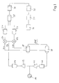
- Fig. 1 is a schematic block diagram of the invention Device for analytical or therapeutic ultrasound ultrasound according to a preferred embodiment.
- the output signal in an otherwise known manner on Head of a patient attached ultrasound probe 10 is via a preamplifier 12 on the receiving side of an analog-digital converter unit 14 supplied, which the amplified received signal fast and with high resolution (typical signal frequency digitized at the output of the AD converter 14: 12 MHz) and feeds a digital mixer 16 which, separated for a sine component and a cosine component, the digital input signal with the sine component or Cosine component one of a signal generator 18 on the generated the carrier frequency corresponding to the probe frequency Mixer signal mixes.
- a preamplifier 12 on the receiving side of an analog-digital converter unit 14 supplied, which the amplified received signal fast and with high resolution (typical signal frequency digitized at the output of the AD converter 14: 12 MHz) and feeds a digital mixer 16 which, separated for a sine component and a cosine component, the digital input signal with the sine component or Cosine component one of a signal generator 18 on the generated the carrier frequency corresponding to the probe frequency Mixer signal mixes.
- the digital mixer 16 with the help assigned by the sine or cosine branch digital multipliers 20, 22 the digital multiplication product of the digitized received signal (from the Unit 14) and the sine or cosine component of the of the carrier frequency signal generated by the unit 18, so that, in the known way, at the output of the multiplier 20, 22 the Doppler mixing frequencies are formed, wherein then downstream digital filter units 24, 26, acting as a low pass, the desired, the Doppler shift corresponding signal (corresponding to the difference of input signal and mixer frequency).
- these filters are FIR filters that reduce the data rate realized and bring about a reduction in the data rate of 1: 2, so that a downstream digital multiplexer unit 28 two 6 MHz data streams flow to it.
- the multiplexer unit 28 generates a 6 from these signals MHz output signal, which is then in a downstream digital low-pass filter stage 30 again in the data rate is reduced by 1: 4, so that a downstream sample storage unit 32 as a signal processing unit in Digital signals with a data rate of approx. 1.5 MHz are present.
- a resolution of approximately one millimeter (based on the speed of sound in water) are typical, via a connected host computer (not shown) adjustable depths of the ultrasonic measurement between 20 and 150 mm, whereby, as described, the one used digital mixer technology for complete linearity along this area. It is particularly preferred suitably preselected or preset depths by appropriate Control of this sample storage unit as Read values directly and a separate processing, about the M-mode display.
- the total data stream also enters a downstream one FIFO buffer memory 34 and from this into a computer interface 36 which, e.g. as a PCI interface, the connection to commercially available PC computing infrastructure manufactures and the complete signal processing and representation of the Doppler signal in otherwise known Way.
- a computer interface 36 which, e.g. as a PCI interface, the connection to commercially available PC computing infrastructure manufactures and the complete signal processing and representation of the Doppler signal in otherwise known Way.
- the digital signal generator 18 also ensures the PRF signal for a downstream waveform shaping unit 38 to provide for control, the Output signal of this unit (so-called burst signal) then via a digital-to-analog converter unit 40 and one downstream power amplifier 42 to the ultrasound probe 10 is created.
- the digital one realized with the unit 38 Signal shaping is programmable and, like that Signal preprocessing on the receiving side as above described, suitable by the connected host computer unit program-controlled.
- Units 18 and 38 also receive a suitably chosen reference frequency fref (e.g. 48 MHz).
- the digital becomes concrete Mixer electronics (i.e. units 20, 22) including pulse generator 18 and digital signal former 38 as a digital module integrated and typically lies as suitably configured Chip before, so that, along with suitable by the Computer implemented filter units or the multiplexer and the sample storage unit, the invention Device is easy to implement in terms of manufacturing technology and practically no manual calibration or adjustment effort requires.
- concrete Mixer electronics i.e. units 20, 22
- pulse generator 18 and digital signal former 38 as a digital module integrated and typically lies as suitably configured Chip before, so that, along with suitable by the Computer implemented filter units or the multiplexer and the sample storage unit, the invention Device is easy to implement in terms of manufacturing technology and practically no manual calibration or adjustment effort requires.
- Doppler demodulation in a simple and flexible manner realize which, in deviation from the so far exclusively analog technology used in diagnostics in an unprecedented way linearity along the entire usable amplitude and frequency range with only from the digital resolution of certain low noise levels combined.
Abstract
Description
Claims (12)
- Vorrichtung zur diagnostischen oder therapeutischen Ultraschallsonographie mit
einer zum Verbinden mit einer Ultraschallsonde (10) zum Erzeugen von Ultraschallsignalen sowie zum Empfangen reflektierter Ultraschallsignale ausgebildeten Ultraschalleinheit,
die einen Impulsgenerator (18) für die sendeseitig erzeugten periodischen Ultraschallsignale sowie empfangsseitig eine Mischereinheit (16) und eine Filtereinheit (24,26,30) aufweist und zum Verbinden mit einer Signalauswerteeinheit (PC) zum Aufbereiten und visuellen Darstellen von aus den reflektierten Ultraschallsignalen erzeugten Daten eingerichtet ist,
dadurch gekennzeichnet, dass
der Ultraschallsonde empfangsseitig eine Analog-Digital-Wandlereinheit (14) nachgeschaltet ist, deren digitales Ausgangssignal in der als digitaler Mischer ausgebildeten Mischereinheit (16,20,22) mit einem Mischersignal des Impulsgenerators (18) digital gemischt werden kann. - Vorrichtung nach Anspruch 1, dadurch gekennzeichnet, dass dem digitalen Mischer eine digitale, als Tiefpaßfilter wirkende Filtereinheit (24,26), insbesondere FIR-Filter, nachgeschaltet ist.
- Vorrichtung nach Anspruch 1 oder 2, dadurch gekennzeichnet, dass die Ultraschalleinheit empfangsseitig so ausgebildet ist, dass ein einem Sinus-Mischersignal entsprechender Ausgangszweig und ein einem Cosinus-Mischersignal entsprechender Ausgangszweig mit einer digitalen Multiplexereinheit (28) zum Erzeugen eines gemultiplexten digitalen Dopplersignals verbunden ist.
- Vorrichtung nach Anspruch 3, dadurch gekennzeichnet, dass zwischen dem digitalen Mischer (16) und der digitalen Multiplexereinheit (28)in jedem Ausgangszweig ein digitales Tiefpaßfilter (24,26)vorgesehen ist.
- Vorrichtung nach Anspruch 2 oder 3, dadurch gekennzeichnet, dass der Multiplexereinheit eine als Tiefpaßfilter wirkende Filtereinheit (30), insbesondere FIR-Filter, nachgeschaltet ist.
- Vorrichtung nach einem der Ansprüche 3 bis 5, dadurch gekennzeichnet, dass der Multiplexereinheit eine Signalaufbereitungseinheit (32) nachgeschaltet ist, die der Signalauswerteeinheit vorgeschaltet und so ausgebildet ist, dass sie aus einem Datenstrom der Multiplexereinheit eine vorbestimmte, der gewünschten Beobachtungstiefe entsprechende Datenkomponente abtrennt und der Signalauswerteeinheit zuleitet.
- Vorrichtung nach Anspruch 6, dadurch gekennzeichnet, dass die Signalauswerteeinheit und/oder die Signalaufbereitungseinheit so ausgebildet sind, dass sie aus den abgetrennten Datenkomponenten eine einem M-Mode entsprechende Bilddarstellung auf einem Bildschirm oder dergleichen Bildausgabeeinheit der Signalauswerteeinheit erzeugen.
- Vorrichtung nach einem der Ansprüche 1 bis 7, dadurch gekennzeichnet, dass der Impulsgenerator (18) als digitaler Frequenzgenerator ausgebildet ist, der, insbesondere mittels einer zugeordneten digitalen Tabelleneinheit, ein Mischersignal mit Sinus- und Cosinusanteil für den digiten Mischer (16,20,22) bereitstellt und sendeseitig einen digitalen Impulsformer (38) zur Erzeugung des Sendesignals ansteuert.
- Vorrichtung nach einem der Ansprüche 1 bis 8, dadurch gekennzeichnet, dass der digitale Mischer (16), der Impulsgenerator (18) sowie ein sendeseitig vorgesehener, dem Impulsgenerator nachgeschalteter Impulsformer (38) als integriertes Halbleiterbauelement realisiert und bevorzugt programmtechnisch einstell- oder beeinflußbar sind.
- Vorrichtung nach einem der Ansprüche 1 bis 9, gekennzeichnet durch eine Betriebsfrequenz der Ultraschallsonde im Bereich zwischen 1,5 und 12 MHz, insbesondere zwischen 2 und 8 MHz, wobei ein dem digitalen Mischer empfangsseitig zugeleiteter digitaler Datenstrom aus der Analog-Digital-Wandlereinheit (14) eine Frequenz im Bereich zwischen 10 und 15 MHz aufweist.
- Vorrichtung nach Anspruch 10, dadurch gekennzeichnet, dass eine der Signalauswerteeinheit zugeleitete Signalfrequenz des tiefpaßgefilterten und gemultiplexten Mischerausgangssignals als Dopplersignal im Bereich zwischen 1 und 2 MHz liegt.
- Verwendung der Vorrichtung nach einem der Ansprüche 1 bis 11 als Vorrichtung zur intrakraniellen Gefäßbeobachtung und -diagnostik.
Applications Claiming Priority (2)
| Application Number | Priority Date | Filing Date | Title |
|---|---|---|---|
| DE20200617U DE20200617U1 (de) | 2002-01-15 | 2002-01-15 | Vorrichtung zur diagnostischen oder therapeutischen Ultraschallsonographie |
| DE20200617U | 2002-01-15 |
Publications (3)
| Publication Number | Publication Date |
|---|---|
| EP1327416A2 true EP1327416A2 (de) | 2003-07-16 |
| EP1327416A3 EP1327416A3 (de) | 2005-03-30 |
| EP1327416B1 EP1327416B1 (de) | 2007-06-13 |
Family
ID=7966626
Family Applications (1)
| Application Number | Title | Priority Date | Filing Date |
|---|---|---|---|
| EP03000822A Expired - Lifetime EP1327416B1 (de) | 2002-01-15 | 2003-01-15 | Vorrichtung zur Ultraschallsonographie |
Country Status (3)
| Country | Link |
|---|---|
| EP (1) | EP1327416B1 (de) |
| AT (1) | ATE364352T1 (de) |
| DE (3) | DE20200617U1 (de) |
Families Citing this family (1)
| Publication number | Priority date | Publication date | Assignee | Title |
|---|---|---|---|---|
| WO2004103184A2 (en) * | 2003-05-21 | 2004-12-02 | Borders Nhs Board | Method for diagnosis and treatment of vessel occlusion |
Citations (5)
| Publication number | Priority date | Publication date | Assignee | Title |
|---|---|---|---|---|
| US4975885A (en) * | 1988-09-30 | 1990-12-04 | Siemens Aktiengesellschaft | Digital input stage for an ultrasound apparatus |
| US5437281A (en) * | 1992-01-14 | 1995-08-01 | Diasonics Ultrasound, Inc. | Direct demodulation in ultrasound instruments |
| US5515727A (en) * | 1992-09-22 | 1996-05-14 | Hitachi Medical Corporation | Ultrasound signal processor |
| DE19716810A1 (de) * | 1997-04-22 | 1998-11-05 | Dwl Elektron Systeme Gmbh | Vorrichtung und Verfahren zum Erfassen von an einem Fluidstrom reflektierten Ultraschall-Signalen |
| US6248071B1 (en) * | 2000-01-28 | 2001-06-19 | U-Systems, Inc. | Demodulating wide-band ultrasound signals |
-
2002
- 2002-01-15 DE DE20200617U patent/DE20200617U1/de not_active Expired - Lifetime
-
2003
- 2003-01-15 DE DE50307441T patent/DE50307441D1/de not_active Expired - Lifetime
- 2003-01-15 DE DE10301337A patent/DE10301337A1/de not_active Withdrawn
- 2003-01-15 AT AT03000822T patent/ATE364352T1/de not_active IP Right Cessation
- 2003-01-15 EP EP03000822A patent/EP1327416B1/de not_active Expired - Lifetime
Patent Citations (5)
| Publication number | Priority date | Publication date | Assignee | Title |
|---|---|---|---|---|
| US4975885A (en) * | 1988-09-30 | 1990-12-04 | Siemens Aktiengesellschaft | Digital input stage for an ultrasound apparatus |
| US5437281A (en) * | 1992-01-14 | 1995-08-01 | Diasonics Ultrasound, Inc. | Direct demodulation in ultrasound instruments |
| US5515727A (en) * | 1992-09-22 | 1996-05-14 | Hitachi Medical Corporation | Ultrasound signal processor |
| DE19716810A1 (de) * | 1997-04-22 | 1998-11-05 | Dwl Elektron Systeme Gmbh | Vorrichtung und Verfahren zum Erfassen von an einem Fluidstrom reflektierten Ultraschall-Signalen |
| US6248071B1 (en) * | 2000-01-28 | 2001-06-19 | U-Systems, Inc. | Demodulating wide-band ultrasound signals |
Also Published As
| Publication number | Publication date |
|---|---|
| EP1327416B1 (de) | 2007-06-13 |
| DE10301337A1 (de) | 2003-09-18 |
| DE50307441D1 (de) | 2007-07-26 |
| EP1327416A3 (de) | 2005-03-30 |
| ATE364352T1 (de) | 2007-07-15 |
| DE20200617U1 (de) | 2002-06-13 |
Similar Documents
| Publication | Publication Date | Title |
|---|---|---|
| DE3829999C2 (de) | ||
| DE3827513C2 (de) | ||
| DE2811544C3 (de) | Ultraschallsender/Empfänger | |
| DE3734571C2 (de) | Ultraschall-Diagnosevorrichtung | |
| DE3702355C2 (de) | ||
| DE3241670C2 (de) | Vorrichtung und Verfahren zur Ermittlung der Blutströmungsgeschwindigkeit und zur Darstellung biologischer Gewebestrukturen | |
| DE2645738A1 (de) | Ultraschallstrahlabtastung | |
| DE10039346B4 (de) | Verfahren und Vorrichtung zur dynamischen Rauschverringerung für ein Doppler-Audioausgangssignal | |
| EP0204192B1 (de) | Schaltungsanordnung zum Erfassen der Herzschlagsbewegung | |
| EP1795890A1 (de) | Verfahren und Vorrichtung zur Ultraschalldetektion von Diskontinuitäten in einem Materialbereich | |
| DE2848467C3 (de) | Ultraschall-Diagnosegerät | |
| DE112010003150T5 (de) | Ultrasonografievorrichtung | |
| DE102018124816A1 (de) | Radarzielsimulator und Verfahren zur Radarzielsimulation | |
| DE19526210C2 (de) | Medizinisches Doppler-Ultraschallgerät | |
| EP1474708A1 (de) | Ortungsgerät und zugehöriges verfahren | |
| DE69839062T2 (de) | Vorrichtung zur ultraschall-diagnose | |
| DE19733091B4 (de) | Vorrichtung und Verfahren zur Emboliedetektion | |
| DE3121781A1 (de) | Verfahren und vorrichtung zur hoehenstandsmessung eines stroemenden gutes oder materials | |
| DE2843985C3 (de) | Ultraschall-Diagnosegerät | |
| EP1327416B1 (de) | Vorrichtung zur Ultraschallsonographie | |
| DE1473699A1 (de) | Auf Grundlage der Fortpflanzung von Schallwellen in den zu untersuchenden Medien arbeitende Messvorrichtung | |
| DE19757466A1 (de) | Verfahren und Einrichtung zum Verhindern eines axialen räumlichen Alias-Effektes in einer Ultraschall-Bildgebungs-Einrichtung mit Komplexsignaldetektor | |
| DE19521197A1 (de) | Anordnung und Verfahren zum gleichzeitigen Echtzeit-Ultraschall-Abbilden von biologischen Geweben und zum Messen der Geschwindigkeit des Blutstromes | |
| DE1812017C3 (de) | Anordnung zur Messung der Innenabmessung von Gelassen im lebenden Korper | |
| DE19716810B4 (de) | Vorrichtung und Verfahren zum Erfassen von an einem Fluidstrom reflektierten Ultraschall-Signalen |
Legal Events
| Date | Code | Title | Description |
|---|---|---|---|
| PUAI | Public reference made under article 153(3) epc to a published international application that has entered the european phase |
Free format text: ORIGINAL CODE: 0009012 |
|
| AK | Designated contracting states |
Designated state(s): AT BE BG CH CY CZ DE DK EE ES FI FR GB GR HU IE IT LI LU MC NL PT SE SI SK TR |
|
| AX | Request for extension of the european patent |
Extension state: AL LT LV MK RO |
|
| PUAL | Search report despatched |
Free format text: ORIGINAL CODE: 0009013 |
|
| AK | Designated contracting states |
Kind code of ref document: A3 Designated state(s): AT BE BG CH CY CZ DE DK EE ES FI FR GB GR HU IE IT LI LU MC NL PT SE SI SK TR |
|
| AX | Request for extension of the european patent |
Extension state: AL LT LV MK RO |
|
| 17P | Request for examination filed |
Effective date: 20050922 |
|
| AKX | Designation fees paid |
Designated state(s): AT BE BG CH CY CZ DE DK EE ES FI FR GB GR HU IE IT LI LU MC NL PT SE SI SK TR |
|
| RAP1 | Party data changed (applicant data changed or rights of an application transferred) |
Owner name: COMPUMEDICS GERMANY GMBH |
|
| GRAP | Despatch of communication of intention to grant a patent |
Free format text: ORIGINAL CODE: EPIDOSNIGR1 |
|
| GRAS | Grant fee paid |
Free format text: ORIGINAL CODE: EPIDOSNIGR3 |
|
| GRAA | (expected) grant |
Free format text: ORIGINAL CODE: 0009210 |
|
| AK | Designated contracting states |
Kind code of ref document: B1 Designated state(s): AT BE BG CH CY CZ DE DK EE ES FI FR GB GR HU IE IT LI LU MC NL PT SE SI SK TR |
|
| REG | Reference to a national code |
Ref country code: GB Ref legal event code: FG4D Free format text: NOT ENGLISH |
|
| REG | Reference to a national code |
Ref country code: CH Ref legal event code: EP |
|
| REG | Reference to a national code |
Ref country code: IE Ref legal event code: FG4D Free format text: LANGUAGE OF EP DOCUMENT: GERMAN |
|
| REF | Corresponds to: |
Ref document number: 50307441 Country of ref document: DE Date of ref document: 20070726 Kind code of ref document: P |
|
| PG25 | Lapsed in a contracting state [announced via postgrant information from national office to epo] |
Ref country code: SE Free format text: LAPSE BECAUSE OF FAILURE TO SUBMIT A TRANSLATION OF THE DESCRIPTION OR TO PAY THE FEE WITHIN THE PRESCRIBED TIME-LIMIT Effective date: 20070913 |
|
| GBT | Gb: translation of ep patent filed (gb section 77(6)(a)/1977) |
Effective date: 20070829 |
|
| REG | Reference to a national code |
Ref country code: CH Ref legal event code: NV Representative=s name: HIEBSCH & PEEGE AG PATENTANWAELTE |
|
| NLV1 | Nl: lapsed or annulled due to failure to fulfill the requirements of art. 29p and 29m of the patents act | ||
| REG | Reference to a national code |
Ref country code: IE Ref legal event code: FD4D |
|
| PG25 | Lapsed in a contracting state [announced via postgrant information from national office to epo] |
Ref country code: BG Free format text: LAPSE BECAUSE OF FAILURE TO SUBMIT A TRANSLATION OF THE DESCRIPTION OR TO PAY THE FEE WITHIN THE PRESCRIBED TIME-LIMIT Effective date: 20070913 Ref country code: SI Free format text: LAPSE BECAUSE OF FAILURE TO SUBMIT A TRANSLATION OF THE DESCRIPTION OR TO PAY THE FEE WITHIN THE PRESCRIBED TIME-LIMIT Effective date: 20070613 Ref country code: NL Free format text: LAPSE BECAUSE OF FAILURE TO SUBMIT A TRANSLATION OF THE DESCRIPTION OR TO PAY THE FEE WITHIN THE PRESCRIBED TIME-LIMIT Effective date: 20070613 Ref country code: IE Free format text: LAPSE BECAUSE OF FAILURE TO SUBMIT A TRANSLATION OF THE DESCRIPTION OR TO PAY THE FEE WITHIN THE PRESCRIBED TIME-LIMIT Effective date: 20070613 Ref country code: ES Free format text: LAPSE BECAUSE OF FAILURE TO SUBMIT A TRANSLATION OF THE DESCRIPTION OR TO PAY THE FEE WITHIN THE PRESCRIBED TIME-LIMIT Effective date: 20070924 Ref country code: CZ Free format text: LAPSE BECAUSE OF FAILURE TO SUBMIT A TRANSLATION OF THE DESCRIPTION OR TO PAY THE FEE WITHIN THE PRESCRIBED TIME-LIMIT Effective date: 20070613 Ref country code: PT Free format text: LAPSE BECAUSE OF FAILURE TO SUBMIT A TRANSLATION OF THE DESCRIPTION OR TO PAY THE FEE WITHIN THE PRESCRIBED TIME-LIMIT Effective date: 20071113 |
|
| REG | Reference to a national code |
Ref country code: CH Ref legal event code: PFA Owner name: COMPUMEDICS GERMANY GMBH Free format text: COMPUMEDICS GERMANY GMBH#JOSEF-SCHUETTLER-STRASSE 2#78224 SINGEN (DE) -TRANSFER TO- COMPUMEDICS GERMANY GMBH#JOSEF-SCHUETTLER-STRASSE 2#78224 SINGEN (DE) |
|
| EN | Fr: translation not filed | ||
| PG25 | Lapsed in a contracting state [announced via postgrant information from national office to epo] |
Ref country code: SK Free format text: LAPSE BECAUSE OF FAILURE TO SUBMIT A TRANSLATION OF THE DESCRIPTION OR TO PAY THE FEE WITHIN THE PRESCRIBED TIME-LIMIT Effective date: 20070613 |
|
| PLBE | No opposition filed within time limit |
Free format text: ORIGINAL CODE: 0009261 |
|
| STAA | Information on the status of an ep patent application or granted ep patent |
Free format text: STATUS: NO OPPOSITION FILED WITHIN TIME LIMIT |
|
| PG25 | Lapsed in a contracting state [announced via postgrant information from national office to epo] |
Ref country code: IT Free format text: LAPSE BECAUSE OF FAILURE TO SUBMIT A TRANSLATION OF THE DESCRIPTION OR TO PAY THE FEE WITHIN THE PRESCRIBED TIME-LIMIT Effective date: 20070613 Ref country code: DK Free format text: LAPSE BECAUSE OF FAILURE TO SUBMIT A TRANSLATION OF THE DESCRIPTION OR TO PAY THE FEE WITHIN THE PRESCRIBED TIME-LIMIT Effective date: 20070613 Ref country code: GR Free format text: LAPSE BECAUSE OF FAILURE TO SUBMIT A TRANSLATION OF THE DESCRIPTION OR TO PAY THE FEE WITHIN THE PRESCRIBED TIME-LIMIT Effective date: 20070914 |
|
| 26N | No opposition filed |
Effective date: 20080314 |
|
| BERE | Be: lapsed |
Owner name: COMPUMEDICS GERMANY G.M.B.H. Effective date: 20080131 |
|
| PG25 | Lapsed in a contracting state [announced via postgrant information from national office to epo] |
Ref country code: FR Free format text: LAPSE BECAUSE OF FAILURE TO SUBMIT A TRANSLATION OF THE DESCRIPTION OR TO PAY THE FEE WITHIN THE PRESCRIBED TIME-LIMIT Effective date: 20080208 |
|
| PG25 | Lapsed in a contracting state [announced via postgrant information from national office to epo] |
Ref country code: MC Free format text: LAPSE BECAUSE OF NON-PAYMENT OF DUE FEES Effective date: 20080131 |
|
| PG25 | Lapsed in a contracting state [announced via postgrant information from national office to epo] |
Ref country code: EE Free format text: LAPSE BECAUSE OF FAILURE TO SUBMIT A TRANSLATION OF THE DESCRIPTION OR TO PAY THE FEE WITHIN THE PRESCRIBED TIME-LIMIT Effective date: 20070613 |
|
| PG25 | Lapsed in a contracting state [announced via postgrant information from national office to epo] |
Ref country code: FI Free format text: LAPSE BECAUSE OF FAILURE TO SUBMIT A TRANSLATION OF THE DESCRIPTION OR TO PAY THE FEE WITHIN THE PRESCRIBED TIME-LIMIT Effective date: 20070613 Ref country code: BE Free format text: LAPSE BECAUSE OF NON-PAYMENT OF DUE FEES Effective date: 20080131 |
|
| PG25 | Lapsed in a contracting state [announced via postgrant information from national office to epo] |
Ref country code: AT Free format text: LAPSE BECAUSE OF NON-PAYMENT OF DUE FEES Effective date: 20080115 |
|
| PG25 | Lapsed in a contracting state [announced via postgrant information from national office to epo] |
Ref country code: CY Free format text: LAPSE BECAUSE OF FAILURE TO SUBMIT A TRANSLATION OF THE DESCRIPTION OR TO PAY THE FEE WITHIN THE PRESCRIBED TIME-LIMIT Effective date: 20070613 |
|
| PG25 | Lapsed in a contracting state [announced via postgrant information from national office to epo] |
Ref country code: HU Free format text: LAPSE BECAUSE OF FAILURE TO SUBMIT A TRANSLATION OF THE DESCRIPTION OR TO PAY THE FEE WITHIN THE PRESCRIBED TIME-LIMIT Effective date: 20071214 Ref country code: LU Free format text: LAPSE BECAUSE OF NON-PAYMENT OF DUE FEES Effective date: 20080115 |
|
| PG25 | Lapsed in a contracting state [announced via postgrant information from national office to epo] |
Ref country code: TR Free format text: LAPSE BECAUSE OF FAILURE TO SUBMIT A TRANSLATION OF THE DESCRIPTION OR TO PAY THE FEE WITHIN THE PRESCRIBED TIME-LIMIT Effective date: 20070613 |
|
| PGFP | Annual fee paid to national office [announced via postgrant information from national office to epo] |
Ref country code: GB Payment date: 20180306 Year of fee payment: 16 Ref country code: CH Payment date: 20180306 Year of fee payment: 16 |
|
| PGFP | Annual fee paid to national office [announced via postgrant information from national office to epo] |
Ref country code: DE Payment date: 20190131 Year of fee payment: 17 |
|
| REG | Reference to a national code |
Ref country code: CH Ref legal event code: PL |
|
| GBPC | Gb: european patent ceased through non-payment of renewal fee |
Effective date: 20190115 |
|
| PG25 | Lapsed in a contracting state [announced via postgrant information from national office to epo] |
Ref country code: GB Free format text: LAPSE BECAUSE OF NON-PAYMENT OF DUE FEES Effective date: 20190115 Ref country code: CH Free format text: LAPSE BECAUSE OF NON-PAYMENT OF DUE FEES Effective date: 20190131 Ref country code: LI Free format text: LAPSE BECAUSE OF NON-PAYMENT OF DUE FEES Effective date: 20190131 |
|
| REG | Reference to a national code |
Ref country code: DE Ref legal event code: R119 Ref document number: 50307441 Country of ref document: DE |
|
| PG25 | Lapsed in a contracting state [announced via postgrant information from national office to epo] |
Ref country code: DE Free format text: LAPSE BECAUSE OF NON-PAYMENT OF DUE FEES Effective date: 20200801 |