EP1327250B1 - Verfahren zum zusammensetzen eines druckwasserreaktor-kernes und entsprechender druckwasserreaktorkern - Google Patents
Verfahren zum zusammensetzen eines druckwasserreaktor-kernes und entsprechender druckwasserreaktorkern Download PDFInfo
- Publication number
- EP1327250B1 EP1327250B1 EP02738040A EP02738040A EP1327250B1 EP 1327250 B1 EP1327250 B1 EP 1327250B1 EP 02738040 A EP02738040 A EP 02738040A EP 02738040 A EP02738040 A EP 02738040A EP 1327250 B1 EP1327250 B1 EP 1327250B1
- Authority
- EP
- European Patent Office
- Prior art keywords
- core
- fuel
- edge
- bent
- fuel elements
- Prior art date
- Legal status (The legal status is an assumption and is not a legal conclusion. Google has not performed a legal analysis and makes no representation as to the accuracy of the status listed.)
- Expired - Lifetime
Links
- XLYOFNOQVPJJNP-UHFFFAOYSA-N water Substances O XLYOFNOQVPJJNP-UHFFFAOYSA-N 0.000 title claims description 9
- 238000000034 method Methods 0.000 title claims description 8
- 239000000446 fuel Substances 0.000 claims description 156
- 238000005452 bending Methods 0.000 claims description 9
- 230000008569 process Effects 0.000 claims description 2
- 230000009257 reactivity Effects 0.000 claims description 2
- 238000000429 assembly Methods 0.000 description 34
- 230000000712 assembly Effects 0.000 description 34
- 230000003993 interaction Effects 0.000 description 7
- 239000000498 cooling water Substances 0.000 description 6
- 230000000694 effects Effects 0.000 description 6
- 230000002950 deficient Effects 0.000 description 5
- 230000004907 flux Effects 0.000 description 5
- 125000006850 spacer group Chemical group 0.000 description 5
- 239000000463 material Substances 0.000 description 4
- 238000005259 measurement Methods 0.000 description 4
- 238000012821 model calculation Methods 0.000 description 4
- 238000013461 design Methods 0.000 description 3
- 230000008439 repair process Effects 0.000 description 3
- 238000004364 calculation method Methods 0.000 description 2
- 238000005253 cladding Methods 0.000 description 2
- 230000007547 defect Effects 0.000 description 2
- 206010013710 Drug interaction Diseases 0.000 description 1
- 230000008859 change Effects 0.000 description 1
- 230000007797 corrosion Effects 0.000 description 1
- 238000005260 corrosion Methods 0.000 description 1
- 230000007423 decrease Effects 0.000 description 1
- 230000001419 dependent effect Effects 0.000 description 1
- 238000002474 experimental method Methods 0.000 description 1
- 230000020169 heat generation Effects 0.000 description 1
- 238000007689 inspection Methods 0.000 description 1
- 238000009434 installation Methods 0.000 description 1
- 238000012423 maintenance Methods 0.000 description 1
- 230000003287 optical effect Effects 0.000 description 1
- 230000005855 radiation Effects 0.000 description 1
- 239000002915 spent fuel radioactive waste Substances 0.000 description 1
- 239000000126 substance Substances 0.000 description 1
- 230000007704 transition Effects 0.000 description 1
Images



Classifications
-
- G—PHYSICS
- G21—NUCLEAR PHYSICS; NUCLEAR ENGINEERING
- G21C—NUCLEAR REACTORS
- G21C3/00—Reactor fuel elements and their assemblies; Selection of substances for use as reactor fuel elements
- G21C3/30—Assemblies of a number of fuel elements in the form of a rigid unit
- G21C3/32—Bundles of parallel pin-, rod-, or tube-shaped fuel elements
-
- G—PHYSICS
- G21—NUCLEAR PHYSICS; NUCLEAR ENGINEERING
- G21C—NUCLEAR REACTORS
- G21C19/00—Arrangements for treating, for handling, or for facilitating the handling of, fuel or other materials which are used within the reactor, e.g. within its pressure vessel
- G21C19/20—Arrangements for introducing objects into the pressure vessel; Arrangements for handling objects within the pressure vessel; Arrangements for removing objects from the pressure vessel
- G21C19/205—Interchanging of fuel elements in the core, i.e. fuel shuffling
-
- G—PHYSICS
- G21—NUCLEAR PHYSICS; NUCLEAR ENGINEERING
- G21C—NUCLEAR REACTORS
- G21C5/00—Moderator or core structure; Selection of materials for use as moderator
-
- Y—GENERAL TAGGING OF NEW TECHNOLOGICAL DEVELOPMENTS; GENERAL TAGGING OF CROSS-SECTIONAL TECHNOLOGIES SPANNING OVER SEVERAL SECTIONS OF THE IPC; TECHNICAL SUBJECTS COVERED BY FORMER USPC CROSS-REFERENCE ART COLLECTIONS [XRACs] AND DIGESTS
- Y02—TECHNOLOGIES OR APPLICATIONS FOR MITIGATION OR ADAPTATION AGAINST CLIMATE CHANGE
- Y02E—REDUCTION OF GREENHOUSE GAS [GHG] EMISSIONS, RELATED TO ENERGY GENERATION, TRANSMISSION OR DISTRIBUTION
- Y02E30/00—Energy generation of nuclear origin
- Y02E30/30—Nuclear fission reactors
Definitions
- the invention relates to the assembly of a core of a Pressurized water reactor, which after a break, in particular spent fuel elements removed, only partially spent but defective fuel elements repaired and new ones Fuel elements have been provided for reloading the core, in operation again according to a plan for the reloaded core should be taken, as well as a reloaded accordingly Core.
- irradiated fuel assemblies are also bent, whereby a bent fuel assembly is also considered defective, if there is a fear that it will be at the end of the next cycle can no longer be pulled out of the core (because with the fuel elements that are closely adjacent in the core network hooked), or that the control rods are no longer within easily the guide tubes of the fuel assembly are movable.
- An economical repair process with which it is bent Fuel elements can be straightened again, is currently unknown.
- a core whose fuel elements are bent are, even then, an economic one Damage if the individual fuel elements are not yet considered apply defective; the narrow gap between those in the core network neighboring fuel elements are namely with regard to a high performance and optimal use of fuel selected and should be followed exactly. This is only conditional possible if the fuel elements are bent.
- Bends can be different, so far not in detail exactly clarified causes (e.g. anisotropy in the thermal Expansion, or the radiation-induced growth in length the cladding tubes and / or control rod guide tubes or preferred directions in the cooling water flow), some material and design for the spacers and guide tubes, including their mutual attachment and support the fuel rods (ie for the "fuel assembly skeleton" in which the fuel rods are held) is less prone to bending the fuel assembly.
- some material and design for the spacers and guide tubes, including their mutual attachment and support the fuel rods ie for the "fuel assembly skeleton" in which the fuel rods are held
- JP 04-204 084 A proposes the last operating cycle Bending of a fuel assembly box occurred at a certain location of the nucleus by a deformation vector to describe and the fuel assembly in the next Cycle with such orientation of his box again insert that the deformation vector of the irradiated Fuel assembly in the next cycle by practically the same large deflection compensated in the opposite direction becomes. But even then non-bent (fresh) Fuel elements and fuel elements with different bends arranged side by side and therefore the distance ratios disturbed compared to the optimal configuration of the core.
- the invention is therefore based on the object, economic Disadvantages due to fuel element bending Core in the pressurized water reactor to be largely avoided.
- the invention sets when assembling of the core.
- they are reusable Fuel elements that are bent and on the edge of the core be used, oriented in such a way that the maximum their deflection lies on an outside of the core.
- the invention is based on the knowledge that when Structure of the known pressurized water reactors a force of Flow is exerted on the fuel assemblies of the core is aligned radially and steadily starting from the center Edge decreases too. Furthermore, from the observations and measurements on irradiated cores on an interaction between the Fuel elements and the cooling water are closed, which smaller columns in the core network at the expense of the larger column increased. The fuel elements are also in the center of the core apparently practically "frozen" in the sense that they are only plastically deformed.
- Fuel elements with a low residual burn-up (or at least with a mass of fissile material that is lower as the mean of the corresponding masses of all fuel assemblies of the core) are arranged, as in the mentioned “Low leakage” loading is provided during reactor operation creates a flux distribution of the fast neutrons, at which the flux density at the edge is low, so that there the fuel assemblies are elastic and have little creep (“Creep”) show.
- a fuel assembly is referred to as "bent", when its vertical center line is curved approximately C-shaped is; (this is the normal form of an irradiated fuel assembly). Accordingly, the "maximum deflection” is the Distance from the apex of this C-shaped centerline to the center line of one placed in the same position, unbent fuel assembly, and as “medium Deflection "the mean of the distances of all points on the C-shaped center line.
- the definitions are also transferable to other bends that are at the top and / or bottom End of a c-shaped bend a much smaller one Bends in any direction.
- the invention does not exclude that some fuel elements on Edge of the core are not bent or at least none have a pronounced maximum deflection. In any case however, the invention sees a group of bent fuel assemblies before, with all fuel assemblies on the edge, their maximum Deflection is above a certain limit, this Form a group and are oriented in the specified manner.
- the fuel elements provided for the edge are very different strongly bent, the preferred are approximately equally bent fuel elements as equidistant as possible spread the edge. But it is also harmless when isolated Positions at the edge of fuel elements are occupied, that are practically not bent.
- the fuel elements used at the edge should be used in such a way that the maximum of their deflection does not point into the core interior if they have a pronounced maximum of the deflection at all. If a fuel element is bent in such a way that the maximum deflection of its vertical center line does not point to one of its four sides but to a corner between two sides of its square cross-section, it must be ensured that at least one of these two sides is an outside of the core is (ie is not adjacent to any other fuel assembly). A fuel element oriented in this way is also referred to as a fuel element whose maximum deflection lies on the outside of the core.
- the core shown by way of example in FIG. 1 contains 15 rows R1 to R15 and 15 columns S1 to S15 perpendicular thereto with positions of fuel elements.
- a flux of approximately 1 ⁇ exp 13 (or 3 ⁇ exp 14) / (sec • cm 2 ) fast neutrons is generated at positions RP at the edge of the core (or at positions RC in the center).
- the positions RP and the adjacent positions RP ' are occupied with irradiated fuel elements which have a relatively low residual burn-up, while at least several other positions, in particular positions RC, are occupied with fresh, highly active fuel elements.
- the entire core is surrounded by a core enclosure KU within the reactor pressure vessel (not shown).
- Fig.2 there are three next to each other arranged irradiated and therefore bent fuel elements BA1, BA2, BA3 shown, which are initially bent in the same direction are, but have different average deflections, so that the column is in longitudinal section of a concave-convex Lens same.
- the length of the fuel assemblies is about 4 m, so a maximum Deflection of 4 mm high mechanical strength requires. Such and even higher deflections are common observed. So already have fuel elements at the beginning of a Cycle by 4 mm to one side were bent within a deflection of 6 mm after the other in a single cycle Side reached.
- the mean of the gap width differs because of the concave - convex longitudinal section much less than the standard width G.
- the cooling water exerts a global external force on the elements, which acts radially outwards in the core and, based on experience, is around 30N in the core and disappears at the edge (Q 1 and Q 14 ).
- a contact force F k, n occurs.
- Such contacts between the fuel assemblies have so far been observed only rarely, because obviously such an interaction occurs between the fuel assemblies and the cooling water that the gaps between the elements are enlarged when they are smaller than the mean gap width and smaller when they are larger are (in the geometry of the model, the mean gap width is inevitably equal to the standard width g)
- This interaction can explain many findings that cannot otherwise be explained; the model assumes that this force is proportional to the difference in the gap widths on both sides of the fuel assembly.
- the corresponding interaction parameter ⁇ is set at the value of 50 N / mm, which - mm in accordance with experiments and experience, for adjacent column of 1/9 results in a force of 400N.
- X 1.0 4mm
- the corresponding fuel element Q 14 on the other side of the core edge is assumed to be straight.
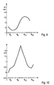
- FIGS. 7 and 8 all deflections have the same sign, ie they all go in the same direction (in contrast to the radially symmetrical distribution according to FIG. 5). Such behavior is realistic and has been observed in many cores at the end of a cycle.
- the edge fuel assembly Q 14 which was already bent at the beginning, shows the maximum deflection.
- the maximum gap width G max also occurs at this edge of the core. It is 4.2 mm.
- the maximum gap width G max (FIG. 10) is also reduced compared to FIG. 8 from approximately 4.2 mm (at the core edge) to approximately 2.5 mm (in the center of the core).
- the equilibrium state occurs in the cycle from the initial conditions for the deformation the edge fuel assemblies, but not from the corresponding initial conditions dependent inside the core.
- the inner fuel assemblies at least at the beginning of the cycle allow trouble-free retraction of the control rods and without Problems are used between the neighboring fuel assemblies can be considered defective and replaced rather, they can be expected to become using the invention (due to the proven interaction with the cooling water) to a tolerable level to bend. So there is no need to pay attention to their deflection to become.
Landscapes
- Physics & Mathematics (AREA)
- Engineering & Computer Science (AREA)
- Plasma & Fusion (AREA)
- General Engineering & Computer Science (AREA)
- High Energy & Nuclear Physics (AREA)
- Monitoring And Testing Of Nuclear Reactors (AREA)
- Structure Of Emergency Protection For Nuclear Reactors (AREA)
Description
- Fig. 1
- einen Querschnitt durch einen Kern eines Druckwasserreaktors;
- Fig. 2
- drei in einem bestrahlten Kern nebeneinander sitzende Brennelemente;
- Fig. 3
- die Situation der Fig. 2 nach Ersetzen des mittleren bestrahlten Brennelementes durch ein unverbogenes, frisches Brennelement;
- Fig. 4
- ein Beispiel einer quer durch den Kern laufenden Reihe aus 14 Brennelementen;
- Fig. 5
- das Maximum der Durchbiegung der in Fig. 4 gezeigten Brennelemente im Gleichgewichtszustand als Funktion ihrer Position, berechnet aus einem ersten, einem frischen Kern entsprechenden Satz von Anfangswerten der Durchbiegung;
- Fig. 6
- die aus dem für Fig. 5 berechneten Gleichgewichtszustand folgende Breite der Spalte zwischen den Brennelementen als Funktion ihrer Position;
- Fig. 7 und 8
- die den Figuren 5 und 6 entsprechenden Funktionen für einen aus einem zweiten Satz von Anfangswerten berechneten Gleichgewichtszustand;
- Fig. 9 und 10
- die den Figuren 5 und 6 entsprechenden Funktionen für einen aus einem dritten Satz von Anfangswerten berechneten Gleichgewichtszustand, wobei dieser dritte Satz der Anfangswerte die Wirkung des erfindungsgemäßen Verfahrens und Kerns belegt,
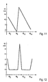
- Fig. 11 und 12
- die den Figuren 7 und 8 entsprechenden Funktionen, wenn der Gleichgewichtszustand ohne Berücksichtigung der Wechselwirkung zwischen Brennelementen und dem Wasser berechnet wird; und
- Fig. 13
- ein Schema für das erfindungsgemäße Verfahren.
Claims (6)
- Verfahren zum Zusammensetzen des Kerns eines Druckwasserreaktors, wobei auf Brennelement-Positionen, für die bestrahlte und gemäß eines vorbestimmten Beladeplanes wiederverwendbare Brennelemente verfügbar sind, solche wiederverwendbaren Brennelemente eingesetzt werden, dadurch gekennzeichnet, dass wiederverwendbare Brennelemente, die durchgebogen sind und am Rand des Kerns eingesetzt werden, dabei derart orientiert werden, dass das Maximum ihrer Durchbiegung auf einer Außenseite des Kernes liegt.
- Verfahren nach Anspruch 1, dadurch gekennzeichnet, dass der Plan für die Positionen am Rand des Kernes Brennelemente mit einer unter dem Mittelwert des Kerns liegenden Reaktivität vorsieht.
- Verfahren nach Anspruch 1 oder 2, dadurch gekennzeichnet, dass in Brennelement-Positionen, die benachbart sind zu den Brennelement-Positionen am Rand des Kerns, durchgebogene Brennelemente eingesetzt werden, und dabei derart orientiert werden, dass ihre Durchbiegungen zum Rand des Kernes weisen.
- Kern eines frisch nachgeladenen Druckwasserreaktors, bei dem in Brennelement-Positionen am Rand des Kerns bestrahlte und durchgebogene Brennelemente eingesetzt sind, dadurch gekennzeichnet, dass diese Brennelemente am Rand derart orientiert sind, dass das Maximum ihrer Durchbiegung auf einer Außenseite des Kerns liegt.
- Kern nach Anspruch 4, dadurch gekennzeichnet , dass jedes Brennelement auf einer Positionen am Rand des Kerns und jedes einem solchen Brennelement benachbarte Brennelement entweder praktisch nicht durchgebogen ist oder eine Durchbiegung besitzt, die vom Kern nach außen weist.
- Kern nach einem der Ansprüche 4 oder 5, dadurch gekennzeichnet, dass die spaltbare Masse jedes am Rand angeordneten Brennelementes unter dem Mittelwert aller Brennelemente des Kerns liegt.
Applications Claiming Priority (5)
| Application Number | Priority Date | Filing Date | Title |
|---|---|---|---|
| DE10124637 | 2001-05-18 | ||
| DE10124637 | 2001-05-18 | ||
| DE10145289A DE10145289A1 (de) | 2001-05-18 | 2001-09-14 | Verfahren zum Zusammensetzen eines Druckwasserreaktor-Kernes und entsprechen nachgeladener Kern |
| DE10145289 | 2001-09-14 | ||
| PCT/EP2002/005057 WO2002095765A2 (de) | 2001-05-18 | 2002-05-08 | Verfahren zum zusammensetzen eines druckwasserreaktor-kernes und entsprechender druckwasserreaktorkern |
Publications (2)
| Publication Number | Publication Date |
|---|---|
| EP1327250A2 EP1327250A2 (de) | 2003-07-16 |
| EP1327250B1 true EP1327250B1 (de) | 2004-02-11 |
Family
ID=26009353
Family Applications (1)
| Application Number | Title | Priority Date | Filing Date |
|---|---|---|---|
| EP02738040A Expired - Lifetime EP1327250B1 (de) | 2001-05-18 | 2002-05-08 | Verfahren zum zusammensetzen eines druckwasserreaktor-kernes und entsprechender druckwasserreaktorkern |
Country Status (5)
| Country | Link |
|---|---|
| US (1) | US7668282B2 (de) |
| EP (1) | EP1327250B1 (de) |
| JP (1) | JP4220784B2 (de) |
| ES (1) | ES2213738T3 (de) |
| WO (1) | WO2002095765A2 (de) |
Families Citing this family (4)
| Publication number | Priority date | Publication date | Assignee | Title |
|---|---|---|---|---|
| DE10358830B3 (de) * | 2003-12-16 | 2005-08-18 | Framatome Anp Gmbh | Brennelement für einen Druckwasserkernreaktor und mit solchen Brennelementen aufgebauter Kern eines Druckwasserreaktors |
| FR2914103B1 (fr) * | 2007-03-19 | 2009-12-18 | Areva Np | Procede de determination de la distribution de puissance volumique du coeur d'un reacteur nucleaire |
| DE102009028793B3 (de) | 2009-07-20 | 2011-01-27 | Areva Np Gmbh | Verfahren und Vorrichtung zum Ermitteln der Verformung eines Brennelementes eines Druckwasserreaktors |
| DE102009047760A1 (de) | 2009-11-12 | 2011-06-09 | Areva Np Gmbh | Verfahren und Vorrichtung zum Ermitteln der Verformung eines Brennelementes eines Druckwasserreaktors |
Family Cites Families (17)
| Publication number | Priority date | Publication date | Assignee | Title |
|---|---|---|---|---|
| US3235463A (en) * | 1958-01-31 | 1966-02-15 | Babcock & Wilcox Co | Nuclear reactor |
| US3048532A (en) * | 1961-05-24 | 1962-08-07 | Ii Arthur G Thorp | Cruciform control rod joint |
| GB1126585A (en) * | 1964-12-30 | 1968-09-05 | Combustion Eng | Nuclear reactor and control rod therefor |
| SE351741B (de) * | 1971-10-11 | 1972-12-04 | Asea Atom Ab | |
| GB1425919A (en) * | 1972-10-02 | 1976-02-25 | Atomic Energy Authority Uk | Nuclear reactor fuelling machine |
| US4451427A (en) * | 1978-02-03 | 1984-05-29 | Combustion Engineering, Inc. | In-core fuel management for nuclear reactor |
| JPS54153986A (en) * | 1978-05-25 | 1979-12-04 | Toshiba Corp | Bending prevention method of reactor fuel |
| JPS55136995A (en) | 1979-04-13 | 1980-10-25 | Hitachi Ltd | Fast breeder |
| FR2603416B1 (fr) * | 1986-08-28 | 1988-12-02 | Framatome Sa | Assemblage combustible pour reacteur nucleaire a reseau evolutif |
| CH672206A5 (de) * | 1987-01-15 | 1989-10-31 | Sulzer Ag | |
| JPS63223590A (ja) * | 1987-03-13 | 1988-09-19 | 株式会社東芝 | 沸騰水型原子炉の炉心構造 |
| JPH01178894A (ja) | 1988-01-07 | 1989-07-17 | Nuclear Fuel Ind Ltd | 原子燃料集合体 |
| JPH02156191A (ja) * | 1988-12-09 | 1990-06-15 | Hitachi Ltd | 原子炉炉心 |
| JPH02161390A (ja) * | 1988-12-14 | 1990-06-21 | Hitachi Ltd | 燃料集合体の装荷方法 |
| JPH02201291A (ja) * | 1989-01-31 | 1990-08-09 | Toshiba Corp | 原子炉の運転方法 |
| JPH04204084A (ja) * | 1990-11-30 | 1992-07-24 | Hitachi Ltd | チャンネルボックスの再使用方法 |
| FR2725298B1 (fr) * | 1994-09-30 | 1996-12-20 | Framatome Sa | Coeur d'un reacteur nucleaire a eau sous pression et embout superieur d'un assemblage de combustible du coeur |
-
2002
- 2002-05-08 JP JP2002592137A patent/JP4220784B2/ja not_active Expired - Fee Related
- 2002-05-08 ES ES02738040T patent/ES2213738T3/es not_active Expired - Lifetime
- 2002-05-08 EP EP02738040A patent/EP1327250B1/de not_active Expired - Lifetime
- 2002-05-08 WO PCT/EP2002/005057 patent/WO2002095765A2/de not_active Ceased
-
2003
- 2003-06-12 US US10/460,812 patent/US7668282B2/en not_active Expired - Fee Related
Also Published As
| Publication number | Publication date |
|---|---|
| JP4220784B2 (ja) | 2009-02-04 |
| US7668282B2 (en) | 2010-02-23 |
| WO2002095765A3 (de) | 2003-03-27 |
| WO2002095765A2 (de) | 2002-11-28 |
| ES2213738T3 (es) | 2004-09-01 |
| JP2004528573A (ja) | 2004-09-16 |
| EP1327250A2 (de) | 2003-07-16 |
| US20040022344A1 (en) | 2004-02-05 |
Similar Documents
| Publication | Publication Date | Title |
|---|---|---|
| DE3828616C2 (de) | ||
| DE69608160T2 (de) | Verfahren zum Reparieren eines Kernbrennstabbündel mit einem geschädigten Stab und einem geschädigten Abstandhaltergitter | |
| DE1589801A1 (de) | Brennstoffbuendel fuer Kernreaktoren | |
| DE69508172T2 (de) | Kernbrennstabbündel mit vergrösserter aktiver Höhe für einen Druckwasserreaktor | |
| DE3139823C2 (de) | Brennstoffbündel | |
| DE2740387A1 (de) | Reaktorkern fuer kernreaktoren | |
| DE69306138T2 (de) | Abstandshalterlamelle mit optimal gestaltetem Abstand zwischen Brennstabbündel und Kasten in einem Siedewasserreaktor | |
| EP0364623B1 (de) | Brennelement, insbesondere für einen Druckwasser-Kernreaktor | |
| DE3301965A1 (de) | Aus elementen zusammengesetzter kern fuer einen kernreaktor | |
| DE2547791C3 (de) | Brennelementkassette | |
| DE2515709A1 (de) | Verfahren zur bearbeitung eines brennmaterials fuer einen kernreaktor | |
| DE69508171T2 (de) | Dreieckige Gitteranordnung für viereckige Leichtwasserkernreaktorbrennstabbündel | |
| DE69208932T2 (de) | Entfernbare Federn für Röhrchenabstandshalter in einem Kernreaktor | |
| DE2040497A1 (de) | Brennstoffanordnung fuer einen Kernreaktor | |
| DE2849395A1 (de) | Brennelement fuer fluessigkeitsgekuehlte brutreaktoren | |
| DE69718316T2 (de) | Kernbrennstoffeinheit | |
| DE2839211C2 (de) | ||
| DE3525273A1 (de) | Steuerstabkonstruktion fuer siedewasserreaktoren | |
| EP1327250A2 (de) | Verfahren zum zusammensetzen eines druckwasserreaktor-kernes und entsprechender druckwasserreaktorkern | |
| DE2749583C3 (de) | Kernbrennelement mit einer Abstandshalteeinrichtung | |
| DE69308050T2 (de) | Manschettenartiger Abstandshalter mit reduziertem Druckverlust | |
| DE10145289A1 (de) | Verfahren zum Zusammensetzen eines Druckwasserreaktor-Kernes und entsprechen nachgeladener Kern | |
| DE2815200B2 (de) | Aus Brennstoffbaugruppen bestehender Kern eines Kernreaktors zur Leistungserzeugung und Verfahren zu seinem Betrieb | |
| DE2656590A1 (de) | Verfahren zur ermoeglichung von einsparungen bei kernreaktoren durch verwendung von berylliumstaeben in brennstoffbuendeln | |
| EP1611584A2 (de) | Brennelement für einen druckwasserkernreaktor |
Legal Events
| Date | Code | Title | Description |
|---|---|---|---|
| PUAI | Public reference made under article 153(3) epc to a published international application that has entered the european phase |
Free format text: ORIGINAL CODE: 0009012 |
|
| 17P | Request for examination filed |
Effective date: 20030408 |
|
| AK | Designated contracting states |
Designated state(s): AT BE CH CY DE DK ES FI FR GB GR IE IT LI LU MC NL PT SE TR |
|
| GRAP | Despatch of communication of intention to grant a patent |
Free format text: ORIGINAL CODE: EPIDOSNIGR1 |
|
| GRAS | Grant fee paid |
Free format text: ORIGINAL CODE: EPIDOSNIGR3 |
|
| GRAA | (expected) grant |
Free format text: ORIGINAL CODE: 0009210 |
|
| AK | Designated contracting states |
Kind code of ref document: B1 Designated state(s): CH DE ES FR LI SE |
|
| REG | Reference to a national code |
Ref country code: CH Ref legal event code: EP |
|
| REG | Reference to a national code |
Ref country code: IE Ref legal event code: FG4D Free format text: GERMAN |
|
| REG | Reference to a national code |
Ref country code: CH Ref legal event code: NV Representative=s name: E. BLUM & CO. PATENTANWAELTE |
|
| REF | Corresponds to: |
Ref document number: 50200243 Country of ref document: DE Date of ref document: 20040318 Kind code of ref document: P |
|
| REG | Reference to a national code |
Ref country code: ES Ref legal event code: FG2A Ref document number: 2213738 Country of ref document: ES Kind code of ref document: T3 |
|
| REG | Reference to a national code |
Ref country code: IE Ref legal event code: FD4D |
|
| ET | Fr: translation filed | ||
| PLBE | No opposition filed within time limit |
Free format text: ORIGINAL CODE: 0009261 |
|
| STAA | Information on the status of an ep patent application or granted ep patent |
Free format text: STATUS: NO OPPOSITION FILED WITHIN TIME LIMIT |
|
| 26N | No opposition filed |
Effective date: 20041112 |
|
| REG | Reference to a national code |
Ref country code: CH Ref legal event code: PFA Owner name: AREVA NP GMBH Free format text: FRAMATOME ANP GMBH#FREYESLEBENSTRASSE 1#91058 ERLANGEN (DE) -TRANSFER TO- AREVA NP GMBH#FREYESLEBENSTRASSE 1#91058 ERLANGEN (DE) |
|
| REG | Reference to a national code |
Ref country code: FR Ref legal event code: CD |
|
| REG | Reference to a national code |
Ref country code: CH Ref legal event code: PFA Owner name: AREVA NP GMBH Free format text: AREVA NP GMBH#FREYESLEBENSTRASSE 1#91058 ERLANGEN (DE) -TRANSFER TO- AREVA NP GMBH#FREYESLEBENSTRASSE 1#91058 ERLANGEN (DE) |
|
| REG | Reference to a national code |
Ref country code: CH Ref legal event code: PCOW Free format text: AREVA NP GMBH;PAUL-GOSSEN-STRASSE 100;91052 ERLANGEN (DE) |
|
| REG | Reference to a national code |
Ref country code: FR Ref legal event code: CA |
|
| PGFP | Annual fee paid to national office [announced via postgrant information from national office to epo] |
Ref country code: FR Payment date: 20110603 Year of fee payment: 10 Ref country code: SE Payment date: 20110523 Year of fee payment: 10 Ref country code: ES Payment date: 20110524 Year of fee payment: 10 Ref country code: CH Payment date: 20110525 Year of fee payment: 10 |
|
| PGFP | Annual fee paid to national office [announced via postgrant information from national office to epo] |
Ref country code: DE Payment date: 20110720 Year of fee payment: 10 |
|
| REG | Reference to a national code |
Ref country code: CH Ref legal event code: PL |
|
| REG | Reference to a national code |
Ref country code: SE Ref legal event code: EUG |
|
| PG25 | Lapsed in a contracting state [announced via postgrant information from national office to epo] |
Ref country code: CH Free format text: LAPSE BECAUSE OF NON-PAYMENT OF DUE FEES Effective date: 20120531 Ref country code: LI Free format text: LAPSE BECAUSE OF NON-PAYMENT OF DUE FEES Effective date: 20120531 |
|
| PG25 | Lapsed in a contracting state [announced via postgrant information from national office to epo] |
Ref country code: SE Free format text: LAPSE BECAUSE OF NON-PAYMENT OF DUE FEES Effective date: 20120509 |
|
| REG | Reference to a national code |
Ref country code: FR Ref legal event code: ST Effective date: 20130131 |
|
| REG | Reference to a national code |
Ref country code: DE Ref legal event code: R119 Ref document number: 50200243 Country of ref document: DE Effective date: 20121201 |
|
| PG25 | Lapsed in a contracting state [announced via postgrant information from national office to epo] |
Ref country code: FR Free format text: LAPSE BECAUSE OF NON-PAYMENT OF DUE FEES Effective date: 20120531 |
|
| PG25 | Lapsed in a contracting state [announced via postgrant information from national office to epo] |
Ref country code: DE Free format text: LAPSE BECAUSE OF NON-PAYMENT OF DUE FEES Effective date: 20121201 |
|
| REG | Reference to a national code |
Ref country code: ES Ref legal event code: FD2A Effective date: 20130820 |
|
| PG25 | Lapsed in a contracting state [announced via postgrant information from national office to epo] |
Ref country code: ES Free format text: LAPSE BECAUSE OF NON-PAYMENT OF DUE FEES Effective date: 20120509 |