EP1326474A2 - Dispositif et procédé de commutation de données optiques pour réseaux de communication optiques - Google Patents
Dispositif et procédé de commutation de données optiques pour réseaux de communication optiques Download PDFInfo
- Publication number
- EP1326474A2 EP1326474A2 EP02293234A EP02293234A EP1326474A2 EP 1326474 A2 EP1326474 A2 EP 1326474A2 EP 02293234 A EP02293234 A EP 02293234A EP 02293234 A EP02293234 A EP 02293234A EP 1326474 A2 EP1326474 A2 EP 1326474A2
- Authority
- EP
- European Patent Office
- Prior art keywords
- input
- output
- wavelength
- conversion
- ports
- Prior art date
- Legal status (The legal status is an assumption and is not a legal conclusion. Google has not performed a legal analysis and makes no representation as to the accuracy of the status listed.)
- Withdrawn
Links
Images


Classifications
-
- H—ELECTRICITY
- H04—ELECTRIC COMMUNICATION TECHNIQUE
- H04Q—SELECTING
- H04Q11/00—Selecting arrangements for multiplex systems
- H04Q11/0001—Selecting arrangements for multiplex systems using optical switching
- H04Q11/0005—Switch and router aspects
-
- H—ELECTRICITY
- H04—ELECTRIC COMMUNICATION TECHNIQUE
- H04Q—SELECTING
- H04Q11/00—Selecting arrangements for multiplex systems
- H04Q11/0001—Selecting arrangements for multiplex systems using optical switching
- H04Q11/0005—Switch and router aspects
- H04Q2011/0007—Construction
- H04Q2011/0011—Construction using wavelength conversion
-
- H—ELECTRICITY
- H04—ELECTRIC COMMUNICATION TECHNIQUE
- H04Q—SELECTING
- H04Q11/00—Selecting arrangements for multiplex systems
- H04Q11/0001—Selecting arrangements for multiplex systems using optical switching
- H04Q11/0005—Switch and router aspects
- H04Q2011/0007—Construction
- H04Q2011/002—Construction using optical delay lines or optical buffers or optical recirculation
Definitions
- the invention relates to the transmission of data in communication networks. optics. It is intended more particularly for architectures of matrixes of switching which, within the nodes of the network, are intended to route data to different network links and devices. These matrices must be able to realize, at need, conversions of wavelength ⁇ of the carrier of the switched data, in particular to multiplex them and / or solve contention problems in their transport on the same fiber.
- the data can be in the form of packets to time division multiplexing or wavelength division multiplexing, or possibly in the form of a continuous flow from end to end according to a circuit mode.
- optical packet switching matrices is based full flexibility for carrier wavelength conversion on all ports input: each input signal can therefore be sent to any output port, and this on any carrier wavelength accepted by the network, thanks to wavelength converters associated with output ports.
- Figure 1 is a diagram illustrating the principle of an optical network of data communication 2, composed of a set of nodes, some of which 4 operate only within the network and other 4 ', connected to them, are located at the periphery of the network to establish connections with the outside, for example example with a gateway.
- Each of nodes 4 or 4 ' comprises at least one matrix of switching whose ports are connected to links 6 internal to network 2, as well as to lines 8 for connection to the network with regard to the peripheral nodes 4 ′.
- the links 6 and connection lines 8 consist of optical fibers which, in the example considered, allow several data packets to be carried simultaneously on a strand by WDM multiplexing.
- Figure 2 shows in a very simplified way an example of classical architecture a switching matrix 10 of a node 4 or 4 'of the network 2.
- n x n that is to say composed of a number n of input ports PE1 to PEn (generic designation PE) and of the same number n of output ports PS1 to PSn (generic designation PS).
- Each input port is connected to an input fiber optic cable, respectively FE1 to FEn and, similarly, each output port is connected to a fiber optic cable of output FS1 to FSn.
- Each input and output fiber optic cable can carry a number L of different carrier wavelengths ⁇ 1 to ⁇ L, their respective ports being adapted to operate in multiplexing and / or demultiplexing on all of these L wavelengths.
- An interconnection unit 12 is interposed between the PE input and output ports PS so that each wavelength of each input port can be linked to the set of L wavelengths of the n output ports, as shown symbolically the crossed lines within this unit.
- a delay unit 14 is provided to allow a value of delay selected on the lines connecting the input and output ports of the interconnection 12. These delays make it possible in particular to settle disputes when multiple data channels want to access the same wavelength at the same time on the same output port.
- Figure 3 shows in more detail part of the matrix in Figure 2 at the input ports PE1 and PEn and at the output ports PS1 and PSn, as well as some of the interconnections between these ports. It will be understood that all the ports input PE1 to PEn have a substantially identical internal architecture, the same for each of the output ports PS1 to PSn. All of the different interconnections between these ports can also be deduced by simple extrapolation.
- Each input port PE has, at the fiber optic input FE, a demultiplexer, 16 to L output channels, 16-1 to 16-L (generic designation 16), each of these channels separately presenting any modulated signal present on the FE input fiber.
- a demultiplexer 16 to L output channels, 16-1 to 16-L (generic designation 16), each of these channels separately presenting any modulated signal present on the FE input fiber.
- On each of these channels 16-1 to 16-L is placed a first wavelength converter, respectively 18-1 to 18-L (generic designation 18), which allows the data to be output presented to it at the output of the demultiplexer 16 at a wavelength ⁇ 1 to ⁇ L which his own.
- the converters are generally made on the basis of devices of semiconductor optical amplification, known and designated below by their acronym Anglo-Saxon SOA (from “semiconductor optical amplifier”), and therefore also has amplification or even regeneration properties.
- each first converter 18 is presented to a respective input a first multiplexer 20 to L inputs allowing to group, on the same channel output 22, all the outputs of the converters 18-1 to 18-L.
- the first n corresponding multiplexers 20 have as many respective output channels 22-1 to 22-n (generic designation 22).
- the set described therefore allows, for each input port PE1 to PEn, to present at the output the signals present on FE1 to FEn input fibers, converted on internal carrier lengths ( ⁇ 1 to ⁇ L).
- the assembly constituted by the demultiplexer 16, the converter 18 and the first multiplexer 20 forms a conversion stage and input amplification.
- each first multiplexer 20 which constitutes a single channel, is presented to a respective input of a number K of optical delay lines 24-1 to 24-K (generic designation 24) of the delay unit 14.
- the configuration provides K delay lines specific to each output 22 of the first multiplexer, although in practice these lines can be shared, if the wavelengths coming from different input multiplexers are different.
- Each of the delay lines in a 24-1 set at 24-K imposes a specific amount of delay.
- the range of delays begins with the zero value (zero delay), materialized by a direct connection on line 24-1.
- the relationship between the different delays typically follows a progression linear, for example the smallest non-zero delay imposed (line 24-2) will have a value ⁇ , the following lines of the progression respectively imposing a delay ⁇ , 2 ⁇ , 3 ⁇ , ....
- the value ⁇ is equal to the fixed size (temporal occupation) of the packet.
- the k outputs of the delay lines of each input port constitute outputs buffer, allowing a temporal distribution of data arriving simultaneously, and including concatenating them.
- Each output port PS1 to PSn includes L groups of inputs 26-1 to 26-L (generic designation 26), each group having a number n * K of individual entries linked to receive respective output from the K delay lines for each of the n ports PE inlet.
- Each group of n * K entries 26-1 to 26-L is received by a first block of selection 27-1 to 27-L, allowing the selection of a PE input port among the n, with a delay k (between 1 and K)
- the data selected by these selection blocks 27-1 to 27-L are then diffused by a respective star optical coupler assembly 28-1 to 28-L (generic designation 28) at L outputs.
- each of the L outputs is connected to a second selection block 29 with L inputs and L outputs. These L outings are connected to a second respective multiplexer 30-1 to 30-L (generic designation 30).
- Figure 4 shows in more detail the chain consisting of a first selection block 27, a star optical coupler assembly 28 and a second block of selection 29.
- the first selection stage 27 includes an SOA specific to each of the n * K entries, i.e. n * K entry SOA (SOA-E) in total. Each of these is used as that optical door for the selection of an input line.
- SOA-E selected is set to "on" (switch closed) to start the data past, the n * K-1 other SOA-E being in "off" position (switch open) to block data on their respective channels.
- the second selection block 29 includes an SOA specific to each of the L total, i.e. L total SOA (SOA-S). Each of these is used as that PO optical door for the selection of a wavelength in association with the input of the multiplexer 30.
- SOA-S L total SOA
- a selected SOA-S is put in position “on” (switch closed) to launch past data, L-1 other SOA-S being in "off” position (switch open) to block data on their channels respectively.
- each of the L second multiplexers 30 is connected to a second respective wavelength converter 34-1 to 34-L (generic designation 34) before attacking the FS output fiber of the port.
- These second converters 34 convert the data presented to it as input any of the L different wavelengths ⁇ 1 to ⁇ L toward the lengths associated with each group. Note that these second converters also serve as regenerators: they perform in addition to this wavelength conversion function, a regeneration at each output of the optical packet switching matrices in order also to recover the quality of the optical signals and to allow cascading of multiple switching matrices.
- each of the L second converter 34 is presented to an input respective of a third multiplexer 36 to L input channels and an output channel, this the latter being connected to the port FS output fiber. So any output port can transmit on its FS output fiber any data received on the different inputs of the input ports PE1 to PEn, and this on any of the wavelengths ⁇ 1 to ⁇ L, with resolution of possible restraints by adapting the carrier wavelength (resolution spectral) or by imposition of delay (temporal resolution).
- internal port means any internal input or output of the switching matrix.
- the number of internal ports comprising semiconductor optical amplifiers SOA-E (first selection block 27) and SOA-S (second selection block 29), is very large, even in operation in multiplexing mode with wavelength distribution. Indeed, it is necessary to provide nK + L internal ports for each output wavelength, which implies in total nL * (nK + L) semiconductor optical amplifiers. This classic solution therefore involves a so-called complete conversion. Furthermore, due to the considerable optical losses in the optical distributors of the matrix and of the cascade of optical semiconductor amplifiers, the degradations of the optical signals of the matrix require the presence of regeneration interfaces, namely the demultiplexer elements 16 / converter 18 and multiplexer 18 above.
- the invention proposes simplified node architectures based on only partial use of length conversion / regeneration wave, in order to soften the material volume constraints of the switching matrices optics.
- the conversion means are limited in the wavelength conversion capability so that the conversion can intervene for the emission of a signal from an input port by any output port, but with carrier wavelength conversion possible, with each of the output ports, only towards a limited number x1 of wavelength values among the number L of distinct wavelength values accepted as input, x1 being greater than 0 and less than L.
- the conversion means are limited in the wavelength conversion capability so that the conversion can intervene for the emission of a signal from an input port with wavelength conversion possible to any wavelength value among the number L of length values separate waveforms accepted as input, but only for switching on a restricted number x2 of output ports, x2 being greater than 0 and less than the number of device output ports.
- the device can be of the type able to switch the signals in the form optical data packets.
- the limitation of the conversion means may intervene at at least one of the output ports, each output port to which there is the limitation comprising a first number of signal line inputs in coming from the input ports, and a second number L of output lines, this second number representing the number of distinct wavelengths on the PS output ports, and in that among this second number at least one of the output lines is devoid of wavelength conversion means, used only for outputting a signal with the same wavelength as that at which this signal is received as input.
- Each output port involves a length conversion limitation wave can include a simplified selection block, allowing to group on each output line without conversion signals from input lines having the same wavelength as that of the output line, the block further comprising, for each output line without conversion, spatial selection means for line selection input, these selection means being devoid of spectral selection means and coupled at the output, by coupling means, to the output line corresponding to the wavelength of the spatial selection block.
- It may further comprise time selection means for delaying a input port signal before it is output from an output port, the means of time selection presenting to the output ports a number K of copies of received signals on the input ports, each copy being offset in time relative to the others.
- Each output port involves a length conversion limitation wave can include a set of input lines leading to output lines devoid of conversion means, the assembly comprising, for a number n of ports input, a number n * K of lines, one for each of said K copies shifted in the time from each of the n input ports.
- K lines of the set can be presented at the input of the selection block simplified, the latter producing a number of output lines (L-x1) equal to the total number L of distinct wavelength values accepted at the input of the device minus said restricted number x1 of wavelength values for which a carrier wavelength conversion is possible.
- the device can also comprise a multiplexer with L inputs receiving respectively each of the (L-x1) output lines of the simplified selection blocks and the x1 outputs of all the multiplexers, and one output emitting on an output fiber the corresponding output port.
- K lines of the set can be presented at the input of the selection block simplified, the latter producing a number of output lines equal to the number total L of wavelength values accepted at the input of the device.
- It may further comprise a multiplexer with L inputs receiving respectively each of the output lines of said simplified selection blocks and an output on a fiber corresponding output port.
- the invention relates to an optical communication network comprising at least one node making it possible to connect input and output lines, characterized in that said node comprises at least switching device according to the first aspct, connected to a set of input lines on its input ports and to a set output lines on its output ports.
- the switching device can then be further connected to at least one gateway.
- the network can manage contention by time distribution of packets, especially when packets in contention cannot be converted from wavelength due to the limitation of wavelength conversion capacity, and by spectral and temporal distribution, in particular when the packet in contention can be the subject of a wavelength conversion.
- the invention relates to the use of a device for switching according to the first aspect for flow switching in a network node communication, with content management by time distribution of flows, especially when contention flows cannot be converted from wavelength due to said limitation of length conversion capacity wave, and by spectral and temporal distribution, especially when the flow in contention may be subject to wavelength conversion.
- the invention relates to the finding by the plaintiff that, depending on the network architecture considered, the conversion / regeneration on all of the wavelengths and / or at each optical path of input or output is not always required in optical switching arrays, such as those that manage optical packages.
- the use of such converters / regenerators in order to simplify the architecture of the nodes for example by equipping only on certain ports or only partially on each port. In this way, since there is no provision for full wavelength conversion (i.e.
- the only contention entry wavelengths for a given output wavelength ⁇ i are the wavelengths of this same value ⁇ i at each input fiber.
- the second level of wavelength selection performed by the set optical interconnection 29 with converters 34 according to the architecture according to FIGS. 3 and 4 can be removed, or at least greatly simplified at an output port given. Indeed, systematic wavelength selection is no longer necessary, and the size of the optical couplers for diffusion (1: nL couplers) can be reduced.
- L denotes the number of possible carrier wavelengths for the signals processed by the switching matrix
- n denotes the number of input ports or the number of switch fabric output ports.
- full conversion means the possibility of converting any length at the input of a set of wavelengths ⁇ 1 to ⁇ L to any other wavelength of this together.
- a possibility of conversion reduced to the fraction of x1 / L or x2 / n possibilities respectively means that only the number x1 of L wavelengths can be converted, for a given port, or only the number x2 of the n ports of output will not have full conversion means to any of the lengths wave ⁇ 1 to ⁇ L.
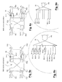
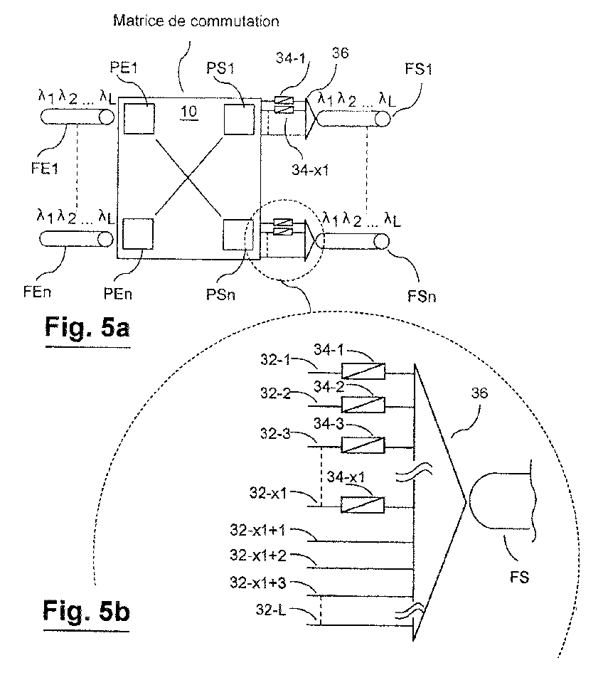
- FIGS 5a and 5b show in a simplified manner a switching matrix "n x n" 10 as shown in Figures 3 and 4, with its connections to FE input fibers and FS output.
- the n input ports PE1 to PEn can be of structure similar to that of Figure 3, and will not be described again for the sake of brevity.
- the simplification of the architecture according to the invention limits the losses and can make this floor unnecessary.
- each of the input fibers FE1 to FEn drives an optical coupler (not shown) which feeds the respective K inputs of the delay lines 24-1 to 24-K; fibers FE1 to FEn are then directly connected to points 22-1 to 22-n in Figure 3.
- n output ports PS is carried out in a simplified way by providing only a number x1 of the L outputs 32-1 to 32-L of port are provided to be connected to a conversion / regeneration stage respectively 34-1 to 34-x1, as shown more precisely by the magnifying glass on the outputs shown in Figure 5b.
- the upstream optical paths, namely the multiplexer 30, the optical coupler 28 and the group of inputs 26 are in similar to those in Figure 3.
- a 2x2 switch with four wavelengths per port. on the output ports, the wavelengths ⁇ 1 and ⁇ 2 are with conversion and the lengths ⁇ 3 and ⁇ 4 are without conversion.
- On groups 1 and 2 we can receive packages coming from ⁇ 1, ⁇ 2, ⁇ 3 and ⁇ 4 on one of the two input ports, while on port 3 and 4, we can only receive packets from ⁇ 3 and ⁇ 4 respectively on one of the two ports input. distribution (after delays) is therefore 6 instead of 8 in a conversion case complete.
- FIGS. 6a and 6b are diagrams similar to those of FIGS. 5a and 5b.
- the x2 / n fractionation of the conversion capacities is ensured by providing that only a number x2 of the n output ports PS1 to PSn have all the conversion and regeneration capabilities.
- Each of these x2 ports is therefore at all points identical to an output port PS of FIG. 3, its n outputs 32-1 to 32n attacking the multiplexer 36 of its FS output fiber also via L conversion / regeneration stages respectively 34-1 to 34-L.
- the simplification then comes from the n-x2 other output ports PSx2 + 1 to PSn, for which do not provide an output conversion and regeneration stage.
- the L outputs 34-1 at 34-L from each of these n-x2 other ports directly attack multiplexer 36 in head of its FS output fiber.
- the complexity of the optical matrix of switching is greatly reduced compared to the prior art, because the diffusion in the switching matrix is only partial.
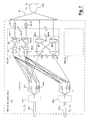
- FIG 7 shows in more detail the internal architecture of a matrix of switching 40 in accordance with variant 1 above, the general structure of which is described with reference to Figures 5a and 5b.
- All n output ports so designated generic by PSCP (output port with partial conversion) are identical, and only one PSCP1 which attacks the output fiber FS1 is shown in detail.
- all n input ports are identical, and only the outputs 1 to k of the lines are shown delay from two of these, in this case the input ports PE1 and PEs (cf. figure 3).
- the total conversion with regeneration wavelength is provided by the first x1 groups of entries 26-1 to 26-x1, of which only the first and th x1 are shown.
- the optical processing paths and means are the same as for any other input group 26 in FIG. 3. There is therefore, for each one, successively: a coupling assembly nK: L 28, a second multiplexer 30 and a conversion / regeneration stage 34.
- the output of each of these x1 stages 34-1 to 34-x1 attacks the output multiplexer 36 at the head of the output fiber FS.
- the L-x1 other inputs of this output multiplexer 36 come directly an optical selection structure 42 which collects n * K delay line outputs, each on a respective demultiplexer 44. More precisely, the optical selection structure 42 receives on its respective n * K multiplexers 44 the K outputs of the delay lines 24-1 to 24-4 for each of the n input ports PE1 to PEn.
- the L-x1 outputs of these n * K demultiplexers 44 are collected by a set of strips of selection composed of a number d of selection bars 46-1 to 46-d, where d is equal to L-x1.
- Each bar receives the data carried by the same wavelength but coming n * K demultiplexers 44.
- nK 1 respective 48-1 to 48-d (generic designation 48) any of inputs presented to an input port fiber FE1 to FEn with any of the K possible delays by delay lines 24-1 to 24-K, but only at wavelength original present at the input fiber.
- Each output of couplers 48 is presented on the respective input of the output multiplexer 36 corresponding to the wavelength in output of each selection block 46.
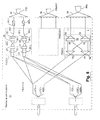
- FIG 8 shows in more detail the internal architecture of a matrix of switching 50 according to variant 2 above, the general structure of which is described with reference to Figures 6a and 6b.
- PSCC generator complete
- PSSC generator designation
- Their operation and their connections to the n input ports PE1 to PEn via the delay lines 24-1 to 24-n conform to the description with reference to Figure 3 and do not will not be repeated for the sake of brevity.
- the output fibers FS1 to FSx2 of these ports PSCC therefore allow each to retransmit all data presented on the ports input PE1 to PEn, with the possibility of selection from the K delays, regardless of which of the L wavelengths.
- the n-x2 other output ports without PSSCx2 + 1 to PSSCn conversion do not do not provide for wavelength conversion of the data presented to their inputs.
- Their function is limited to selecting on their respective FS output fiber all data presented on the input ports PE1 to PEn, with the possibility of selection among the K delays in resolving wavelength by wavelength contention
- each output port without PSSC conversion includes a set of selection 52 to n * K inputs, respectively one for each of the n input ports PE1 to PEn, multiplied by each of the K delay possibilities.
- Selection set 52 has a number n * K of demultiplexers 54, one for each input, and a number L selection bars 56, each associated with a coupler 58, like the set of selection 42 of FIG. 7.
- the output of each of the n * K demultiplexers 54 is transmitted to each of the L selection bars 56, each of the bars treating only one wave length.
- the L couplers 58 directly drive the respective inputs of the output multiplexer 36, by associating the output wavelengths of the blocks one by one selection 56 with the input wavelengths of the multiplexer 36, so that this the latter can output one of the n * K inputs on its associated output fiber.
- Diffusion is only total towards output lengths with conversion, so that a limited diffusion is sufficient towards the ports without conversion, the complement of diffusion being provided by spectral demultiplexing and one-to-one correspondence between input wavelengths and output wavelengths. So the selection is similar to that of Figure 3 for ports with wavelength conversion / regeneration (in the occurrence, two stages of optical doors), but it is simplified for the ports without wavelength conversion, the latter requiring only one stage of doors optical (there is no additional active wavelength selection stage, the wavelength selection being carried out passively by means of the demultiplexer 44 in the first case or 54 in the second case).
- L should preferably be less than 32 in order limit the number of wavelengths in each amplifier.
- the architecture can be modified in accordance with French patent application FR 0015889, using band demultiplexing at the input (b bands intended to have L / b wavelengths by amplifier).
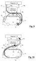
- Figures 9 and 10 illustrate examples of the operation of an optical matrix optical packet switching according to either of variants 1 and 2 of the invention for routing packet data to a node of an optical network having a local connection gateway.
- a switching matrix 60 which can be in particular in accordance with that 40 of FIG. 7 or that 50 of FIG. 8, is connected with a part to a gateway 70 and secondly to an optical network 2 in the form of a ring. More in particular, at least one gateway output is connected to a PEp input port respective matrix 60, and at least one output port PSp thereof is connected to a respective entrance to the bridge. These PEp and PSp ports therefore allow the gateway 70 respectively send and receive optical data packets on the network, according to a conventional connection. Typically, the gateway is used to provide connection between the network and a subnetwork, for example a metropolitan network.
- the other input and output ports of the switching matrix 60 are connected to the network in order to allow on the one hand to route transit data in the network and on the other hand to extract or introduce the data to the gateway account.
- gateway 70 Communications between gateway 70 and the network are managed by a protocol MAC type.
- This protocol used in particular in the absence of memory on the route, guarantee that the packages at the source end up at their destination. In this case, the packets remain on a carrier of the same wavelength over their entire end-to-end path
- paths through the matrix are provided which can be used without conversion wavelength and also paths with wavelength conversion for settle cases of contention.
- the choice to use or not a wavelength conversion at the level of the matrix 60 is also managed by the MAC protocol.
- the partial conversion switching according to the invention then makes it possible to respond to all the needs and at the same time to simplify the architecture.
- data is sent from the gateway 70 to an input port PEp of the switching matrix 60 (arrowed lines F1).
- data traffic flows in transit through the matrix (arrowed lines F2 and F3).
- the flow management through the switching matrix then calls upon a partial conversion of wavelength by fiber, with compression resolution achieved by the MAC protocol. Part of the traffic is therefore routed without conversion, and only the traffic in contention is subject to a wavelength conversion.
- data (arrows F4 and F5) of the network 2 over respective lengths are switched by the switching matrix 60 to gateway 70, with parallel data flowing in transit through the matrix (arrow lines F6 and F7).
- Contentions resolution is managed by the MAC protocol for the ring forming the network, and there is no contention between the matrix and the gateway (if we have as many wavelengths on the PE input port of the matrix connected to the ring as on the PSp output port). If a terminal connected to the gateway can access the matrix with a given wavelength, this will always remain available for the communication between the matrix 60 and the gateway 70, since there is no contention with traffic coming from PEp
Landscapes
- Engineering & Computer Science (AREA)
- Computer Networks & Wireless Communication (AREA)
- Optical Communication System (AREA)
- Use Of Switch Circuits For Exchanges And Methods Of Control Of Multiplex Exchanges (AREA)
Abstract
Description
- de multiplexeurs qui permettent de faire converger vers une même fibre différentes voies de données séparées,
- de démultiplexeurs qui permettent, à l'inverse, d'extraire les différentes voies d'un ensemble multiplexé sur des fibres respectives, si la matrice gère des données à multiplexage par répartition en longueurs d'onde,
- de convertisseurs de longueur d'onde, lesquels ont généralement la fonction supplémentaire d'amplifier un signal optique, et
- le cas échéant, des lignes à retard qui agissent en tant que tampon pour permettre de séparer des flots de données dans le temps, notamment pour résoudre des problèmes de contention.
- une première étape dans laquelle, parmi ces n*K entrées, on n'en sélectionne au moyen des SOA-E du premier bloc de sélection 27 qu'une à un instant donné, par activation (interrupteur fermé) du SOA-E correspondant. Ce bloc 27 constitue ainsi un premier étage de sélection. L'ensemble (L longueurs d'onde) des données venant de le port d'entrée (désigné PEj) avec le retard (désigné pK) est alors diffusé par le coupleur étoile n*K:L 28 vers les L SOA-E du deuxième bloc de sélection 29 ; et
- une deuxième étape pour sélectionner la longueur d'onde λi au niveau de deuxième bloc de sélection 29, qui constitue le deuxième étage de sélection. On active (interrupteur fermé) le SOA-S correspondant à longueur d'onde λi, de sorte que l'ensemble des données (L longueurs d'onde) est envoyé vers port i du multiplexeur. On obtient donc uniquement en sortie les données provenant de la longueur λi du port d'entrée PEj ayant subi dans la matrice le retard pK.
caractérisé en ce que lesdits moyens de conversion sont limités dans ladite capacité de conversion de longueur d'onde par au moins l'un des trois moyens de limitation i) à iii) :
- un étage de sélection spatiale et temporel recevant en entrée un nombre n*K de lignes d'entrée, une pour chacune desdites K copies décalées dans le temps provenant de chacun des n ports d'entrée et produisant, par l'utilisation d'un coupleur nK :L, un nombre L de sorties égal au nombre total L de valeurs de longueurs d'onde acceptées en entrée du dispositif,
- un ensemble de sélection de longueur d'onde, constitué d'un étage de sélection spatiale associé à un multiplexeur, recevant en entrée lesdites L sorties et produisant sélectivement l'une d'elles en sortie, et
- un moyen de conversion de longueur d'onde, recevant en entrée la sortie dudit multiplexeur et relié en sortie à une ligne de sortie.
- un premier étage tampon permettant d'imposer un nombre K de copies mutuellement décalées dans le temps de chacune des n signaux optiques en entrée,
- un deuxième étage pour transformer chacun des n*K multiplex issus du premier étage en un nombre de copies égal à n'*(x1+1), et
- un troisième étage de sélection permettant de sélectionner L signaux optiques parmi les nK(x1+1) multiplex reçus par un port de sortie PS.
- un premier étage tampon permettant d'imposer des un nombre K de copies mutuellement décalées dans le temps de chacune des n signaux optiques en entrée,
- un deuxième étage pour transformer chacun des n*K signaux issus de premier étage en un nombre de copies égal à L*x2+n'-x2, et
- un troisième étage de sélection permettant de sélectionner L signaux optiques parmi les n*KL multiplex reçus par un port de sortie avec conversion totale et permettant de sélectionner L signaux optiques parmi les n*K multiplex reçus par un port de sortie sans conversion.
caractérisé en ce que l'on limite la capacité de conversion de longueur d'onde en utilisant au moins l'une des trois possibilités de limitation i) à iii) :
- la figure 1, déjà décrite, est un schéma simplifié d'un réseau de communication optique dans lequel l'invention peut être mise en oeuvre ;
- la figure 2, déjà décrite, est un schéma bloc général simplifié d'un matrice de commutation optique, montrant notamment les relations entre les unités de ports d'entrée et de sortie ;
- la figure 3, déjà décrite, est un schéma bloc plus détaillée d'une matrice optique de commutation, montrant des éléments internes de l'architecture des unités de ports d'entrée et de sortie, ainsi que des tampons à ligne à retard utilisés ;
- la figure 4, déjà décrite, est un schéma détaillé montrant les SOA qui interviennent dans deux étages successifs de sélection en sortie de la matrice optique de la figure 3 ;
- la figure 5a est un schéma simplifié de l'architecture d'une matrice optique de commutation conforme à une première variante de l'invention ;
- la figure 5b est une loupe sur la figure 5a, montrant de façon plus détaillée les sorties d'un port de sortie de la matrice ;
- la figure 6a est un schéma simplifié de l'architecture d'une matrice optique de commutation conforme à une deuxième variante de l'invention ;
- la figure 6b est une loupe sur la figure 6a, montrant de façon plus détaillée les sorties d'un port de sortie de la matrice ;
- la figure 7 est un schéma plus détaillé d'une architecture de port de sortie et de certaines connexions internes conformes à la première variante de l'invention ;
- la figure 8 est un schéma plus détaillé d'une architecture de port de sortie et de certaines connexions internes conformes à la deuxième variante de l'invention ;
- la figure 9 est un schéma de mise en oeuvre d'une matrice optique de commutation conforme à l'invention dans un réseau avec branchement sur une passerelle, présentant un cas de fonctionnement avec des flux partant de la passerelle ; et
- la figure 10 est un schéma de mise en oeuvre d'une matrice de commutation conforme à l'invention dans un réseau avec branchement sur une passerelle, présentant un cas de fonctionnement avec des flux arrivant à la passerelle.
- variante 1 : tous les ports ne disposent que d'un certain nombre de longueurs d'onde pour lesquelles il y a possibilité de la conversion, ce qui constitue la solution désignée ci-après "x1/L possibilités de conversion de longueur d'onde λ sur tous ports", où x1 désigne ci-après un nombre entier supérieur à 0 et inférieur à L, et
- variante 2 : certains ports de sortie n'ont aucune capacité de conversion, et d'autres ont la possibilité conversion complète, ce qui constitue la solution désignée ci-après "x2/n ports à conversion complète de longueur d'onde λ", où x2 désigné un nombre entier supérieur à 0 et inférieur à n.
| volume de matériel requis pour différentes configurations de matrices de commutation optique. | ||||
| Architecture | Mux | Coupleurs | Portes optiques | conversion de λ |
| Classique (cf. Fig.3) | Mux L λs([L+3]*n) | 1:K(n) | [nK+L]*nL | 2nL |
| 1:nL(nK) | ||||
| et L<32, | NK:L(nL) | |||
| Variante 1 : x1/n poss. conv. λ/tous ports (Figs. 4a, 4b & 6) | Sans PE : | 1:K(nb) | [nK+x1]*nL dit autrement : [nk+L]*nx1 (lambda avec conv.) + nK*[L-x1]*n (lambda sans conversion) | nx1 sans PE n(L+x1) avec PE |
| Mux L | 1:n[x+1](nK) | |||
| λs([x1+1]*n) | nK:L(nx1) | |||
| Avec PE : | nK:1(n*[L-x]) | |||
| Mux L | ||||
| λs([x1+3]*n) | ||||
| Dans les 2 cas : | ||||
| Mux L-x1 (nK*[L-x1]*n | ||||
| Variante 2 : x2/n ports à conv. complète de λ (Figs. 5a, 5b et 7) | Sans PE: | 1:K(n) | [n2K+Lx2]*L dit autrement : [nk+L]*Lx2 (ports avec conv.) + nKL*[n-x2] (ports sans conversion) | Lx2 sans PE (nL+Lx2) avec PE |
| Mux L | 1:[Lx+nx2](nK) | |||
| λs([L+1]*x2 + nk*[n-x2]) | ||||
| nK:L(x2L) | ||||
| Avec PE: | nK:1([n-x2]*L | |||
| Mux L | ||||
| λs([L+1]*x2 + nk*[n-x2] + 2n) |
Claims (23)
- Dispositif de commutation de signaux optiques avec capacité de conversion de longueur d'onde de porteuse, comprenant un ensemble de ports d'entrée (PE1-PEn), un ensemble de ports de sortie (PS1-PSn) fonctionnellement reliés aux ports d'entrée de manière qu'un signal d'entrée présenté sur l'un des ports d'entrée puisse être aiguillé sélectivement vers au moins l'un des ports de sortie, des moyens (34) de conversion de longueur d'onde permettant de disposer d'une capacité de conversion de longueur d'onde de porteuse d'un signal en entrée vers au moins une autre longueur d'onde en sortie de port de sortie,
caractérisé en ce que lesdits moyens de conversion (34) sont limités dans ladite capacité de conversion de longueur d'onde par au moins l'un des trois moyens de limitation i) à iii) :i) avec l'un au moins desdits ports de sortie (PS), aucune conversion de longueur ne peut intervenir pour l'émission d'un signal d'un port d'entrée ;ii) avec l'un au moins desdits ports de sortie (PS), la conversion peut intervenir pour l'émission d'un signal d'un port d'entrée (PE), mais avec conversion de longueur d'onde porteuse possible seulement vers un nombre restreint de valeurs de longueur d'onde parmi le nombre L de valeurs de longueurs d'onde acceptées en entrée, ce nombre restreint étant supérieur à 0 et inférieur à L, etiii) avec un nombre restreint seulement de ports de sortie (PS) inférieur au nombre total de ports de sortie du dispositif de commutation, la conversion peut intervenir pour faire émettre un signal d'un port d'entrée (PE) avec conversion de longueur d'onde possible vers toute valeur de longueur d'onde parmi le nombre L de valeurs de longueurs d'onde distinctes acceptées en entrée. - Dispositif selon la revendication 1, caractérisé en ce que lesdits moyens de conversion (34) sont limités dans ladite capacité de conversion de longueur d'onde de manière à ce que la conversion puisse intervenir pour l'émission d'un signal d'un port d'entrée (PE1 à PEn) par tout port de sortie (PS1 à PSn), mais avec conversion de longueur d'onde porteuse possible, avec chacun des ports de sortie, seulement vers un nombre restreint x1 de valeurs de longueur d'onde parmi le nombre L de valeurs de longueurs d'onde distinctes acceptées en entrée, x1 étant supérieur à 0 et inférieur à L.
- Dispositif selon la revendication 1, caractérisé en ce que lesdits moyens de conversion (34) sont limités dans ladite capacité de conversion de longueur d'onde de manière à ce que la conversion puisse intervenir pour l'émission d'un signal d'un port d'entrée (PE1 à PEn) avec conversion de longueur d'onde possible vers toute valeur de longueur d'onde parmi le nombre L de valeurs de longueur d'onde distinctes acceptées en entrée, mais seulement pour des commutations sur un nombre restreint x2 de ports de sortie (PS1 à PSx2), x2 étant supérieur à 0 et inférieur au nombre de ports de sortie du dispositif.
- Dispositif selon l'une quelconque des revendications 1 à 3, caractérisé en ce qu'il est du type apte à commuter les signaux se présentant sous forme de paquets de données optiques.
- Dispositif selon l'une quelconque des revendications 1 à 4, caractérisé en ce que ladite limitation des moyens de conversion (34) intervient au niveau d'au moins un des ports de sortie (PS), chaque port de sortie auquel intervient ladite limitation comportant un premier nombre d'entrées de lignes de signal en provenance des ports d'entrée (PE), et un second nombre L de lignes de sortie, ce second nombre représentant le nombre de longueurs d'onde distinctes sur les ports de sortie PS, et en ce que parmi ce second nombre au moins une des lignes de sortie est dépourvue de moyens de conversion de longueur d'onde, ne servant qu'à l'émission en sortie d'un signal avec la même longueur d'onde que celle à laquelle ce signal est reçu en entrée.
- Dispositif selon l'une quelconque des revendications 1 à 5, caractérisé en ce que chaque port de sortie (PS) faisant intervenir une limitation de conversion de longueur d'onde comporte un bloc de sélection simplifié (42; 52), permettant de regrouper sur chaque ligne de sortie sans conversion les signaux venant des lignes d'entrée ayant la même longueur d'onde que celle de la ligne de sortie, le bloc comprenant en outre, pour chaque ligne de sortie sans conversion, des moyens (46; 56) de sélection spatiale pour la sélection de lignes d'entrée, ces moyens de sélection étant dépourvus de moyens de sélection spectrale et couplés en sortie, par des moyens de couplage (48, 58), à ladite ligne de sortie correspondant à la longueur d'onde du bloc de sélection spatial.
- Dispositif selon l'une quelconque des revendication 1 à 6, caractérisé en ce qu'il comprend en outre des moyens de sélection temporelle (24) pour retarder un signal d'un port d'entrée (PE) avant qu'il ne soit émis en sortie d'un port de sortie (PS), les moyens de sélection temporelle présentant aux ports de sortie (PS) un nombre K de copies de signaux reçus sur les ports d'entrée (PE), chaque copie étant décalée dans le temps relativement aux autres.
- Dispositif selon la revendication 7, caractérisé en ce que chaque port de sortie (PS) faisant intervenir une limitation de conversion de longueur d'onde comprend un ensemble lignes d'entrée menant vers des lignes de sortie dépourvues de moyens de conversion, l'ensemble comportant, pour un nombre n de ports d'entrée (PE1 à PEn), un nombre n*K de lignes, une pour chacune desdites K copies décalées dans le temps (24) provenant de chacun des n ports d'entrée.
- Dispositif selon la revendication 1 ou 2 et 6 et 8, caractérisé en ce que lesdites n*K lignes de l'ensemble sont présentées en entrée dudit bloc de sélections simplifiés (42), ces derniers produisant en sortie un nombre (L-x1) de lignes de sortie égal au nombre total L de valeurs de longueurs d'onde distinctes acceptées en entrée du dispositif moins ledit nombre restreint x1 de valeurs de longueur d'onde pour lesquelles une conversion de longueur d'onde porteuse est possible.
- Dispositif selon la revendication 9, caractérisé en ce que chaque port de sortie (PS) comprend un nombre x1 d'ensembles de lignes d'entrée, chacun menant vers une ligne respective des x1 lignes de sortie à conversion, et comprenant n*K lignes d'entrée, ledit port de sortie comportant n*K(x1+1) lignes d'entrée, chacun desdits x1 ensembles de lignes comprenant en outre, pour chacune des valeurs de longueur d'onde dudit nombre restreint x1 de valeurs de longueur d'onde pour lesquelles une conversion de longueur d'onde porteuse est possible :un étage de sélection spatiale et temporel (27) recevant en entrée un nombre n*K de lignes d'entrée, une pour chacune desdites K copies décalées dans le temps provenant de chacun des n ports d'entrée et produisant, par l'utilisation d'un coupleur nK :L (28), un nombre L de sorties égal au nombre total L de valeurs de longueurs d'onde acceptées en entrée du dispositif,un ensemble de sélection de longueur d'onde, constitué d'un étage de sélection spatiale (29) associé à un multiplexeur (30), recevant en entrée lesdites L sorties et produisant sélectivement l'une d'elles en sortie, etun moyen (34) de conversion de longueur d'onde, recevant en entrée la sortie dudit multiplexeur (30) et relié en sortie à une ligne de sortie.
- Dispositif selon la revendication 10, caractérisé en ce qu'il comprend en outre un multiplexeur (36) à L entrées recevant respectivement chacune des (L-x1) de lignes de sortie desdits blocs de sélection simplifiés et les x1 sorties de l'ensemble des multiplexeurs (30-1 à 30-x1), et une sortie émettant sur une fibre de sortie (FS) du port de sortie correspondant.
- Dispositif selon la revendication 1 ou 2 et l'une quelconque des revendications 4 à 11, caractérisé en ce qu'il présente un nombre n de ports d'entrée (PE) et un nombre n' de ports de sortie (PS), les nombres n et n' pouvant être égaux ou différents chaque port d'entrée comprenant un multiplex spectral comprenant un nombre L de porteuses ayant respectivement L longueurs d'onde distinctes, le dispositif comprenant en outre :un premier étage tampon (24) permettant d'imposer un nombre K de copies mutuellement décalées dans le temps de chacune des n signaux optiques en entrée,un deuxième étage pour transformer chacun des n*K multiplex issus du premier étage en un nombre de copies égal à n'*(x1+1), etun troisième étage de sélection permettant de sélectionner L signaux optiques parmi les nK(x1+1) multiplex reçus par un port de sortie PS.
- Dispositif selon la revendication 1 ou 3, 6 et 8, caractérisé en ce que lesdites n*K lignes de l'ensemble sont présentées en entrée dudit bloc de sélection simplifié (52), ce dernier produisant en sortie un nombre (L) de lignes de sortie égal au nombre total L de valeurs de longueurs d'onde acceptées en entrée du dispositif.
- Dispositif selon la revendication 13, caractérisé en ce qu'il comprend en outre un multiplexeur (36) à L entrées recevant respectivement chacune des (L) lignes de sortie desdits blocs de sélection simplifiés et une sortie sur une fibre de sortie (FS) du port de sortie correspondant.
- Dispositif selon l'une quelconque des revendications 1 ou 3 à 8, caractérisé en ce qu'il présente un nombre n de ports d'entrée (PE) et un nombre n' de ports de sortie (PS)les nombres n et n' pouvant être égaux ou différents, chaque port d'entrée comprenant un multiplex spectral comprenant un nombre L de porteuses ayant respectivement L longueurs d'onde distinctes, le dispositif comprenant en outre :un premier étage tampon (24) permettant d'imposer des un nombre K de copies mutuellement décalées dans le temps de chacune des n signaux optiques en entrée,un deuxième étage pour transformer chacun des n*K signaux issus de premier étage en un nombre de copies égal à L*x2+n'-x2, etun troisième étage de sélection permettant de sélectionner L signaux optiques parmi les n*KL multiplex reçus par un port de sortie PS avec conversion totale et permettant de sélectionner L signaux optiques parmi les n*K multiplex reçus par un port de sortie (PS) sans conversion.
- Réseau de communication optique (2) comprenant au un moins noeud (4) permettant de relier des lignes d'entrée et de sortie, caractérisé en ce que ledit noeud comprend au moins dispositif de commutation (10; 40; 50; 60) selon l'une quelconque des revendications 1 à 15, relié un ensemble de lignes d'entrée sur ses ports d'entrée (PE) et à un ensemble de lignes de sortie sur ses ports de sortie (PS).
- Réseau selon la revendication 16, caractérisé en ce que le dispositif de commutation est relié en outre à au moins une passerelle (70).
- Réseau selon la revendication 16 ou 17, caractérisé en ce qu'il gère des contentions par répartition dans le temps des paquets, notamment lorsque les paquets en contention ne peuvent faire l'objet d'une conversion de longueur d'onde en raison de ladite limitation de capacité de conversion de longueur d'onde, et par répartition spectrale et temporelle, notamment lorsque le paquet en contention peut faire l'objet d'une conversion de longueur d'onde.
- Utilisation d'un dispositif de commutation (10) selon l'une quelconque des revendications 1 à 15 pour la commutation de flux dans un noeud de réseau de communication, avec gestion des contentions par répartition dans le temps des flux, notamment lorsque les flux en contention ne peuvent faire l'objet d'une conversion de longueur d'onde en raison de ladite limitation de capacité de conversion de longueur d'onde, et par répartition spectrale et temporelle, notamment lorsque le flux en contention peuvent faire l'objet d'une conversion de longueur d'onde.
- Procédé de commutation de signaux optiques avec capacité de conversion de longueur d'onde de porteuse, comprenant un ensemble de ports d'entrée (PE1-PEn), un ensemble de ports de sortie (PS1-PSn) fonctionnellement reliés aux ports d'entrée de manière qu'un signal d'entrée présenté sur l'un des ports d'entrée puisse être aiguillé sélectivement vers au moins l'un des ports de sortie, des moyens (34) de conversion de longueur d'onde permettant de disposer d'une capacité de conversion de longueur d'onde de porteuse d'un signal en entrée vers au moins une autre longueur d'onde en sortie de port de sortie,
caractérisé en ce que l'on limite ladite capacité de conversion de longueur d'onde en utilisant au moins l'une des trois possibilités de limitation i) à iii) :i) avec l'un au moins desdits ports de sortie (PS), aucune conversion de longueur ne peut intervenir pour l'émission d'un signal d'un port d'entrée ;ii) avec l'un au moins desdits ports de sortie (PS), la conversion peut intervenir pour l'émission d'un signal d'un port d'entrée (PE), mais avec conversion de longueur d'onde porteuse possible seulement vers un nombre restreint de valeurs de longueur d'onde parmi le nombre L de valeurs de longueurs d'onde acceptées en entrée, ce nombre restreint étant supérieur à 0 et inférieur à L, etiii) avec un nombre restreint seulement de ports de sortie (PS) inférieur au nombre total de ports de sortie du dispositif de commutation, la conversion peut intervenir pour faire émettre un signal d'un port d'entrée (PE) avec conversion de longueur d'onde possible vers toute valeur de longueur d'onde parmi le nombre L de valeurs de longueurs d'onde distinctes acceptées en entrée. - Procédé selon la revendication 20, caractérisé en ce que l'on limite ladite capacité de conversion de longueur d'onde de manière à ce que la conversion puisse intervenir pour faire émettre un signal d'un port d'entrée (PE1 à PEn) par tout port de sortie (PS1 à PSn), mais avec conversion de longueur d'onde porteuse possible, pour chacun des ports de sortie, seulement vers un nombre restreint x1 de valeurs de longueur d'onde parmi le nombre L de valeurs de longueurs d'onde distinctes acceptées en entrée, x1 étant supérieur à 0 et inférieur à L.
- Procédé selon la revendication 20, caractérisé en ce que l'on limite ladite capacité de conversion de longueur d'onde de manière à ce que la conversion puisse intervenir pour faire émettre un signal d'un port d'entrée (PE1 à PEn) par seulement un nombre restreint x2 parmi le nombre n de ports de sortie (PS1 à PSx), x2 étant supérieur à 0 et inférieur au nombre de ports de sortie, mais avec conversion de longueur d'onde possible vers toute valeur de longueur d'onde parmi le nombre L de longueurs d'onde distinctes acceptées en entrée.
- Procédé selon l'une quelconque des revendications 20 à 22, caractérisé en ce qu'il met en oeuvre un dispositif selon l'une quelconque des revendications 1 à 15.
Applications Claiming Priority (2)
| Application Number | Priority Date | Filing Date | Title |
|---|---|---|---|
| FR0200042A FR2834401A1 (fr) | 2002-01-03 | 2002-01-03 | Dispositif et procede de commutation de donnees optiques pour reseaux de communication optiques |
| FR0200042 | 2002-01-03 |
Publications (2)
| Publication Number | Publication Date |
|---|---|
| EP1326474A2 true EP1326474A2 (fr) | 2003-07-09 |
| EP1326474A3 EP1326474A3 (fr) | 2008-12-10 |
Family
ID=8871156
Family Applications (1)
| Application Number | Title | Priority Date | Filing Date |
|---|---|---|---|
| EP02293234A Withdrawn EP1326474A3 (fr) | 2002-01-03 | 2002-12-24 | Dispositif et procédé de commutation de données optiques pour réseaux de communication optiques |
Country Status (5)
| Country | Link |
|---|---|
| US (1) | US7327955B2 (fr) |
| EP (1) | EP1326474A3 (fr) |
| JP (1) | JP2005534208A (fr) |
| FR (1) | FR2834401A1 (fr) |
| WO (1) | WO2003061328A2 (fr) |
Families Citing this family (3)
| Publication number | Priority date | Publication date | Assignee | Title |
|---|---|---|---|---|
| FR2879864B1 (fr) * | 2004-12-22 | 2007-03-09 | Cit Alcatel | Dispositif de commutation optique semi-transparent reconfigurable |
| EP2713626A1 (fr) * | 2012-10-01 | 2014-04-02 | NTT DoCoMo, Inc. | Procédé et système de fourniture de paquets de données optiques externes à un noeud de destination d'un réseau optique à commutation par paquets |
| JP7243364B2 (ja) * | 2019-03-26 | 2023-03-22 | 日本電信電話株式会社 | 光分岐挿入装置及び光分岐挿入装置を使用した光伝送システム |
Family Cites Families (2)
| Publication number | Priority date | Publication date | Assignee | Title |
|---|---|---|---|---|
| US6810211B1 (en) * | 1999-09-08 | 2004-10-26 | Alcatel | Preferred WDM packet-switched router architecture and method for generating same |
| DE60016688T2 (de) * | 1999-10-06 | 2005-05-19 | Nortel Networks Ltd., St. Laurent | Koppelfeld für optische Signale |
-
2002
- 2002-01-03 FR FR0200042A patent/FR2834401A1/fr not_active Withdrawn
- 2002-12-24 WO PCT/FR2002/004548 patent/WO2003061328A2/fr not_active Ceased
- 2002-12-24 US US10/500,655 patent/US7327955B2/en not_active Expired - Fee Related
- 2002-12-24 EP EP02293234A patent/EP1326474A3/fr not_active Withdrawn
- 2002-12-24 JP JP2003561284A patent/JP2005534208A/ja not_active Withdrawn
Also Published As
| Publication number | Publication date |
|---|---|
| WO2003061328A3 (fr) | 2004-02-19 |
| JP2005534208A (ja) | 2005-11-10 |
| US7327955B2 (en) | 2008-02-05 |
| WO2003061328A2 (fr) | 2003-07-24 |
| US20050117902A1 (en) | 2005-06-02 |
| EP1326474A3 (fr) | 2008-12-10 |
| FR2834401A1 (fr) | 2003-07-04 |
Similar Documents
| Publication | Publication Date | Title |
|---|---|---|
| US4821255A (en) | Cross-connection of wavelength-division-multiplexed high speed optical channels | |
| US20020057861A1 (en) | Optical IP switching router architecture | |
| US20020018263A1 (en) | Scalable WDM optical IP router architecture | |
| JP2002185482A (ja) | Wdmを用いた透過型フォトニックスロットルーティングによる複合パケットスイッチング方法及びシステム | |
| WO2010000750A1 (fr) | Dispositif de commutation de signaux optiques | |
| WO2011039443A1 (fr) | Dispositif de commutation de paquets optiques | |
| EP1179964A2 (fr) | Commutateur de signaux optiques | |
| EP1326474A2 (fr) | Dispositif et procédé de commutation de données optiques pour réseaux de communication optiques | |
| FR2736480A1 (fr) | Disposif de coloration de signaux optiques | |
| FR2814902A1 (fr) | Commutateur pour reseau de transmission optique utilisant le multiplexage en longueur d'onde | |
| EP1315320A2 (fr) | Système de transmission par fibres optiques à horloge commune | |
| EP1303161A1 (fr) | Dispositif de commutation sélective de fréquences et circuit à retard optique reconfigurable l'incorporant | |
| EP2549773B1 (fr) | Dispositif et procédé de fusion de composantes optiques associées à une longueur d'onde en une composante optique fusionnée | |
| EP2160045B1 (fr) | Noeud de commutation de paquets optiques | |
| EP1401235B1 (fr) | Brasseur optique d'architecture multigranulaire | |
| US20040175175A1 (en) | Optical packet router for an optical node in a packet switched WDM optical network | |
| JP3703018B2 (ja) | スター型光ネットワーク | |
| EP1986361B1 (fr) | Dispositif de commutation optique pour réseau optique transparent | |
| FR2852185A1 (fr) | Module de selection pour commutateur de signaux optiques et commutateur de signaux optiques | |
| FR2884993A1 (fr) | Dispositif de commutation optique modulaire et reconfigurable | |
| JP2002064547A (ja) | スイッチ装置及びスイッチング方法 | |
| FR2978314A1 (fr) | Dispositif et procede de fusion de composantes optiques associees a une longueur d'onde en une composante optique fusionnee | |
| FR2918229A1 (fr) | Dispositif de demultiplexage temporel optique. | |
| Okada | Optical packet switching using an out-of-band optical label | |
| EP1207643A1 (fr) | Dispositif de sélection et de conversion longueur d'onde, et matrice de commutation photonique l'incorporant |
Legal Events
| Date | Code | Title | Description |
|---|---|---|---|
| PUAI | Public reference made under article 153(3) epc to a published international application that has entered the european phase |
Free format text: ORIGINAL CODE: 0009012 |
|
| AK | Designated contracting states |
Designated state(s): AT BE BG CH CY CZ DE DK EE ES FI FR GB GR IE IT LI LU MC NL PT SE SI SK TR |
|
| AX | Request for extension of the european patent |
Extension state: AL LT LV MK RO |
|
| RAP1 | Party data changed (applicant data changed or rights of an application transferred) |
Owner name: ALCATEL LUCENT |
|
| PUAL | Search report despatched |
Free format text: ORIGINAL CODE: 0009013 |
|
| AK | Designated contracting states |
Kind code of ref document: A3 Designated state(s): AT BE BG CH CY CZ DE DK EE ES FI FR GB GR IE IT LI LU MC NL PT SE SI SK TR |
|
| AX | Request for extension of the european patent |
Extension state: AL LT LV MK RO |
|
| 17P | Request for examination filed |
Effective date: 20090610 |
|
| AKX | Designation fees paid |
Designated state(s): AT BE BG CH CY CZ DE DK EE ES FI FR GB GR IE IT LI LU MC NL PT SE SI SK TR |
|
| 17Q | First examination report despatched |
Effective date: 20100304 |
|
| STAA | Information on the status of an ep patent application or granted ep patent |
Free format text: STATUS: THE APPLICATION IS DEEMED TO BE WITHDRAWN |
|
| 18D | Application deemed to be withdrawn |
Effective date: 20100915 |