EP1326296A1 - Fuel cell unit and its manufacturing method - Google Patents
Fuel cell unit and its manufacturing method Download PDFInfo
- Publication number
- EP1326296A1 EP1326296A1 EP01958501A EP01958501A EP1326296A1 EP 1326296 A1 EP1326296 A1 EP 1326296A1 EP 01958501 A EP01958501 A EP 01958501A EP 01958501 A EP01958501 A EP 01958501A EP 1326296 A1 EP1326296 A1 EP 1326296A1
- Authority
- EP
- European Patent Office
- Prior art keywords
- layer
- electrolytic
- gas diffusion
- gel
- fuel cell
- Prior art date
- Legal status (The legal status is an assumption and is not a legal conclusion. Google has not performed a legal analysis and makes no representation as to the accuracy of the status listed.)
- Withdrawn
Links
- 239000000446 fuel Substances 0.000 title claims abstract description 77
- 238000004519 manufacturing process Methods 0.000 title claims description 47
- 238000009792 diffusion process Methods 0.000 claims abstract description 102
- 239000003054 catalyst Substances 0.000 claims abstract description 81
- 239000004020 conductor Substances 0.000 claims abstract description 40
- 239000011148 porous material Substances 0.000 claims abstract description 27
- 239000007863 gel particle Substances 0.000 claims abstract description 11
- 239000007789 gas Substances 0.000 claims description 165
- NBIIXXVUZAFLBC-UHFFFAOYSA-N Phosphoric acid Chemical compound OP(O)(O)=O NBIIXXVUZAFLBC-UHFFFAOYSA-N 0.000 claims description 42
- 238000003475 lamination Methods 0.000 claims description 41
- VYPSYNLAJGMNEJ-UHFFFAOYSA-N Silicium dioxide Chemical compound O=[Si]=O VYPSYNLAJGMNEJ-UHFFFAOYSA-N 0.000 claims description 34
- OKTJSMMVPCPJKN-UHFFFAOYSA-N Carbon Chemical compound [C] OKTJSMMVPCPJKN-UHFFFAOYSA-N 0.000 claims description 32
- 239000000463 material Substances 0.000 claims description 23
- 239000002904 solvent Substances 0.000 claims description 23
- 229910000147 aluminium phosphate Inorganic materials 0.000 claims description 21
- 239000000758 substrate Substances 0.000 claims description 20
- GWEVSGVZZGPLCZ-UHFFFAOYSA-N Titan oxide Chemical compound O=[Ti]=O GWEVSGVZZGPLCZ-UHFFFAOYSA-N 0.000 claims description 14
- MCMNRKCIXSYSNV-UHFFFAOYSA-N Zirconium dioxide Chemical compound O=[Zr]=O MCMNRKCIXSYSNV-UHFFFAOYSA-N 0.000 claims description 14
- GNTDGMZSJNCJKK-UHFFFAOYSA-N divanadium pentaoxide Chemical compound O=[V](=O)O[V](=O)=O GNTDGMZSJNCJKK-UHFFFAOYSA-N 0.000 claims description 14
- VLTRZXGMWDSKGL-UHFFFAOYSA-N perchloric acid Chemical compound OCl(=O)(=O)=O VLTRZXGMWDSKGL-UHFFFAOYSA-N 0.000 claims description 14
- 239000012466 permeate Substances 0.000 claims description 13
- PNEYBMLMFCGWSK-UHFFFAOYSA-N aluminium oxide Inorganic materials [O-2].[O-2].[O-2].[Al+3].[Al+3] PNEYBMLMFCGWSK-UHFFFAOYSA-N 0.000 claims description 7
- KGBXLFKZBHKPEV-UHFFFAOYSA-N boric acid Chemical compound OB(O)O KGBXLFKZBHKPEV-UHFFFAOYSA-N 0.000 claims description 7
- 239000004327 boric acid Substances 0.000 claims description 7
- 229910052593 corundum Inorganic materials 0.000 claims description 7
- 239000002737 fuel gas Substances 0.000 claims description 7
- 230000037361 pathway Effects 0.000 claims description 7
- RMAQACBXLXPBSY-UHFFFAOYSA-N silicic acid Chemical compound O[Si](O)(O)O RMAQACBXLXPBSY-UHFFFAOYSA-N 0.000 claims description 7
- 235000012239 silicon dioxide Nutrition 0.000 claims description 7
- 229910001845 yogo sapphire Inorganic materials 0.000 claims description 7
- 229910052681 coesite Inorganic materials 0.000 claims description 5
- 229910052906 cristobalite Inorganic materials 0.000 claims description 5
- 239000000377 silicon dioxide Substances 0.000 claims description 5
- 229910052682 stishovite Inorganic materials 0.000 claims description 5
- 229910052905 tridymite Inorganic materials 0.000 claims description 5
- 230000001590 oxidative effect Effects 0.000 claims description 4
- 238000010030 laminating Methods 0.000 claims description 2
- 239000000499 gel Substances 0.000 description 98
- 239000000243 solution Substances 0.000 description 34
- 239000012528 membrane Substances 0.000 description 28
- 238000000034 method Methods 0.000 description 19
- 229910052814 silicon oxide Inorganic materials 0.000 description 19
- 229910052799 carbon Inorganic materials 0.000 description 17
- XLYOFNOQVPJJNP-UHFFFAOYSA-N water Substances O XLYOFNOQVPJJNP-UHFFFAOYSA-N 0.000 description 17
- UFHFLCQGNIYNRP-UHFFFAOYSA-N Hydrogen Chemical compound [H][H] UFHFLCQGNIYNRP-UHFFFAOYSA-N 0.000 description 16
- 239000000203 mixture Substances 0.000 description 14
- 238000010276 construction Methods 0.000 description 13
- 238000012856 packing Methods 0.000 description 13
- 239000001257 hydrogen Substances 0.000 description 12
- 229910052739 hydrogen Inorganic materials 0.000 description 12
- 150000001875 compounds Chemical class 0.000 description 11
- 230000008569 process Effects 0.000 description 10
- 239000002245 particle Substances 0.000 description 9
- 239000000919 ceramic Substances 0.000 description 8
- 125000002887 hydroxy group Chemical group [H]O* 0.000 description 8
- BASFCYQUMIYNBI-UHFFFAOYSA-N platinum Chemical compound [Pt] BASFCYQUMIYNBI-UHFFFAOYSA-N 0.000 description 8
- 229920001343 polytetrafluoroethylene Polymers 0.000 description 8
- 239000004810 polytetrafluoroethylene Substances 0.000 description 8
- 239000000843 powder Substances 0.000 description 8
- 239000005871 repellent Substances 0.000 description 8
- BOTDANWDWHJENH-UHFFFAOYSA-N Tetraethyl orthosilicate Chemical compound CCO[Si](OCC)(OCC)OCC BOTDANWDWHJENH-UHFFFAOYSA-N 0.000 description 6
- 230000002940 repellent Effects 0.000 description 6
- 239000007787 solid Substances 0.000 description 6
- 238000012360 testing method Methods 0.000 description 6
- 239000007848 Bronsted acid Substances 0.000 description 5
- 230000000694 effects Effects 0.000 description 5
- 239000011521 glass Substances 0.000 description 5
- 239000007800 oxidant agent Substances 0.000 description 5
- 238000010248 power generation Methods 0.000 description 5
- LFQSCWFLJHTTHZ-UHFFFAOYSA-N Ethanol Chemical compound CCO LFQSCWFLJHTTHZ-UHFFFAOYSA-N 0.000 description 4
- QVGXLLKOCUKJST-UHFFFAOYSA-N atomic oxygen Chemical compound [O] QVGXLLKOCUKJST-UHFFFAOYSA-N 0.000 description 4
- 238000011156 evaluation Methods 0.000 description 4
- 238000002156 mixing Methods 0.000 description 4
- 239000001301 oxygen Substances 0.000 description 4
- 229910052760 oxygen Inorganic materials 0.000 description 4
- 238000011056 performance test Methods 0.000 description 4
- 229910052697 platinum Inorganic materials 0.000 description 4
- 238000012643 polycondensation polymerization Methods 0.000 description 4
- 239000011347 resin Substances 0.000 description 4
- 229920005989 resin Polymers 0.000 description 4
- 239000000835 fiber Substances 0.000 description 3
- 239000012260 resinous material Substances 0.000 description 3
- 229910002027 silica gel Inorganic materials 0.000 description 3
- 239000000741 silica gel Substances 0.000 description 3
- ZHNUHDYFZUAESO-UHFFFAOYSA-N Formamide Chemical compound NC=O ZHNUHDYFZUAESO-UHFFFAOYSA-N 0.000 description 2
- 229920000557 Nafion® Polymers 0.000 description 2
- 239000004809 Teflon Substances 0.000 description 2
- 229920006362 Teflon® Polymers 0.000 description 2
- 150000004703 alkoxides Chemical class 0.000 description 2
- 230000015572 biosynthetic process Effects 0.000 description 2
- 238000007796 conventional method Methods 0.000 description 2
- 229920001577 copolymer Polymers 0.000 description 2
- 239000003112 inhibitor Substances 0.000 description 2
- 238000001746 injection moulding Methods 0.000 description 2
- VNWKTOKETHGBQD-UHFFFAOYSA-N methane Chemical compound C VNWKTOKETHGBQD-UHFFFAOYSA-N 0.000 description 2
- 239000004570 mortar (masonry) Substances 0.000 description 2
- 239000004745 nonwoven fabric Substances 0.000 description 2
- 238000005192 partition Methods 0.000 description 2
- 239000005011 phenolic resin Substances 0.000 description 2
- 229920000642 polymer Polymers 0.000 description 2
- 229920006254 polymer film Polymers 0.000 description 2
- 238000005096 rolling process Methods 0.000 description 2
- 238000003980 solgel method Methods 0.000 description 2
- NWUYHJFMYQTDRP-UHFFFAOYSA-N 1,2-bis(ethenyl)benzene;1-ethenyl-2-ethylbenzene;styrene Chemical compound C=CC1=CC=CC=C1.CCC1=CC=CC=C1C=C.C=CC1=CC=CC=C1C=C NWUYHJFMYQTDRP-UHFFFAOYSA-N 0.000 description 1
- 230000008901 benefit Effects 0.000 description 1
- -1 carbon hydrogen Chemical class 0.000 description 1
- 239000003729 cation exchange resin Substances 0.000 description 1
- 230000001413 cellular effect Effects 0.000 description 1
- 230000003628 erosive effect Effects 0.000 description 1
- 238000002474 experimental method Methods 0.000 description 1
- 238000010438 heat treatment Methods 0.000 description 1
- 238000007731 hot pressing Methods 0.000 description 1
- 230000006872 improvement Effects 0.000 description 1
- 239000007788 liquid Substances 0.000 description 1
- 229910052751 metal Inorganic materials 0.000 description 1
- 239000002184 metal Substances 0.000 description 1
- 238000012986 modification Methods 0.000 description 1
- 230000004048 modification Effects 0.000 description 1
- 239000003345 natural gas Substances 0.000 description 1
- 239000011368 organic material Substances 0.000 description 1
- 230000035699 permeability Effects 0.000 description 1
- 229920005597 polymer membrane Polymers 0.000 description 1
- 230000009467 reduction Effects 0.000 description 1
- 238000002407 reforming Methods 0.000 description 1
- 238000011160 research Methods 0.000 description 1
- 238000011426 transformation method Methods 0.000 description 1
- 238000009834 vaporization Methods 0.000 description 1
- 230000008016 vaporization Effects 0.000 description 1
Images






Classifications
-
- H—ELECTRICITY
- H01—ELECTRIC ELEMENTS
- H01M—PROCESSES OR MEANS, e.g. BATTERIES, FOR THE DIRECT CONVERSION OF CHEMICAL ENERGY INTO ELECTRICAL ENERGY
- H01M8/00—Fuel cells; Manufacture thereof
- H01M8/10—Fuel cells with solid electrolytes
- H01M8/1004—Fuel cells with solid electrolytes characterised by membrane-electrode assemblies [MEA]
-
- H—ELECTRICITY
- H01—ELECTRIC ELEMENTS
- H01M—PROCESSES OR MEANS, e.g. BATTERIES, FOR THE DIRECT CONVERSION OF CHEMICAL ENERGY INTO ELECTRICAL ENERGY
- H01M8/00—Fuel cells; Manufacture thereof
- H01M8/02—Details
-
- H—ELECTRICITY
- H01—ELECTRIC ELEMENTS
- H01M—PROCESSES OR MEANS, e.g. BATTERIES, FOR THE DIRECT CONVERSION OF CHEMICAL ENERGY INTO ELECTRICAL ENERGY
- H01M8/00—Fuel cells; Manufacture thereof
- H01M8/02—Details
- H01M8/0289—Means for holding the electrolyte
-
- H—ELECTRICITY
- H01—ELECTRIC ELEMENTS
- H01M—PROCESSES OR MEANS, e.g. BATTERIES, FOR THE DIRECT CONVERSION OF CHEMICAL ENERGY INTO ELECTRICAL ENERGY
- H01M8/00—Fuel cells; Manufacture thereof
- H01M8/10—Fuel cells with solid electrolytes
-
- Y—GENERAL TAGGING OF NEW TECHNOLOGICAL DEVELOPMENTS; GENERAL TAGGING OF CROSS-SECTIONAL TECHNOLOGIES SPANNING OVER SEVERAL SECTIONS OF THE IPC; TECHNICAL SUBJECTS COVERED BY FORMER USPC CROSS-REFERENCE ART COLLECTIONS [XRACs] AND DIGESTS
- Y02—TECHNOLOGIES OR APPLICATIONS FOR MITIGATION OR ADAPTATION AGAINST CLIMATE CHANGE
- Y02E—REDUCTION OF GREENHOUSE GAS [GHG] EMISSIONS, RELATED TO ENERGY GENERATION, TRANSMISSION OR DISTRIBUTION
- Y02E60/00—Enabling technologies; Technologies with a potential or indirect contribution to GHG emissions mitigation
- Y02E60/30—Hydrogen technology
- Y02E60/50—Fuel cells
-
- Y—GENERAL TAGGING OF NEW TECHNOLOGICAL DEVELOPMENTS; GENERAL TAGGING OF CROSS-SECTIONAL TECHNOLOGIES SPANNING OVER SEVERAL SECTIONS OF THE IPC; TECHNICAL SUBJECTS COVERED BY FORMER USPC CROSS-REFERENCE ART COLLECTIONS [XRACs] AND DIGESTS
- Y02—TECHNOLOGIES OR APPLICATIONS FOR MITIGATION OR ADAPTATION AGAINST CLIMATE CHANGE
- Y02P—CLIMATE CHANGE MITIGATION TECHNOLOGIES IN THE PRODUCTION OR PROCESSING OF GOODS
- Y02P70/00—Climate change mitigation technologies in the production process for final industrial or consumer products
- Y02P70/50—Manufacturing or production processes characterised by the final manufactured product
Definitions
- the present invention relates to a fuel cell unit and a manufacturing method thereof.
- Fuel cells have a unit construction in which an electrolytic layer is sandwiched between anode-side catalyst layers and cathode-side catalyst layers, which are sandwiched between two gas diffusion layers.
- an anode gas containing hydrogen is supplied at the anode side and a cathode gas containing oxygen is (oxidizing gas) supplied at the cathode side, these hydrogen and oxygen are combined together to generate power.
- a cathode gas air is commonly used, while as an anode gas, a reformed gas containing ample hydrogen or a purity hydrogen gas is used.
- the reformed gases are formed by reforming fuel gases, such as natural gas, naphtha and other light carbon hydrogen, using fuel gas reformers (reformers, CO transformers and CO removers).
- solid polymer fuel cells whose electrolytic layer is a solid polymer membrane made of cation exchange resin, are most widely used as a power source for vehicles, cellular phones and other outdoor equipment.
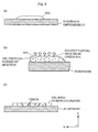
- Fig. 6 (a)-(c) illustrate a conventional process of forming electrolytic gels.
- a solution (gel) containing a proton conductive material is applied to a substrate, such as glass plate and teflon plate (a).
- the solvent vapors while condensation polymerization takes place in the sol (b), and an electrolytic gel membrane is formed (c) .
- the volume of the sol is reduced mainly at the surface due to the vaporization of the solvent. This puts an ununiform pressure on the electrolytic gel, causing a number of cracks in the electrolytic gel.
- These cracks formed in the electrolytic membrane would let pass increasing amounts of anode-gas and cathode-gas through and mix together during the operation of the fuel cell. This would reduce the generation efficiency of the fuel cell to a great extent.
- Japanese Laid-Open Patent Application Nos. H8-249923, H10-69817 and H11-203936 disclose methods for increasing the strength of the gel by adding organic materials. Yet, it is still difficult to make electrolytic layers as thin and uniform as is required for standard electrolytic layers being 10 ⁇ m to 100 ⁇ m thick. It is particularly difficult to produce such electrolytic layers of large size so as to fit for use in fuel cells of large size.
- an electrode a catalyst layer and a gas diffusion layer
- a channel plate for distributing a gas are arranged on each principal surface of an electrolytic layer.
- packings are provided in a space left between a principal surface of an electrolytic layer and a principal surface of a channel plate, surrounding their side surfaces, as illustrated by an enlarged view of a portion of a conventional unit cell (Fig. 13). These packings are provided to minimize the amount of gas escaping out of the cell.
- packings in some fuel cells are provided between a gas diffusion layer and a channel plate, as shown in Fig. 12 illustrating a sectional view of a portion of a unit cell.
- the present invention intends to provide a fuel cell that has an excellent electrolytic layer made of a proton conductive gel, and a manufacturing method thereof, so that the fuel cell can generate power with greater efficiency than conventional ones.
- a fuel cell unit having an electrolytic layer with a catalyst layer and a gas diffusion layer arranged on each principal surface in the stated order, characterized in that: the electrolytic layer is a porous sheet impregnated with an electrolytic gel, the electrolytic gel being gel particles made of a proton conductive material; and at least one of the catalyst layer and the gas diffusion layer has pores that are smaller than the electrolytic gel particles.
- a solvent of a solution containing a proton conductive material that is used for forming an electrolytic gel membrane permeates into and volatilize from either the catalyst layer or the gas diffusion layer.
- the electrolytic gel permeating into the catalyst layer or the gas diffusion layer does not fill the pores of the layers, nor float in the solution.
- the solvent accumulates on the catalyst layer or the gas diffusion layer instead, forming the electrolytic gel membrane. Therefore, the formed gel has a fine structure with a smaller number of cracks being formed.
- the formed electrolytic membrane With the electrolytic gel held in the porous sheet, the formed electrolytic membrane exhibits an excellent strength. Therefore, even a large-size electrolytic membrane does not suffer the formation of cracks.
- the proton conductive material may include (a) a material selected from the group consisting of SiO 2 , Al 2 O 3 , TiO 2 , V 2 O 5 and ZrO 2 , and (b) a material selected from the group consisting of phosphoric acid, perchloric acid, boric acid and silicic acid.
- a manufacturing method for forming an electrolytic gel for use in a fuel cell characterized in that: the electrolytic gel is formed by applying a solution containing a proton conductive material to a porous sheet.
- the porous sheet may have pores that are smaller than electrolytic gel particles.
- the solvent of the solution not only vaporizes from the surface of the solution, but also permeates into and vaporizes from the porous substrate. As the solvent vaporizes, the upward and downward forces that strain the electrolytic gel being formed in the solution are brought into balance, which helps lower the number of cracks formed in the gel.
- a manufacturing method for manufacturing a fuel cell unit including a lamination step for laminating a catalyst layer and a gas diffusion layer, and an electrolytic gel layer forming step for forming an electrolytic gel layer by applying a solution containing a proton conductive material to the catalyst layer, characterized in that: in the lamination step, at least one of the catalyst layer and the gas diffusion layer is made of a material that has smaller pores than the electrolytic gel particles; and in the electrolytic gel layer forming step, the catalyst layer and the gas diffusion layer are laminated in the stated order on a formed electrolytic gel layer, to manufacture a cell unit.
- a manufacturing method for manufacturing a fuel cell unit characterized in that: a porous sheet is inserted between two catalyst layers, and a gas diffusion layer is laminated on an outer surface of each catalyst layer, and the porous sheet is impregnated with a solution containing a proton conductive material, so that an electrolytic gel is grown and held in the porous sheet.
- a solvent of the solution in the porous sheet may permeate into and vapor from the gas diffusion layer, the gas diffusion layer being composed of a substrate impregnated with carbon powder.
- a fuel cell unit having an electrolytic layer that has a catalyst layer, a gas diffusion layer and a channel plate for distributing a gas laminated on each principal surface in the stated order, the fuel cell generating power when a fuel gas is distributed along one of the channel plates and an oxidizing gas is distributed along the other channel plate, characterized in that: the electrolytic layer contains a proton conductive gel; on at least one of the principal surfaces of the electrolytic layer, the catalyst layer and the gas diffusion layer are arranged so that their side surfaces are situated more inwardly than side surfaces of the electrolytic layer and the channel plates; and a seal member is applied to a side surface of the gas diffusion layer, or two or more seal members are applied to the side surfaces of the catalyst layers and the gas diffusion layers.
- the seal members applied in this way can substantially reduce the amount of gases escaping from the sides of the catalyst layers and the gas diffusion layers that are in contact with the seal members. This makes it more feasible to lower costs and generate power with greater efficiency.
- the seal member is made from a material that contains a proton conductive gel, the same material as used for the electrolytic membrane. Using this material increases the production efficiency, for the seal member and the electrolytic membrane can be formed at the same time.
- the seal member may be applied to at least specific side surfaces of the catalyst layers and the gas diffusion layers that are parallel to a pathway of the fuel gas in the channel plate.
- the seal members should preferably be provided on the side surfaces of both the catalyst layers and the gas diffusion layers in order to prevent a gas leakage with great efficiency.
- the proton conductive material may include (a) a material selected from the group consisting of SiO 2 , Al 2 O 3 , TiO 2 , V 2 O 5 and ZrO 2 , and (b) a material selected from the group consisting of phosphoric acid, perchloric acid, boric acid and silicic acid.
- the electrolytic layer may be a porous sheet impregnated with the proton conductive gel.
- the following describes a fuel cell, which is a first embodiment of the present invention.
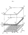
- Fig. 1 is an lamination drawing of a fuel cell (unit cell 1) of the first embodiment.
- the unit cell 1 is provided with a cathode-side channel plate 15 and an anode-side channel plate 16, with an electrolytic layer 10 sandwiched in between.
- the electrolytic layer 10 has a cathode-side catalyst layer 11 and a cathode-side gas diffusion layer 13 laminated on one surface, and an anode-side catalyst layer 12 and an anode-side gas diffusion layer 14 laminated on the other surface, in the stated order.
- construction elements 10-14 are combined into a lamination 2.
- the anode-side catalyst layer 12 and the cathode-side catalyst layer 11 are in the shape of a sheet and formed from a mixture of catalyst supporting powder (platinum supporting carbon powder) and PTFE.
- the gas diffusion layers 13 and 14 are formed by applying a water-repellent resin (tetrafluoroethylene hexafluoropropylene copolymer, FEP) to a substrate, which is 200 ⁇ m thick (carbon paper). This makes it water repellent. Carbon powder is then supplied to the resulting layers. This gives a higher liquid permeability to the gas diffusion layers 13 and 14 than conventional gas diffusion layers, which are made of carbon paper that has acquired water repellent property. As will be described later, the construction of the gas diffusion layers is determined so that a solvent of a proton conductive solution can permeate into and volatilize from the layers during an electrolytic layer-forming process.
- the gas diffusion layers 13 and 14 are also called collector layers, because they serve to ensure that electric currency pass through the catalyst layers 11-12 and the channel plates 15-16.
- a cathode is composed of the cathode-side catalyst layer 11 and the gas diffusion layer 13
- an anode is composed of the anode-side catalyst layer 12 and the gas diffusion layer 14.
- the anode-side channel plate 16 is formed by injection molding a mixture of carbon powder and a resinous material, such as phenol resin.
- Prallel ribs 166 are formed with some regular intervals on its surface facing the anode-side gas diffusion layer 14 (an undersurface in Fig. 1). They are arranged in the y direction, a direction orthogonal to x direction, when the x direction is a direction along the length.
- the intervals make channels 165 as a pathway for the anode gas (a purity hydrogen or a reformed gas containing ample hydrogen).
- the cathode-side channel plate 15 is almost the same as the anode-side channel plate 16. Though not illustrated in Fig. 1, the cathode-side channel plate 15 has ribs on the surface facing the cathode-side gas diffusion layer 13 with some regular intervals. The ribs are arranged in the x direction, a direction orthogonal to the y direction, when the y direction is a direction along the length of this fuel cell. The intervals make channels as a pathway for the cathode gas (an oxidizer such as air).
- an oxidizer such as air
- the electrolytic layer 10 is the characteristic element in this embodiment. It is formed of a ceramic porous sheet and a proton conductive gel impregnated therein.
- the proton conductive gel contains silicon oxide and Bronsted acid (phosphoric acid), with a high density of hydroxy group (OH-) chemically bonded with the silicon oxide on its end surface.
- the silicon oxide is supported by the Bronsted acid.
- the porous sheet is a non-woven fabric made of ceramic fibers .
- the proton conductive gel is filled in its pores for the sake of physical protection. Fewer cracks are formed during manufacturing process than those in conventional ones. Detailed explanation of the manufacturing method for the electrolytic layer 10 will be given later.
- the construction elements 10-16 have apertures (Fig. 1 illustrates apertures 131-134, 151-154, 161-163) at the.four corners of a principal surface, forming manifolds in the unit cell 1.
- the anode-gas comes through apertures 151, 131 and 161 and other apertures which are arranged in series, and proceeds in the z direction towards the channels 165.
- the anode-gas goes out from apertures 163, 133 and 153 and other apertures which are arranged in series in the z direction.
- the cathode-gas comes through the apertures 134 and 154 and other apertures which are arranged in series, and proceeds in the z direction towards the channels of the cathode-side channel plate 15.
- the cathode-gas goes out from apertures 162, 132 and 152 and other apertures which are arranged in series in the z direction.
- a plurality of cells 1 are stacked one against another, which are each sandwiched by a pair of partition plates. Both ends of the cell are fixed by means of a pair of end plates.
- Such a cell structure is called cell stack.
- a hydrogen gas (a reformed gas containing abundant hydrogen) as an anode gas and air as a cathode-gas are supplied.
- Hydrogen from the anode gas becomes a proton (H 2 ⁇ 2H + +2e - ) when it arrives in the vicinity of the anode, and moves through the gel in the electrolytic layer towards the cathode-side catalyst layer 11.
- the proton combines with oxygen from the cathode gas to form water (2H + +2e - +1/2O 2 ⁇ H 2 O). Having such a proton conductive gel in its porous sheet, the fuel cell can generate power even when there is little water left in the electrolytic layer 10.
- protons of hydroxy groups of silicon oxide or phosphoric acid do hop together with the few water molecules to pass electric current.
- Such fuel cells can operate even in a dry atmosphere or at a high temperature, because the hydroxy groups and the little amount of water rarely leave a surface of the electrolytic layer 10. This feature is unique to this type of fuel cells, and not detected in PEFCs such as Nafion made by DU PONT. PEFCs require a lot of water to assume proton conductivity.
- the electrolytic layer 10 in the first embodiment has a greater physical strength than conventional ones. This enables the unit cell 1 to continuously generate power in excellent condition, even when it is struck.
- the following describes a method for manufacturing the layers of the fuel cell.
- the gas diffusion layer is provided with so minute pores, about 10nm to 100nm wide, that particles of the proton conductive material solution cannot get through.
- a carbon paper impregnated with 16wt% of FEP is heated at 380°C for an hour to make it water repellent.
- a pasted mixture of carbon particles (having an average diameter of about 30mm) and PTFE is applied (at a ratio of 60wt% to 40wt%) to both surfaces of the carbon paper to fill the inside of the carbon paper.
- the carbon paper is then heated at 360°C for two hours.
- the resulting gas diffusion layer has minute pores of about 10nm to 100nm in diameter.
- the gas diffusion layer may also be formed by mixing carbon particles and fluororesins such as PTFE with a ratio of 70wt% to 30wt%, and by rolling the mixture into a sheet-like form of about 100 ⁇ m thick.
- the catalyst layer (an electrode) is formed by mixing platinum supporting carbon powder with PTFE with a ratio of 70wt% to 30wt%.
- the catalyst layer is 20 ⁇ m thick and in the shape of a sheet.
- the following describes how to make a solution of a proton conductive material, which is used in forming the electrolytic layer.
- the following describes how to make the electrolytic layer and assemble the unit cell using the solution of proton conductive material.
- the gas diffusion layers and catalyst layers are hot pressed (150°C, 20kgf/cm2, 10sec) and combined into two laminations. It is required to set the size of the laminations beforehand so that one of them has a larger area than the other.
- the two laminations are set at their places so that their catalyst layers face with each other.
- a porous sheet 50 ⁇ m thick, is inserted between the laminations which makes a frame of the electrolytic layer.
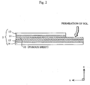
- the thickness of the porous sheet may vary from 10 ⁇ m to 100 ⁇ m, but the porous sheet should be of the same size as the larger lamination. Then, they are put together so that an end of the porous sheet is beyond those of the laminations, as shown in a partial cross sectional view of Fig. 2.
- the porous sheet is made from a non-electronic conductive material selected from the group consisting of glass, ceramic and resin. More preferably, the porous sheet should be made from a proton conductive material (e.g. a compound of silicon oxide containing phosphoric acid), as in the case of an electrolytic gel.
- a proton conductive material e.g. a compound of silicon oxide containing phosphoric acid
- an electrolytic gel membrane is formed by sol-gel method.
- the solution of a proton conductive material (sol) is applied to the porous sheet.
- the solvent permeates into the porous sheet and evaporates from the porous sheet and then from gas diffusion layer.
- the sol-gel method takes advantage of the condensation polymerization that occurs in the solution between silicon oxide and every alkoxide of phosphoric acid.
- the resulting proton conductive gel in a solid form, has a plurality of minute pores (of an order of a few nm). Hydroxy groups are connected to the surface of the minute pores, which enable the formed gel to offer excellent proton conductivity.
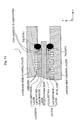
- Fig. 3 is a sectional view of a substrate illustrating how the electrolytic gel membrane grows in the porous sheet.
- the solvent of the sol permeates into the catalyst layer, and then into the gas diffusion layer due to capillary attraction.
- the solvent permeates especially smoothly into the gas diffusion layer, because it is filled with carbon powder.
- the permeation of the solvent brings about condensation polymerization at the interface between the sol and the catalyst layers on both principal surfaces of the porous sheet. This expedites the growth of the electrolytic gel membrane.
- the solvent permeates into some portion where no electrolytic gel membrane is formed and accumulated.
- the permeation and volatilization of the solvent take place uniformly both at the sol and the substrate (upwardly and downwardly as shown in Fig. 3). This means that a sol comes under a uniform tension when volume shrinkage occurs. Having such a compact structure, the resulting electrolytic gel membrane is less tending to the formation of cracks.
- the pores in the gas diffusion layer are so small, 10-100nm in diameter, that the gel does not permeate into the gas diffusion layer but stays inside the porous sheet. This makes it possible to form an excellent electrolytic gel membrane, without the gas diffusion property of the layer being destroyed.
- the resulting electrolytic gel is aired for a predetermined period of time at room temperature, and provided in the form of layers.
- the porous sheet for the electrolytic layer is not an essential component in the present invention.
- an electrolytic gel membrane can be formed by applying a sol (a) containing a proton conductive material to a porous substrate (that has a greater number of minute pores, 10-100nm, than those of the porous sheet), so that a solvent vapors from both of the surfaces of the sol (a) at the same rate.
- a resulting electrolytic gel membrane there are fewer numbers of cracks than in conventional ones. Even when this electrolytic gel membrane is removed from the substrate and used separately as an electrolytic layer, the same effect of the present invention can be obtained (or rather, it can offer greater generation efficiency).
- the gel is more easily broken than the porous sheet, it is preferable here to use a lamination of a gas diffusion layer filled with carbon powder and a catalyst layer, instead of the porous substrate, and form an electrolytic gel membrane on the catalyst layer. This saves the need to remove the electrolytic gel from the substrate.
- the production yield can be improved by putting a pair of laminations consisting of an electrolytic gel, gas diffusion layer and catalyst layer, together so that the electrolytic gels come in face to face.
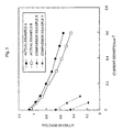
- the actual examples A and B exhibited greater generation efficiency than the comparison examples X and Y.
- the electrolytic layer of the present invention which is formed by applying an electrolytic gel to a permeable porous sheet, can offer greater generation efficiency than conventional membranes.
- the porous sheet used for this actual example A was made of silica gel containing a proton conductive material, namely phosphoric acid, and that this material made it possible for the actual example A to maintain excellent proton conductivity.
- the comparison example X showed a low voltage. Assumingly, this is because a plurality of cracks formed in the electrolytic gel membrane allowed the cathode-gas and anode-gas to pass through and mix with during the operation, having led to a reduction in generation efficiency.
- the low cell voltage of the comparison example Y can be attributed to the use of gas diffusion layer that has no carbon powder filled in. Since the pores in the gas diffusion layer were larger in size than they are supposed to be, the gel passed through the pores while an electrolytic layer gel was being formed. This must have disrupted the gas diffusion property of the comparison example Y.
- an electrolytic gel is formed with a proton-conductive solvent permeating into and vaporing from a gas diffusion layer.
- the application of the present invention is not limited to such.
- the permeation and volatilization of the solvent may be performed on a catalyst layer.
- the catalyst layers 11 and 12 have minute pores, 10-100nm wide, as shown in the sectional view of Fig. 3, and the catalyst layers are as thick as 50 ⁇ m.
- catalyst layers have small pores, 2-3 ⁇ m to 20-30 ⁇ m in diameter, but they are not so small as to block the passage of an electrolytic gel.
- the electrolytic gel in the second embodiment can produce the same effect as in the first embodiment, in which the gas diffusion layers 13 and 14 are used.
- a compound of silicon oxide that contains phosphoric acid is cited as an example of a proton conductive material.
- other compounds of silicon oxide may be used for this purpose if a compound capable of providing protons, such as phosphoric acid, perchloric acid, boric acid and silicic acid, is included in them.
- compounds that are proton conductive such as Al 2 O 3 , TiO 2 , V 2 O 5 and ZrO 2 , can be used instead of silicon oxide.
- the gas diffusion layer is filled with carbon powder so that minute pores are formed in it.
- carbon powder fine powder, including fine powder of metal, glass and ceramics can be used to produce the same effects. Nevertheless, it is the most preferable to use carbon powder, because carbon powder offers good electron conductivity and resistance to erosion, and is easy to set the particle diameter.
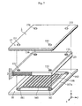
- Fig. 7 is an assembly drawing of a fuel cell (including a view of a seal member 20 of a unit cell 2, with a portion broken away) in the third embodiment.
- the unit cell 1 is provided with a cathode-side channel plate 15 and an anode-side channel plate 16, with an electrolytic layer 10 sandwiched in between.
- the electrolytic layer 10 has a cathode-side catalyst layer 11 and a cathode-side gas diffusion layer 13 laminated on one surface, and an anode-side catalyst layer 12 and an anode-side gas diffusion layer 14 laminated on the other surface, in the stated order.
- construction elements 10-14 are combined into a lamination 2.
- the sizes of the principal surfaces of the construction elements 10-14 are predetermined as being almost the same.
- the anode-side catalyst layer 12 and the cathode-side catalyst layer 11 are in the shape of a sheet and formed from a mixture of catalyst supporting powder (platinum supporting carbon powder) and PTFE.
- the gas diffusion layers 13 and 14 are formed by applying a water-repellent resin (tetrafluoroethylene hexafluoropropylene copolymer, FEP) to a substrate, which is 200 ⁇ m thick (carbon paper). This makes it water repellent.
- a water-repellent resin tetrafluoroethylene hexafluoropropylene copolymer, FEP
- the gas diffusion layers 13 and 14 are also called collector layers, because they serve to ensure that electric currency pass through the catalyst layers 11-12 and the channel plates 15-16.
- a cathode is defined as being composed of the cathode-side catalyst layer 11 and the gas diffusion layer 13, and an anode as being composed of the anode-side catalyst layer 12 and the gas diffusion layer 14, to which the present embodiment comply with as well.
- the anode-side channel plate 16 is formed by injection molding a mixture of carbon powder and a resinous material, such as phenol resin.
- Prallel ribs 166 are formed with some regular intervals on its surface facing the anode-side gas diffusion layer 14. They are arranged in the y direction, a direction orthogonal to x direction, when the x direction is a direction along the length. The intervals make channels 165 as a pathway for the anode gas (a purity hydrogen or a reformed gas containing ample hydrogen).
- the cathode-side channel plate 15 is almost the same as the anode-side channel plate 16. Though not illustrated in Fig. 1, the cathode-side channel plate 15 has ribs on the surface facing the cathode-side gas diffusion layer 13 with some regular intervals. The ribs are arranged in the x direction, a direction orthogonal to the y direction, when the y direction is a direction along the length of this fuel cell. The intervals make channels as a pathway for the cathode gas (an oxidizer such as air).
- an oxidizer such as air
- the channel plates 15 and 16 are larger in size in the x and y directions than the lamination 2, so that their sides are situated more outwardly than the sides of the lamination 2.
- the electrolytic layer 10 is formed of a ceramic porous sheet and a proton conductive gel impregnated therein.
- the proton conductive gel contains silicon oxide and Bronsted acid (phosphoric acid), with a high density of hydroxy group (OH-) chemically bonded with the silicon oxide on its end surface.
- the silicon oxide is supported by the Bronsted acid.
- the porous sheet is a non-woven fabric made of ceramic fibers .
- the proton conductive gel is filled in its pores for the sake of physical protection. With this construction, fewer cracks are formed during manufacturing process than those in conventional ones. It does not matter whether this porous sheet is included or not, but the porous sheet should preferably be provided to strengthen the proton conductive gel.
- the seal member 20 is situated so as to cover the side surfaces of the lamination 2, which is characteristic of the third embodiment. About the seal member 20, a detailed explanation will be given later.
- the construction elements 10-16 have apertures (Fig. 1 illustrates apertures 131-134, 151-154, 161-163) at the four corners of a principal surface, forming manifolds in the unit cell 1.
- the anode-gas fuel gas comes through apertures 151, 131 and 161 and other apertures which are arranged in series, and proceeds in the z direction towards the channels 165.
- the anode-gas goes out from apertures 163, 133 and 153 and other apertures which are arranged in series in the z direction.
- the cathode-gas oxidizing gas comes through the apertures 134 and 154 and other apertures which are arranged in series, and proceeds in the z direction towards the channels of the cathode-side channel plate 15.
- the cathode-gas goes out from apertures 162, 132 and 152 and other apertures which are arranged in series in the z direction.
- An elastic rubber packing 167a (157a, in Fig. 8) is provided between the cathode-side channel plate 15 (anode-side channel plate 16) and the lamination 2 so as to surround the sides of the principal surface.
- a plurality of cells 1 are stacked one against another, which are each sandwiched by a pair of partition plates. Both ends of the cell are fixed by means of a pair of end plates.
- Such a cell structure is called cell stack. It is preferable that in such a cell stack, the packings 167a and 157a are arranged on the both surfaces of the cathode-side channel plate 15 (anode-side channel plate 16) so that gas does not leak from the space between two adjacent unit cells 1.
- a hydrogen gas (a reformed gas containing abundant hydrogen) as an anode gas and air as a cathode-gas are supplied.
- Hydrogen from the anode gas becomes a proton (H 2 ⁇ 2H + +2e - ) when it arrives in the vicinity of the anode, and moves through the gel in the electrolytic layer towards the cathode-side catalyst layer 11.
- the proton combines with oxygen from the cathode gas to form water (2H + +2e - +1/2O 2 ⁇ H 2 O). Having such a proton conductive gel in its porous sheet, the fuel cell can generate power even when there is little water left in the electrolytic layer 10.
- protons of hydroxy groups of silicon oxide or phosphoric acid do hop together with the few water molecules to pass electric current.
- Such fuel cells can operate even in a dry atmosphere or at a high temperature, because the hydroxy groups and the little amount of water rarely leave a surface of the electrolytic layer 10. This feature is unique to this type of fuel cells, and not detected in PEFCs such as Nafion made by DU PONT. PEFCs require a lot of water to assume proton conductivity.
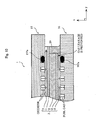
- Fig. 8 is a sectional view, taken along the plane yz , of the lamination 2.
- seal members 20, which are the characteristic component of the third embodiment, are provided in a unit cell 1 so that it is in contact with the inner surface of the channel plate 15 and cover the side surfaces of the lamination 2.
- the side surfaces of the catalyst layers 11-12 and gas diffusion layers 13-14 are not exposed to air, which makes the lamination 2 a gastight compartment.
- the seal member 20 is made from a proton conductive gel, the same material as that used for the electrolytic layer 10. After the channel plates 15-16 are set in a position to sandwich the lamination 2, the proton conductive gel is applied to the side surfaces of the lamination 2 and it is cured.
- seal members 20 prevent the gases flowing through the manifolds from escaping out of the openings at the side of the lamination 2.
- a typical fuel unit cell has an electrolytic layer with electrodes (catalyst layers and gas diffusion layers) and channel plates for distributing gases on each principal surface.
- electrodes catalyst layers and gas diffusion layers
- channel plates for distributing gases on each principal surface.
- packings are provided between a principal surface of an electrolytic layer and a principal surface of a channel plate, as shown in a sectional view illustrating a portion of conventional layers (Fig. 13). This is aimed at minimizing the leakage of a supplied gas.
- packings are arranged between a gas diffusion layer and a channel plate in some fuel cells, as shown in Fig. 12 illustrating a sectional view of a portion of a unit cell.
- the fuel cell in the third embodiment has seal members 20 at the side surfaces of the lamination 2, which is composed of the electrolytic layer 10, catalyst layers 11 and 12, and the gas diffusion layers 13 and 14. All of the lamination components are of the same size.
- the seal members 20 are made of proton conductive gel, the same material as that for the electrolytic layer 10. This incredibly gastight material is provided in contact with the gas permeable catalyst layers and gas diffusion layers, as shown in the sectional view of a fuel cell in Fig. 9. This helps prevent a gas leakage effectively and improve the efficiency of power generation.
- the seal members 20 prevent leakage of the anode-gas and cathode-gas. Unless a cathode-gas (oxidizer) leakage causes a major problem, which may occur when the cathode-gas is air, the seal member 20 may be provided at the side surfaces of the anode-side catalyst layer 12 and the anode-side gas diffusion layer 14.
- the following describes a method for manufacturing the layers of the unit cell.
- the gas diffusion layer is provided with so minute pores, about 10nm to 100nm wide, that particles of the proton conductive material solution cannot get through.
- a carbon paper impregnated with 16wt% of FEP is heated at 380°C for an hour to make it water repellent.
- a pasted mixture of carbon particles (having an average diameter of about 30mm) and PTFE is applied (at a ratio of 60wt% to 40wt%) to both surfaces of the carbon paper to fill the inside of the carbon paper.
- the carbon paper is then heated at 360°C for two hours.
- the resulting gas diffusion layer has minute pores of about 10nm to 100nm in diameter.
- the gas diffusion layer may also be formed by mixing carbon particles and fluororesins such as PTFE with a ratio of 70wt% to 30wt%, and by rolling the mixture into a sheet-like form of about 100 ⁇ m thick.
- the catalyst layer (an electrode) is formed by mixing platinum supporting carbon powder with PTFE, with a ratio of 70wt% to 30wt%, into a sheet of a thickness of 20 ⁇ m.
- the following describes how to make a solution of a proton conductive material, which is used in forming the electrolytic layer.
- the following describes how to make the electrolytic layer and assemble the unit cell using the solution of proton conductive material.
- the gas diffusion layers and catalyst layers are hot pressed (150°C, 20kgf/cm2, 10sec) and combined into two laminations. It is required to set the size of the laminations beforehand so that one of them has a larger area than the other.
- a porous sheet 50 ⁇ m thick, is inserted between the laminations which makes a frame of the electrolytic layer.
- the thickness of the porous sheet may vary from 10 ⁇ m to 100 ⁇ m.
- the porous sheet is made from a non-electronic conductive material selected from the group consisting of glass, ceramic and resin. More preferably, the porous sheet should be made from a proton conductive material (e.g. a compound of silicon oxide containing phosphoric acid), as in the case of an electrolytic gel.
- a proton conductive material e.g. a compound of silicon oxide containing phosphoric acid
- the solution of a proton conductive material is applied to the porous sheet.
- the solvent permeates into the porous sheet and evaporates from the porous sheet and then from gas diffusion layer.
- the condensation polymerization occurs in the solution between silicon oxide and every alkoxide of phosphoric acid.
- the resulting proton conductive gel in a solid form, has a plurality of minute pores (of an order of a few nm). Hydroxy groups are connected to the surface of the minute pores, which enable the formed gel to offer excellent proton conductivity.
- the formed lamination 2 is sandwiched between the two channel plates 15 and 16.
- the solution of 1-c is applied to (and filled in) the side surface of the lamination 2, dried and formed into the seal member 20. It is preferable to determine the amount of the solution so that the complete seal member 20 has the same thickness as the gas diffusion layer (which is about 0.2mm).
- the method of forming the seal member 20 is not limited to the above method.
- the seal member 20 may be formed on a side of the lamination 2 before the lamination 2 is sandwiched between the channel plates 15 and 16.
- the actual example A exhibited greater generation efficiency than the comparison example X. This shows that the use of the seal member 20 increased an efficiency at which a gas is used, and that power is generated with great efficiency.
- a compound of silicon oxide that contains phosphoric acid is cited as an example of a proton conductive material.
- other compounds of silicon oxide may be used for this purpose if a compound capable of providing protons, such as phosphoric acid, perchloric acid, boric acid and silicic acid, is included in them.
- compounds that are proton conductive such as Al 2 O 3 , TiO 2 , V 2 O 5 and ZrO 2 , can be used instead of silicon oxide.
- the seal members 20 are provided on the side surfaces of the anode-side and cathode-side gas diffusion layers. But the seal member 20 may be attached to either one of the gas diffusion layers. For instance, if the seal member 20 is positioned at an end portion of the anode-side gas diffusion layer, the efficiency of using H 2 gas can be increased and the cost can be reduced.
- a seal member 20 is provided so as to surround the lamination 2, but the same effect can be obtained if the seal member 20 is attached to the side surfaces that are parallel to the gas pathway.
- the seal member 20 can be made from materials other than the proton conductive gel.
- the seal member 20 may be formed from gas-tight materials, such as resinous materials, glass and ceramics.
- seal member 20 prevents a gas leakage effectively, it is no longer necessary to provide the packings 157a and 167a in the present invention. The positioning of those packings can be changed.
- the present invention is applicable to electrolytic layers for use in fuel cells.
Landscapes
- Life Sciences & Earth Sciences (AREA)
- Engineering & Computer Science (AREA)
- Manufacturing & Machinery (AREA)
- Sustainable Development (AREA)
- Sustainable Energy (AREA)
- Chemical & Material Sciences (AREA)
- Chemical Kinetics & Catalysis (AREA)
- Electrochemistry (AREA)
- General Chemical & Material Sciences (AREA)
- Fuel Cell (AREA)
Abstract
A fuel cell unit having an electrolytic layer with a
catalyst layer and a gas diffusion layer arranged in the stated
order on each principal surface is provided. The electrolytic
layer is composed of a porous sheet and an electrolytic gel
impregnated therein. The electrolytic gel is gel particles
made of a proton conductive material. At least one of the
catalyst layer and the gas diffusion layer has pores that are
smaller than the electrolytic gel particles.
Description
The present invention relates to a fuel cell unit and a
manufacturing method thereof.
Fuel cells have a unit construction in which an
electrolytic layer is sandwiched between anode-side catalyst
layers and cathode-side catalyst layers, which are sandwiched
between two gas diffusion layers. When an anode gas containing
hydrogen is supplied at the anode side and a cathode gas
containing oxygen is (oxidizing gas) supplied at the cathode
side, these hydrogen and oxygen are combined together to
generate power. As a cathode gas, air is commonly used, while
as an anode gas, a reformed gas containing ample hydrogen or
a purity hydrogen gas is used. The reformed gases are formed
by reforming fuel gases, such as natural gas, naphtha and other
light carbon hydrogen, using fuel gas reformers (reformers, CO
transformers and CO removers).
Among a variety of electrolytic layers used in fuel
cells, solid polymer fuel cells, whose electrolytic layer is
a solid polymer membrane made of cation exchange resin, are most
widely used as a power source for vehicles, cellular phones and
other outdoor equipment.
In recent years, there has been a research on the use of
a proton conductive gel as an electrolytic layer for fuel cells.
Japanese Laid-Open Patent Applications Nos. H8-249923 and
H11-203936 teach that this proton conductive gel is a compound
primarily composed of silicon oxide and Bronsted acid
(principally phosphoric acid) and is made by a sol-gel
transformation method. Fuel cells having such a proton
conductive gel electrolytic layer can generate power at higher
operating temperatures (150°C)than polymer electrolytic layer
fuel cells or PEFCs (about 100 °C ) . Therefore, unlike
conventional PEFCs, there is no need to cool down a hot reformed
gas that has been generated by means of fuel cell reformers to
a moderate operating temperature of a fuel cell (around 100°C).
This is a great improvement in terms of power generation
efficiency. In PEFCs, solid polymer films must be kept moist,
in case the internal resistance should increase and the
generation efficiency should drop accordingly. In contrast,
since the proton conductive gel requires lesser amount of water
for power generation than solid polymer films, a fuel cell of
this type can stably generate power even at higher temperatures
than PEFCs.
It is expected that most of the problems associated with
PEFCs can be solved by employing such proton conductive gel as
electrolytic layers.
However, there are several problems to be solved before
using this proton conductive gel to produce superior
electrolytic layers (membranes).
Fig. 6 (a)-(c) illustrate a conventional process of
forming electrolytic gels. As shown herein, a solution (gel)
containing a proton conductive material is applied to a
substrate, such as glass plate and teflon plate (a). The
solvent vapors while condensation polymerization takes place
in the sol (b), and an electrolytic gel membrane is formed (c) .
However, during the processes (b) and (c), the volume of the
sol is reduced mainly at the surface due to the vaporization
of the solvent. This puts an ununiform pressure on the
electrolytic gel, causing a number of cracks in the electrolytic
gel. These cracks formed in the electrolytic membrane would
let pass increasing amounts of anode-gas and cathode-gas
through and mix together during the operation of the fuel cell.
This would reduce the generation efficiency of the fuel cell
to a great extent.
In an attempt to solve the problems, Japanese Laid-Open
Patent Application Nos. H8-249923, H10-69817 and H11-203936
disclose methods for increasing the strength of the gel by
adding organic materials. Yet, it is still difficult to make
electrolytic layers as thin and uniform as is required for
standard electrolytic layers being 10 µm to 100 µm thick. It
is particularly difficult to produce such electrolytic layers
of large size so as to fit for use in fuel cells of large size.
In typical fuel cells, an electrode (a catalyst layer and
a gas diffusion layer) and a channel plate for distributing a
gas are arranged on each principal surface of an electrolytic
layer. In the case of conventional PEFC units, packings are
provided in a space left between a principal surface of an
electrolytic layer and a principal surface of a channel plate,
surrounding their side surfaces, as illustrated by an enlarged
view of a portion of a conventional unit cell (Fig. 13). These
packings are provided to minimize the amount of gas escaping
out of the cell.
Attaching such packings to the electrolytic layer made
of the proton conductive gel, however, involves a risk that the
vitreous membrane may be broken. To avoid the damage on the
membrane, packings in some fuel cells are provided between a
gas diffusion layer and a channel plate, as shown in Fig. 12
illustrating a sectional view of a portion of a unit cell.
Certainly, pressure put on the electrolytic layer is lowered
with this arrangement, but this causes another problem that a
gas escapes from the sides of the gas diffusion layers and the
cathode beds (at both the cathode-side and anode-side). This
problem has a serious impact on its efficiency and cost, and
therefore needs to be solved quickly.
In view of the above problems, the present invention
intends to provide a fuel cell that has an excellent
electrolytic layer made of a proton conductive gel, and a
manufacturing method thereof, so that the fuel cell can generate
power with greater efficiency than conventional ones.
It is another object of the present invention to provide
a fuel cell that has an excellent electrolytic layer made of
a proton conductive gel, and a manufacturing method thereof,
so that the fuel cell can prevent a possible gas leakage and
generate power with greater efficiency than conventional ones.
The above objects are fulfilled by a fuel cell unit having
an electrolytic layer with a catalyst layer and a gas diffusion
layer arranged on each principal surface in the stated order,
characterized in that: the electrolytic layer is a porous sheet
impregnated with an electrolytic gel, the electrolytic gel
being gel particles made of a proton conductive material; and
at least one of the catalyst layer and the gas diffusion layer
has pores that are smaller than the electrolytic gel particles.
When at least one of the catalyst layer and the gas
diffusion layer has the stated construction, a solvent of a
solution containing a proton conductive material that is used
for forming an electrolytic gel membrane permeates into and
volatilize from either the catalyst layer or the gas diffusion
layer. The electrolytic gel permeating into the catalyst layer
or the gas diffusion layer does not fill the pores of the layers,
nor float in the solution. The solvent accumulates on the
catalyst layer or the gas diffusion layer instead, forming the
electrolytic gel membrane. Therefore, the formed gel has a fine
structure with a smaller number of cracks being formed.
With the electrolytic gel held in the porous sheet, the
formed electrolytic membrane exhibits an excellent strength.
Therefore, even a large-size electrolytic membrane does not
suffer the formation of cracks.
In the above fuel cell unit, the proton conductive
material may include (a) a material selected from the group
consisting of SiO2, Al2O3, TiO2, V2O5 and ZrO2, and (b) a material
selected from the group consisting of phosphoric acid,
perchloric acid, boric acid and silicic acid.
The above objects are also fulfilled by a manufacturing
method for forming an electrolytic gel for use in a fuel cell,
characterized in that: the electrolytic gel is formed by
applying a solution containing a proton conductive material to
a porous sheet.
In the above manufacturing method, the porous sheet may
have pores that are smaller than electrolytic gel particles.
With this method, the solvent of the solution not only
vaporizes from the surface of the solution, but also permeates
into and vaporizes from the porous substrate. As the solvent
vaporizes, the upward and downward forces that strain the
electrolytic gel being formed in the solution are brought into
balance, which helps lower the number of cracks formed in the
gel.
The above objects are also fulfilled by a manufacturing
method for manufacturing a fuel cell unit including a lamination
step for laminating a catalyst layer and a gas diffusion layer,
and an electrolytic gel layer forming step for forming an
electrolytic gel layer by applying a solution containing a
proton conductive material to the catalyst layer, characterized
in that: in the lamination step, at least one of the catalyst
layer and the gas diffusion layer is made of a material that
has smaller pores than the electrolytic gel particles; and in
the electrolytic gel layer forming step, the catalyst layer and
the gas diffusion layer are laminated in the stated order on
a formed electrolytic gel layer, to manufacture a cell unit.
The same effects can be achieved by using this method as
when using the above manufacturing method for manufacturing the
electrolytic gel. Also, when the catalyst layer and the gas
diffusion layer are used as a porous substrate, it becomes
possible to manufacture a fuel cell unit soon after an
electrolytic gel is grown. This increases the yield in
producing fuel cell units.
The above objects are also fulfilled by a manufacturing
method for manufacturing a fuel cell unit, characterized in
that: a porous sheet is inserted between two catalyst layers,
and a gas diffusion layer is laminated on an outer surface of
each catalyst layer, and the porous sheet is impregnated with
a solution containing a proton conductive material, so that an
electrolytic gel is grown and held in the porous sheet.
In the above manufacturing method, a solvent of the
solution in the porous sheet may permeate into and vapor from
the gas diffusion layer, the gas diffusion layer being composed
of a substrate impregnated with carbon powder.
The above objects are also fulfilled by a fuel cell unit
having an electrolytic layer that has a catalyst layer, a gas
diffusion layer and a channel plate for distributing a gas
laminated on each principal surface in the stated order, the
fuel cell generating power when a fuel gas is distributed along
one of the channel plates and an oxidizing gas is distributed
along the other channel plate, characterized in that: the
electrolytic layer contains a proton conductive gel; on at least
one of the principal surfaces of the electrolytic layer, the
catalyst layer and the gas diffusion layer are arranged so that
their side surfaces are situated more inwardly than side
surfaces of the electrolytic layer and the channel plates; and
a seal member is applied to a side surface of the gas diffusion
layer, or two or more seal members are applied to the side
surfaces of the catalyst layers and the gas diffusion layers.
The seal members applied in this way can substantially
reduce the amount of gases escaping from the sides of the
catalyst layers and the gas diffusion layers that are in contact
with the seal members. This makes it more feasible to lower
costs and generate power with greater efficiency.
The seal member is made from a material that contains a
proton conductive gel, the same material as used for the
electrolytic membrane. Using this material increases the
production efficiency, for the seal member and the electrolytic
membrane can be formed at the same time.
In the above fuel cell unit, the seal member may be applied
to at least specific side surfaces of the catalyst layers and
the gas diffusion layers that are parallel to a pathway of the
fuel gas in the channel plate.
This is shown by experiments conducted by inventors of
the present application. The seal members should preferably
be provided on the side surfaces of both the catalyst layers
and the gas diffusion layers in order to prevent a gas leakage
with great efficiency.
In the above fuel cell units, the proton conductive
material may include (a) a material selected from the group
consisting of SiO2, Al2O3, TiO2, V2O5 and ZrO2, and (b) a material
selected from the group consisting of phosphoric acid,
perchloric acid, boric acid and silicic acid.
In the above fuel cell units, the electrolytic layer may
be a porous sheet impregnated with the proton conductive gel.
The following describes a fuel cell, which is a first
embodiment of the present invention.
Fig. 1 is an lamination drawing of a fuel cell (unit cell
1) of the first embodiment. The unit cell 1 is provided with
a cathode-side channel plate 15 and an anode-side channel plate
16, with an electrolytic layer 10 sandwiched in between. The
electrolytic layer 10 has a cathode-side catalyst layer 11 and
a cathode-side gas diffusion layer 13 laminated on one surface,
and an anode-side catalyst layer 12 and an anode-side gas
diffusion layer 14 laminated on the other surface, in the stated
order. Of these, construction elements 10-14 are combined into
a lamination 2.
The anode-side catalyst layer 12 and the cathode-side
catalyst layer 11 are in the shape of a sheet and formed from
a mixture of catalyst supporting powder (platinum supporting
carbon powder) and PTFE.
The gas diffusion layers 13 and 14 are formed by applying
a water-repellent resin (tetrafluoroethylene
hexafluoropropylene copolymer, FEP) to a substrate, which is
200 µm thick (carbon paper). This makes it water repellent.
Carbon powder is then supplied to the resulting layers. This
gives a higher liquid permeability to the gas diffusion layers
13 and 14 than conventional gas diffusion layers, which are made
of carbon paper that has acquired water repellent property. As
will be described later, the construction of the gas diffusion
layers is determined so that a solvent of a proton conductive
solution can permeate into and volatilize from the layers during
an electrolytic layer-forming process. The gas diffusion
layers 13 and 14 are also called collector layers, because they
serve to ensure that electric currency pass through the catalyst
layers 11-12 and the channel plates 15-16.
Note that a cathode is composed of the cathode-side catalyst
layer 11 and the gas diffusion layer 13, and an anode is composed
of the anode-side catalyst layer 12 and the gas diffusion layer
14.
The anode-side channel plate 16 is formed by injection
molding a mixture of carbon powder and a resinous material, such
as phenol resin. Prallel ribs 166 are formed with some regular
intervals on its surface facing the anode-side gas diffusion
layer 14 (an undersurface in Fig. 1). They are arranged in the
y direction, a direction orthogonal to x direction, when the
x direction is a direction along the length. The intervals make
channels 165 as a pathway for the anode gas (a purity hydrogen
or a reformed gas containing ample hydrogen).
The cathode-side channel plate 15 is almost the same as the
anode-side channel plate 16. Though not illustrated in Fig.
1, the cathode-side channel plate 15 has ribs on the surface
facing the cathode-side gas diffusion layer 13 with some regular
intervals. The ribs are arranged in the x direction, a
direction orthogonal to the y direction, when the y direction
is a direction along the length of this fuel cell. The intervals
make channels as a pathway for the cathode gas (an oxidizer such
as air).
The electrolytic layer 10 is the characteristic element in
this embodiment. It is formed of a ceramic porous sheet and
a proton conductive gel impregnated therein. The proton
conductive gel contains silicon oxide and Bronsted acid
(phosphoric acid), with a high density of hydroxy group (OH-)
chemically bonded with the silicon oxide on its end surface.
The silicon oxide is supported by the Bronsted acid.
The porous sheet is a non-woven fabric made of ceramic fibers .
The proton conductive gel is filled in its pores for the sake
of physical protection. Fewer cracks are formed during
manufacturing process than those in conventional ones.
Detailed explanation of the manufacturing method for the
electrolytic layer 10 will be given later.
The construction elements 10-16 have apertures (Fig. 1
illustrates apertures 131-134, 151-154, 161-163) at the.four
corners of a principal surface, forming manifolds in the unit
cell 1. The anode-gas comes through apertures 151, 131 and 161
and other apertures which are arranged in series, and proceeds
in the z direction towards the channels 165. The anode-gas goes
out from apertures 163, 133 and 153 and other apertures which
are arranged in series in the z direction. Similarly, the
cathode-gas comes through the apertures 134 and 154 and other
apertures which are arranged in series, and proceeds in the z
direction towards the channels of the cathode-side channel
plate 15. The cathode-gas goes out from apertures 162, 132 and
152 and other apertures which are arranged in series in the z
direction.
To ensure high power generation, a plurality of cells 1 are
stacked one against another, which are each sandwiched by a pair
of partition plates. Both ends of the cell are fixed by means
of a pair of end plates. Such a cell structure is called cell
stack.
During the operation of the fuel cell, a hydrogen gas (a
reformed gas containing abundant hydrogen) as an anode gas and
air as a cathode-gas are supplied. Hydrogen from the anode gas
becomes a proton (H2→2H++2e-) when it arrives in the vicinity
of the anode, and moves through the gel in the electrolytic layer
towards the cathode-side catalyst layer 11. The proton
combines with oxygen from the cathode gas to form water
(2H++2e-+1/2O2→H2O). Having such a proton conductive gel in its
porous sheet, the fuel cell can generate power even when there
is little water left in the electrolytic layer 10. In the
proton conductive gel, protons of hydroxy groups of silicon
oxide or phosphoric acid do hop together with the few water
molecules to pass electric current. Such fuel cells can operate
even in a dry atmosphere or at a high temperature, because the
hydroxy groups and the little amount of water rarely leave a
surface of the electrolytic layer 10. This feature is unique
to this type of fuel cells, and not detected in PEFCs such as
Nafion made by DU PONT. PEFCs require a lot of water to assume
proton conductivity.
Formed of the porous sheet and the electrolytic gel
impregnated therein, the electrolytic layer 10 in the first
embodiment has a greater physical strength than conventional
ones. This enables the unit cell 1 to continuously generate
power in excellent condition, even when it is struck.
Compared with conventional electrolytic layers, there
are fewer cracks formed in the electrolytic layer 10. This
alleviates the problem of the anode-gas and cathode-gas getting
through the cracks and being mixed during the operation. This
improves the generation efficiency of the fuel cell.
The following describes a method for manufacturing the
layers of the fuel cell.
In the present invention, it is necessary that a solvent
of the proton conductive gel should permeate into and vapor from
the gas diffusion layer. For this purpose, the gas diffusion
layer is provided with so minute pores, about 10nm to 100nm wide,
that particles of the proton conductive material solution
cannot get through.
Firstly, a carbon paper impregnated with 16wt% of FEP is
heated at 380°C for an hour to make it water repellent. A pasted
mixture of carbon particles (having an average diameter of about
30mm) and PTFE is applied (at a ratio of 60wt% to 40wt%) to both
surfaces of the carbon paper to fill the inside of the carbon
paper. The carbon paper is then heated at 360°C for two hours.
As a result, the resulting gas diffusion layer has minute pores
of about 10nm to 100nm in diameter.
The gas diffusion layer may also be formed by mixing carbon
particles and fluororesins such as PTFE with a ratio of 70wt%
to 30wt%, and by rolling the mixture into a sheet-like form of
about 100 µm thick.
The catalyst layer (an electrode) is formed by mixing
platinum supporting carbon powder with PTFE with a ratio of
70wt% to 30wt%. The catalyst layer is 20µm thick and in the
shape of a sheet.
The following describes how to make a solution of a proton
conductive material, which is used in forming the electrolytic
layer.
The following describes how to make the electrolytic
layer and assemble the unit cell using the solution of proton
conductive material.
First, the gas diffusion layers and catalyst layers are
hot pressed (150°C, 20kgf/cm2, 10sec) and combined into two
laminations. It is required to set the size of the laminations
beforehand so that one of them has a larger area than the other.
Then, the two laminations are set at their places so that
their catalyst layers face with each other. A porous sheet,
50 µm thick, is inserted between the laminations which makes
a frame of the electrolytic layer. The thickness of the porous
sheet may vary from 10 µm to 100 µm, but the porous sheet should
be of the same size as the larger lamination. Then, they are
put together so that an end of the porous sheet is beyond those
of the laminations, as shown in a partial cross sectional view
of Fig. 2.
The porous sheet is made from a non-electronic conductive
material selected from the group consisting of glass, ceramic
and resin. More preferably, the porous sheet should be made
from a proton conductive material (e.g. a compound of silicon
oxide containing phosphoric acid), as in the case of an
electrolytic gel.
With the two laminations and porous sheet set in such
a position, an electrolytic gel membrane is formed by sol-gel
method. As shown in the sectional view of Fig. 2, the solution
of a proton conductive material (sol) is applied to the porous
sheet. The solvent permeates into the porous sheet and
evaporates from the porous sheet and then from gas diffusion
layer.
As seen from the above, the sol-gel method takes advantage
of the condensation polymerization that occurs in the solution
between silicon oxide and every alkoxide of phosphoric acid.
The resulting proton conductive gel, in a solid form, has a
plurality of minute pores (of an order of a few nm). Hydroxy
groups are connected to the surface of the minute pores, which
enable the formed gel to offer excellent proton conductivity.
Fig. 3 is a sectional view of a substrate illustrating
how the electrolytic gel membrane grows in the porous sheet.
As shown herein, the solvent of the sol permeates into the
catalyst layer, and then into the gas diffusion layer due to
capillary attraction. The solvent permeates especially
smoothly into the gas diffusion layer, because it is filled with
carbon powder. The permeation of the solvent brings about
condensation polymerization at the interface between the sol
and the catalyst layers on both principal surfaces of the porous
sheet. This expedites the growth of the electrolytic gel
membrane. The solvent permeates into some portion where no
electrolytic gel membrane is formed and accumulated.
Unlike conventional examples, the permeation and
volatilization of the solvent take place uniformly both at the
sol and the substrate (upwardly and downwardly as shown in Fig.
3). This means that a sol comes under a uniform tension when
volume shrinkage occurs. Having such a compact structure, the
resulting electrolytic gel membrane is less tending to the
formation of cracks.
The pores in the gas diffusion layer are so small, 10-100nm
in diameter, that the gel does not permeate into the gas
diffusion layer but stays inside the porous sheet. This makes
it possible to form an excellent electrolytic gel membrane,
without the gas diffusion property of the layer being destroyed.
The resulting electrolytic gel is aired for a
predetermined period of time at room temperature, and provided
in the form of layers.
According to this manufacturing method, large-size, thin
and uniform thickness electrolytic layers are produced. Also,
unlike conventional methods, there is no need to remove a formed
weak gel membrane from the substrate. Moreover, there is an
increase in yield with the electrolytic layers being produced
in layers.
The porous sheet for the electrolytic layer is not an
essential component in the present invention. For example, an
electrolytic gel membrane can be formed by applying a sol (a)
containing a proton conductive material to a porous substrate
(that has a greater number of minute pores, 10-100nm, than those
of the porous sheet), so that a solvent vapors from both of the
surfaces of the sol (a) at the same rate. In a resulting
electrolytic gel membrane, there are fewer numbers of cracks
than in conventional ones. Even when this electrolytic gel
membrane is removed from the substrate and used separately as
an electrolytic layer, the same effect of the present invention
can be obtained (or rather, it can offer greater generation
efficiency). Since the gel is more easily broken than the
porous sheet, it is preferable here to use a lamination of a
gas diffusion layer filled with carbon powder and a catalyst
layer, instead of the porous substrate, and form an electrolytic
gel membrane on the catalyst layer. This saves the need to
remove the electrolytic gel from the substrate. The production
yield can be improved by putting a pair of laminations
consisting of an electrolytic gel, gas diffusion layer and
catalyst layer, together so that the electrolytic gels come in
face to face.
The following describes a plurality of actual examples of
a unit cell made by the above manufacturing method. Their
effective generation areas are 5cm×5cm=25cm2.
Performance evaluation tests were conducted on the formed
example cells A, B, X and Y under the following conditions.
As shown in Fig. 5, the actual examples A and B exhibited
greater generation efficiency than the comparison examples X
and Y. This shows that the electrolytic layer of the present
invention, which is formed by applying an electrolytic gel to
a permeable porous sheet, can offer greater generation
efficiency than conventional membranes.
The reason for the superior performance of the actual
example A is that the porous sheet used for this actual example
A was made of silica gel containing a proton conductive material,
namely phosphoric acid, and that this material made it possible
for the actual example A to maintain excellent proton
conductivity.
On the other hand, the comparison example X showed a low
voltage. Assumingly, this is because a plurality of cracks
formed in the electrolytic gel membrane allowed the cathode-gas
and anode-gas to pass through and mix with during the operation,
having led to a reduction in generation efficiency.
The low cell voltage of the comparison example Y can be
attributed to the use of gas diffusion layer that has no carbon
powder filled in. Since the pores in the gas diffusion layer
were larger in size than they are supposed to be, the gel passed
through the pores while an electrolytic layer gel was being
formed. This must have disrupted the gas diffusion property of
the comparison example Y.
In the First Embodiment and Example, an electrolytic gel
is formed with a proton-conductive solvent permeating into and
vaporing from a gas diffusion layer. But the application of
the present invention is not limited to such. For instance,
the permeation and volatilization of the solvent may be
performed on a catalyst layer.
To this end, the catalyst layers 11 and 12 have minute pores,
10-100nm wide, as shown in the sectional view of Fig. 3, and
the catalyst layers are as thick as 50 µm. In general, catalyst
layers have small pores, 2-3 µm to 20-30 µm in diameter, but
they are not so small as to block the passage of an electrolytic
gel. By reducing the pore diameters to 10-100nm, it becomes
possible that only a solvent of a proton-conductive material
is passed and volatilized to form an electrolytic gel. The
electrolytic gel in the second embodiment can produce the same
effect as in the first embodiment, in which the gas diffusion
layers 13 and 14 are used.
In the above embodiments, a compound of silicon oxide that
contains phosphoric acid is cited as an example of a proton
conductive material. But other compounds of silicon oxide may
be used for this purpose if a compound capable of providing
protons, such as phosphoric acid, perchloric acid, boric acid
and silicic acid, is included in them.
Also, compounds that are proton conductive, such as Al2O3,
TiO2, V2O5 and ZrO2, can be used instead of silicon oxide.
In the first embodiment, the gas diffusion layer is filled
with carbon powder so that minute pores are formed in it.
Instead of carbon powder, fine powder, including fine powder
of metal, glass and ceramics can be used to produce the same
effects. Nevertheless, it is the most preferable to use carbon
powder, because carbon powder offers good electron conductivity
and resistance to erosion, and is easy to set the particle
diameter.
The following describes an application of a fuel cell, which
is a third embodiment of the present invention.
Fig. 7 is an assembly drawing of a fuel cell (including a
view of a seal member 20 of a unit cell 2, with a portion broken
away) in the third embodiment. As shown herein, the unit cell
1 is provided with a cathode-side channel plate 15 and an
anode-side channel plate 16, with an electrolytic layer 10
sandwiched in between. The electrolytic layer 10 has a
cathode-side catalyst layer 11 and a cathode-side gas diffusion
layer 13 laminated on one surface, and an anode-side catalyst
layer 12 and an anode-side gas diffusion layer 14 laminated on
the other surface, in the stated order. Of these, construction
elements 10-14 are combined into a lamination 2. The sizes of
the principal surfaces of the construction elements 10-14 are
predetermined as being almost the same.
The anode-side catalyst layer 12 and the cathode-side
catalyst layer 11 are in the shape of a sheet and formed from
a mixture of catalyst supporting powder (platinum supporting
carbon powder) and PTFE.
The gas diffusion layers 13 and 14 are formed by applying
a water-repellent resin (tetrafluoroethylene
hexafluoropropylene copolymer, FEP) to a substrate, which is
200 µm thick (carbon paper). This makes it water repellent.
The gas diffusion layers 13 and 14 are also called collector
layers, because they serve to ensure that electric currency pass
through the catalyst layers 11-12 and the channel plates 15-16.
Note that generally a cathode is defined as being composed
of the cathode-side catalyst layer 11 and the gas diffusion
layer 13, and an anode as being composed of the anode-side
catalyst layer 12 and the gas diffusion layer 14, to which the
present embodiment comply with as well.
The anode-side channel plate 16 is formed by injection
molding a mixture of carbon powder and a resinous material, such
as phenol resin. Prallel ribs 166 are formed with some regular
intervals on its surface facing the anode-side gas diffusion
layer 14. They are arranged in the y direction, a direction
orthogonal to x direction, when the x direction is a direction
along the length. The intervals make channels 165 as a pathway
for the anode gas (a purity hydrogen or a reformed gas containing
ample hydrogen).
The cathode-side channel plate 15 is almost the same as the
anode-side channel plate 16. Though not illustrated in Fig.
1, the cathode-side channel plate 15 has ribs on the surface
facing the cathode-side gas diffusion layer 13 with some regular
intervals. The ribs are arranged in the x direction, a
direction orthogonal to the y direction, when the y direction
is a direction along the length of this fuel cell. The intervals
make channels as a pathway for the cathode gas (an oxidizer such
as air).
The channel plates 15 and 16 are larger in size in the x
and y directions than the lamination 2, so that their sides are
situated more outwardly than the sides of the lamination 2.
The electrolytic layer 10 is formed of a ceramic porous sheet
and a proton conductive gel impregnated therein. The proton
conductive gel contains silicon oxide and Bronsted acid
(phosphoric acid), with a high density of hydroxy group (OH-)
chemically bonded with the silicon oxide on its end surface.
The silicon oxide is supported by the Bronsted acid.
The porous sheet is a non-woven fabric made of ceramic fibers .
The proton conductive gel is filled in its pores for the sake
of physical protection. With this construction, fewer cracks
are formed during manufacturing process than those in
conventional ones. It does not matter whether this porous sheet
is included or not, but the porous sheet should preferably be
provided to strengthen the proton conductive gel.
The seal member 20 is situated so as to cover the side
surfaces of the lamination 2, which is characteristic of the
third embodiment. About the seal member 20, a detailed
explanation will be given later.
The construction elements 10-16 have apertures (Fig. 1
illustrates apertures 131-134, 151-154, 161-163) at the four
corners of a principal surface, forming manifolds in the unit
cell 1. The anode-gas (fuel gas) comes through apertures 151,
131 and 161 and other apertures which are arranged in series,
and proceeds in the z direction towards the channels 165. The
anode-gas goes out from apertures 163, 133 and 153 and other
apertures which are arranged in series in the z direction.
Similarly, the cathode-gas (oxidizing gas) comes through the
apertures 134 and 154 and other apertures which are arranged
in series, and proceeds in the z direction towards the channels
of the cathode-side channel plate 15. The cathode-gas goes out
from apertures 162, 132 and 152 and other apertures which are
arranged in series in the z direction.
An elastic rubber packing 167a (157a, in Fig. 8) is provided
between the cathode-side channel plate 15 (anode-side channel
plate 16) and the lamination 2 so as to surround the sides of
the principal surface.
To ensure high power generation, a plurality of cells 1 are
stacked one against another, which are each sandwiched by a pair
of partition plates. Both ends of the cell are fixed by means
of a pair of end plates. Such a cell structure is called cell
stack. It is preferable that in such a cell stack, the packings
167a and 157a are arranged on the both surfaces of the
cathode-side channel plate 15 (anode-side channel plate 16) so
that gas does not leak from the space between two adjacent unit
cells 1.
During the operation of the unit cell 1, a hydrogen gas
(a reformed gas containing abundant hydrogen) as an anode gas
and air as a cathode-gas are supplied. Hydrogen from the anode
gas becomes a proton (H2→2H++2e-) when it arrives in the vicinity
of the anode, and moves through the gel in the electrolytic layer
towards the cathode-side catalyst layer 11. The proton
combines with oxygen from the cathode gas to form water
(2H++2e-+1/2O2→H2O). Having such a proton conductive gel in its
porous sheet, the fuel cell can generate power even when there
is little water left in the electrolytic layer 10. In the
proton conductive gel, protons of hydroxy groups of silicon
oxide or phosphoric acid do hop together with the few water
molecules to pass electric current. Such fuel cells can operate
even in a dry atmosphere or at a high temperature, because the
hydroxy groups and the little amount of water rarely leave a
surface of the electrolytic layer 10. This feature is unique
to this type of fuel cells, and not detected in PEFCs such as
Nafion made by DU PONT. PEFCs require a lot of water to assume
proton conductivity.
Fig. 8 is a sectional view, taken along the plane yz, of
the lamination 2. As shown herein, seal members 20, which are
the characteristic component of the third embodiment, are
provided in a unit cell 1 so that it is in contact with the inner
surface of the channel plate 15 and cover the side surfaces of
the lamination 2. The side surfaces of the catalyst layers
11-12 and gas diffusion layers 13-14 are not exposed to air,
which makes the lamination 2 a gastight compartment.
The seal member 20 is made from a proton conductive gel,
the same material as that used for the electrolytic layer 10.
After the channel plates 15-16 are set in a position to sandwich
the lamination 2, the proton conductive gel is applied to the
side surfaces of the lamination 2 and it is cured.
In this embodiment, such seal members 20 prevent the gases
flowing through the manifolds from escaping out of the openings
at the side of the lamination 2.
A typical fuel unit cell has an electrolytic layer with
electrodes (catalyst layers and gas diffusion layers) and
channel plates for distributing gases on each principal surface.
For the conventional PEFCs, packings are provided between a
principal surface of an electrolytic layer and a principal
surface of a channel plate, as shown in a sectional view
illustrating a portion of conventional layers (Fig. 13). This
is aimed at minimizing the leakage of a supplied gas.
However, it is not possible to provide the packings in
the same way for the electrolytic layer as for the PEFCs made
of the proton conductive gel, because it involves a risk that
the vitreous membrane might be broken. To avoid the damage on
the membrane, packings are arranged between a gas diffusion
layer and a channel plate in some fuel cells, as shown in Fig.
12 illustrating a sectional view of a portion of a unit cell.
With packings arranged in such a way, the intensity of a pressure
added on the electrolytic layer can certainly be reduced, but
this causes another problem that a gas can escape from openings
loft on the sides of the gas diffusion layers and the catalyst
layers (at the cathode-side and anode-side).
As a solution to such problems, the fuel cell in the third
embodiment has seal members 20 at the side surfaces of the
lamination 2, which is composed of the electrolytic layer 10,
catalyst layers 11 and 12, and the gas diffusion layers 13 and
14. All of the lamination components are of the same size. The
seal members 20 are made of proton conductive gel, the same
material as that for the electrolytic layer 10. This incredibly
gastight material is provided in contact with the gas permeable
catalyst layers and gas diffusion layers, as shown in the
sectional view of a fuel cell in Fig. 9. This helps prevent
a gas leakage effectively and improve the efficiency of power
generation.
But it is not essential that the seal members 20 prevent
leakage of the anode-gas and cathode-gas. Unless a cathode-gas
(oxidizer) leakage causes a major problem, which may occur when
the cathode-gas is air, the seal member 20 may be provided at
the side surfaces of the anode-side catalyst layer 12 and the
anode-side gas diffusion layer 14.
The following describes a method for manufacturing the
layers of the unit cell.
In the present invention, it is necessary that a solvent
of the proton conductive gel should permeate into and vapor from
the gas diffusion layer. For this purpose, the gas diffusion
layer is provided with so minute pores, about 10nm to 100nm wide,
that particles of the proton conductive material solution
cannot get through.
Firstly, a carbon paper impregnated with 16wt% of FEP is
heated at 380°C for an hour to make it water repellent. A pasted
mixture of carbon particles (having an average diameter of about
30mm) and PTFE is applied (at a ratio of 60wt% to 40wt%) to both
surfaces of the carbon paper to fill the inside of the carbon
paper. The carbon paper is then heated at 360°C for two hours.
As a result, the resulting gas diffusion layer has minute pores
of about 10nm to 100nm in diameter.
The gas diffusion layer may also be formed by mixing carbon
particles and fluororesins such as PTFE with a ratio of 70wt%
to 30wt%, and by rolling the mixture into a sheet-like form of
about 100 µm thick.
The catalyst layer (an electrode) is formed by mixing
platinum supporting carbon powder with PTFE, with a ratio of
70wt% to 30wt%, into a sheet of a thickness of 20 µm.
The following describes how to make a solution of a proton
conductive material, which is used in forming the electrolytic
layer.
The following describes how to make the electrolytic
layer and assemble the unit cell using the solution of proton
conductive material.
First, the gas diffusion layers and catalyst layers are
hot pressed (150°C, 20kgf/cm2, 10sec) and combined into two
laminations. It is required to set the size of the laminations
beforehand so that one of them has a larger area than the other.
Then, the two laminations are set at their places so that
their catalyst layers face with each other. A porous sheet,
50 µm thick, is inserted between the laminations which makes
a frame of the electrolytic layer. The thickness of the porous
sheet may vary from 10 µm to 100 µm.
The porous sheet is made from a non-electronic conductive
material selected from the group consisting of glass, ceramic
and resin. More preferably, the porous sheet should be made
from a proton conductive material (e.g. a compound of silicon
oxide containing phosphoric acid), as in the case of an
electrolytic gel.
With the two laminations and porous sheet set in such
a position, the solution of a proton conductive material (sol)
is applied to the porous sheet. The solvent permeates into the
porous sheet and evaporates from the porous sheet and then from
gas diffusion layer. With this, the condensation
polymerization occurs in the solution between silicon oxide and
every alkoxide of phosphoric acid. The resulting proton
conductive gel, in a solid form, has a plurality of minute pores
(of an order of a few nm). Hydroxy groups are connected to the
surface of the minute pores, which enable the formed gel to offer
excellent proton conductivity.
This process produces the lamination 2.
Then, the formed lamination 2 is sandwiched between the
two channel plates 15 and 16. The solution of 1-c is applied
to (and filled in) the side surface of the lamination 2, dried
and formed into the seal member 20. It is preferable to
determine the amount of the solution so that the complete seal
member 20 has the same thickness as the gas diffusion layer
(which is about 0.2mm).
The method of forming the seal member 20 is not limited
to the above method. For example, the seal member 20 may be
formed on a side of the lamination 2 before the lamination 2
is sandwiched between the channel plates 15 and 16.
The following describes a plurality of actual examples of
a unit cell made by the above manufacturing method. Their
effective generation areas are 5cm×5cm=25cm2.
Performance evaluation tests were conducted on the formed
example cells A, B, X and Y under the following conditions.
As shown in Fig. 11, the actual example A exhibited greater
generation efficiency than the comparison example X. This
shows that the use of the seal member 20 increased an efficiency
at which a gas is used, and that power is generated with great
efficiency.
In the above embodiments, a compound of silicon oxide that
contains phosphoric acid is cited as an example of a proton
conductive material. But other compounds of silicon oxide may
be used for this purpose if a compound capable of providing
protons, such as phosphoric acid, perchloric acid, boric acid
and silicic acid, is included in them.
Also, compounds that are proton conductive, such as Al2O3,
TiO2, V2O5 and ZrO2, can be used instead of silicon oxide.
In the above embodiments, the seal members 20 are provided
on the side surfaces of the anode-side and cathode-side gas
diffusion layers. But the seal member 20 may be attached to
either one of the gas diffusion layers. For instance, if the
seal member 20 is positioned at an end portion of the anode-side
gas diffusion layer, the efficiency of using H2 gas can be
increased and the cost can be reduced.
It is preferable that a seal member 20 is provided so as
to surround the lamination 2, but the same effect can be obtained
if the seal member 20 is attached to the side surfaces that are
parallel to the gas pathway.
The seal member 20 can be made from materials other than
the proton conductive gel. The seal member 20 may be formed
from gas-tight materials, such as resinous materials, glass and
ceramics.
Since the seal member 20 prevents a gas leakage effectively,
it is no longer necessary to provide the packings 157a and 167a
in the present invention. The positioning of those packings
can be changed.
The present invention is applicable to electrolytic layers
for use in fuel cells.
Claims (16)
- A fuel cell unit having an electrolytic layer with a catalyst layer and a gas diffusion layer arranged on each principal surface in the stated order, characterized in that:the electrolytic layer is a porous sheet impregnated with an electrolytic gel, the electrolytic gel being gel particles made of a proton conductive material; andat least one of the catalyst layer and the gas diffusion layer has pores that are smaller than the electrolytic gel particles.
- The fuel cell unit of Claim 1,
wherein the proton conductive material includes (a) a material selected from the group consisting of SiO2, Al2O3, TiO2, V2O5 and ZrO2, and (b) a material selected from the group consisting of phosphoric acid, perchloric acid, boric acid and silicic acid. - The fuel cell unit of Claim 1,
wherein the porous sheet is made of a proton conductive material whose strength is greater than that of the electrolytic gel. - A manufacturing method for forming an electrolytic gel for use in a fuel cell, characterized in that:the electrolytic gel is formed by applying a solution containing a proton conductive material to a porous sheet.
- The manufacturing method of Claim 4,
wherein the porous sheet has pores that are smaller than electrolytic gel particles. - A manufacturing method for manufacturing a fuel cell unit including a lamination step for laminating a catalyst layer and a gas diffusion layer, and an electrolytic gel layer forming step for forming an electrolytic gel layer by applying a solution containing a proton conductive material to the catalyst layer, characterized in that:in the lamination step, at least one of the catalyst layer and the gas diffusion layer is made of a material that has smaller pores than the electrolytic gel particles; andin the electrolytic gel layer forming step, the catalyst layer and the gas diffusion layer are laminated in the stated order on a formed electrolytic gel layer, to manufacture a cell unit.
- A manufacturing method for manufacturing a fuel cell unit, characterized in that:a porous sheet is inserted between two catalyst layers, and a gas diffusion layer is laminated on an outer surface of each catalyst layer, andthe porous sheet is impregnated with a solution containing a proton conductive material, so that an electrolytic gel is grown and held in the porous sheet.
- The manufacturing method of Claim 7,
wherein at least one of the gas diffusion layer and the catalyst layer has pores that are smaller than the electrolytic gel particles that are formed from the solution. - The manufacturing method of Claim 7,
wherein a solvent of the solution in the porous sheet permeates into and vapors from the gas diffusion layer, the gas diffusion layer being composed of a substrate impregnated with carbon powder. - The manufacturing method of one of Claims 6-7,
wherein the proton conductive material includes (a) a material selected from the group consisting of SiO2, Al2O3, TiO2, V2O5 and ZrO2, and (b) a material selected from the group consisting of phosphoric acid, perchloric acid, boric acid and silicic acid. - A fuel cell unit having an electrolytic layer that has a catalyst layer, a gas diffusion layer and a channel plate for distributing a gas laminated on each principal surface in the stated order, the fuel cell generating power when a fuel gas is distributed along one of the channel plates and an oxidizing gas is distributed along the other channel plate, characterized in that:the electrolytic layer contains a proton conductive gel;on at least one of the principal surfaces of the electrolytic layer, the catalyst layer and the gas diffusion layer are arranged so that their side surfaces are situated more inwardly than side surfaces of the electrolytic layer and the channel plates; anda seal member is applied to a side surface of the gas diffusion layer, or two or more seal members are applied to the side surfaces of the catalyst layers and the gas diffusion layers.
- The fuel cell unit of Claim 11,
wherein the seal member is applied to at least specific side surfaces of the catalyst layers and the gas diffusion layers that are parallel to a pathway of the fuel gas in the channel plate. - The fuel cell unit of one of Claims 11-12,
wherein the seal member is applied so as to cover the side surfaces of the catalyst layers and the gas diffusion layers. - The fuel cell unit of one of Claims 11-13,
wherein the seal member is made of a proton conductive gel. - The fuel cell unit of one of Claims 11-14,
wherein the proton conductive material includes (a) a material selected from the group consisting of SiO2, Al2O3, TiO2, V2O5 and ZrO2, and (b) a material selected from the group consisting of phosphoric acid, perchloric acid, boric acid and silicic acid. - The fuel cell unit of one of Claims 11-15,
wherein the electrolytic layer is a porous sheet impregnated with the proton conductive gel.
Applications Claiming Priority (5)
| Application Number | Priority Date | Filing Date | Title |
|---|---|---|---|
| JP2000261919 | 2000-08-30 | ||
| JP2000261919A JP2002075406A (en) | 2000-08-30 | 2000-08-30 | Fuel cell unit and method of manufacturing the same |
| JP2000373318A JP2002313371A (en) | 2000-12-07 | 2000-12-07 | Fuel cell unit |
| JP2000373318 | 2000-12-07 | ||
| PCT/JP2001/007300 WO2002019454A1 (en) | 2000-08-30 | 2001-08-27 | Fuel cell unit and its manufacturing method |
Publications (1)
| Publication Number | Publication Date |
|---|---|
| EP1326296A1 true EP1326296A1 (en) | 2003-07-09 |
Family
ID=26598860
Family Applications (1)
| Application Number | Title | Priority Date | Filing Date |
|---|---|---|---|
| EP01958501A Withdrawn EP1326296A1 (en) | 2000-08-30 | 2001-08-27 | Fuel cell unit and its manufacturing method |
Country Status (5)
| Country | Link |
|---|---|
| US (1) | US20020150811A1 (en) |
| EP (1) | EP1326296A1 (en) |
| KR (1) | KR20020064305A (en) |
| CN (1) | CN1394366A (en) |
| WO (1) | WO2002019454A1 (en) |
Families Citing this family (13)
| Publication number | Priority date | Publication date | Assignee | Title |
|---|---|---|---|---|
| US7318972B2 (en) * | 2001-09-07 | 2008-01-15 | Itm Power Ltd. | Hydrophilic polymers and their use in electrochemical cells |
| AU2003224637A1 (en) * | 2002-03-04 | 2003-09-22 | New Energy Solutions, Inc. | High performance fuel cells |
| JP4238532B2 (en) | 2002-07-15 | 2009-03-18 | トヨタ自動車株式会社 | Fuel cell |
| JPWO2004107487A1 (en) * | 2003-05-30 | 2006-07-20 | テクノ螺子工業株式会社 | FUEL CELL POWER GENERATOR, METHOD FOR PRODUCING THE FUEL CELL POWER GENERATOR, MOLD FOR USE IN MANUFACTURING THE FUEL CELL POWER GENERATOR, AND FUEL CELL USING THE FUEL CELL POWER GENERATOR |
| KR20060132810A (en) * | 2003-09-23 | 2006-12-22 | 릴리푸티안 시스템즈 인코포레이티드 | Stressed Thin Film Membrane Island |
| KR100578969B1 (en) * | 2004-06-30 | 2006-05-12 | 삼성에스디아이 주식회사 | Electrode for fuel cell and fuel cell comprising same |
| JP4530892B2 (en) * | 2005-03-28 | 2010-08-25 | 三洋電機株式会社 | Polymer electrolyte fuel cell |
| US20070105008A1 (en) * | 2005-10-25 | 2007-05-10 | Horizon Fuel Cell Technologies Pte. Ltd | Thin film fuel cell assembly |
| JP5164348B2 (en) * | 2006-08-03 | 2013-03-21 | 日本ゴア株式会社 | Membrane electrode assembly, method for producing the same, and polymer electrolyte fuel cell using the same |
| DE102009015619A1 (en) * | 2008-11-13 | 2010-05-27 | Tedatex Industrie Gmbh Beratung-Planung-Entwicklung | Fuel cell without bipolar plates |
| GB0921451D0 (en) | 2009-12-08 | 2010-01-20 | Univ St Andrews | Membrane |
| JP5928782B2 (en) * | 2012-01-11 | 2016-06-01 | 日産自動車株式会社 | Fuel cell |
| CN105375051B (en) * | 2015-11-27 | 2018-01-19 | 上海空间电源研究所 | A kind of charge-air fuel battery pile backwards |
Family Cites Families (14)
| Publication number | Priority date | Publication date | Assignee | Title |
|---|---|---|---|---|
| JPS6113572A (en) * | 1984-06-28 | 1986-01-21 | Mitsubishi Electric Corp | Phosphoric acid type fuel cell |
| JPS6178066A (en) * | 1984-09-26 | 1986-04-21 | Toppan Printing Co Ltd | Method for manufacturing electrolytic tiles of fused carbonate fuel cell |
| JPH0768377B2 (en) * | 1987-07-20 | 1995-07-26 | 東燃株式会社 | Electrolyte thin film |
| JPH06251762A (en) * | 1993-02-23 | 1994-09-09 | Matsushita Electric Ind Co Ltd | Sealed lead acid battery |
| JPH07142072A (en) * | 1993-11-19 | 1995-06-02 | Mitsubishi Heavy Ind Ltd | Method for forming electrolyte membrane |
| JP3548772B2 (en) * | 1994-03-15 | 2004-07-28 | 株式会社村田製作所 | Solid oxide fuel cell |
| US5919583A (en) * | 1995-03-20 | 1999-07-06 | E. I. Du Pont De Nemours And Company | Membranes containing inorganic fillers and membrane and electrode assemblies and electrochemical cells employing same |
| US5702755A (en) * | 1995-11-06 | 1997-12-30 | The Dow Chemical Company | Process for preparing a membrane/electrode assembly |
| JPH09180740A (en) * | 1995-12-27 | 1997-07-11 | Tokyo Gas Co Ltd | Solid polymer fuel cell, method and apparatus for manufacturing the same |
| JP3035885B2 (en) * | 1996-03-15 | 2000-04-24 | 工業技術院長 | Solid ionic conductor |
| JP3535942B2 (en) * | 1996-08-29 | 2004-06-07 | 松下電器産業株式会社 | Proton conductor and electrochemical device using the same |
| US6059943A (en) * | 1997-07-30 | 2000-05-09 | Lynntech, Inc. | Composite membrane suitable for use in electrochemical devices |
| US6635384B2 (en) * | 1998-03-06 | 2003-10-21 | Gore Enterprise Holdings, Inc. | Solid electrolyte composite for electrochemical reaction apparatus |
| JP3886235B2 (en) * | 1998-01-19 | 2007-02-28 | 松下電器産業株式会社 | Proton conductor and electrochemical device using the proton conductor |
-
2001
- 2001-08-27 WO PCT/JP2001/007300 patent/WO2002019454A1/en not_active Ceased
- 2001-08-27 KR KR1020027005490A patent/KR20020064305A/en not_active Ceased
- 2001-08-27 EP EP01958501A patent/EP1326296A1/en not_active Withdrawn
- 2001-08-27 US US10/110,232 patent/US20020150811A1/en not_active Abandoned
- 2001-08-27 CN CN01803306A patent/CN1394366A/en active Pending
Non-Patent Citations (1)
| Title |
|---|
| See references of WO0219454A1 * |
Also Published As
| Publication number | Publication date |
|---|---|
| US20020150811A1 (en) | 2002-10-17 |
| KR20020064305A (en) | 2002-08-07 |
| WO2002019454A1 (en) | 2002-03-07 |
| CN1394366A (en) | 2003-01-29 |
Similar Documents
| Publication | Publication Date | Title |
|---|---|---|
| CN101969132B (en) | Reversible solid oxide fuel cell stack and method for preparing same | |
| KR102055951B1 (en) | Stack structure for fuel cell | |
| WO2004004055A1 (en) | Solid high polymer type cell assembly | |
| JPH10172587A (en) | Polymer electrolyte fuel cell | |
| US20020150811A1 (en) | Fuel cell unit and its manufacturing method | |
| WO2000011741A1 (en) | Fuel cell and method of menufacture thereof | |
| JP2001110432A (en) | Polymer electrolyte fuel cell | |
| WO2002069415A1 (en) | Hydrophobic fuel cell electrode | |
| KR20030060108A (en) | Polyelectrolyte type fuel cell, and operation method therefor | |
| EP1721355B1 (en) | Membrane electrode unit | |
| US20020192538A1 (en) | Current collector for fuel cell and method of producing the same | |
| JP2005142001A (en) | Fuel cell having a stack structure | |
| JP2002313371A (en) | Fuel cell unit | |
| US20040157111A1 (en) | Fuel cell | |
| US20210320317A1 (en) | Fuel cell system for portable applications | |
| KR20040038751A (en) | Solid oxide fuel cells having gas channel | |
| JP2003051332A (en) | Fuel cell and fuel cell power generation system | |
| US20070072044A1 (en) | Fluid management component for use in fuel cell | |
| JP2016038984A (en) | Solid oxide electrochemical device | |
| KR102758386B1 (en) | Soild oxide fuel cell and method for manufacturing of anode for fuel cell | |
| US20050095493A1 (en) | Fuel cell | |
| JPH07201346A (en) | Fuel cell and its solid polymer electrolyte membrane and electrode | |
| JP2002075406A (en) | Fuel cell unit and method of manufacturing the same | |
| JP2001338656A (en) | Fuel cell | |
| KR100665391B1 (en) | Flat Solid Oxide Fuel Cell with Improved Structure |
Legal Events
| Date | Code | Title | Description |
|---|---|---|---|
| PUAI | Public reference made under article 153(3) epc to a published international application that has entered the european phase |
Free format text: ORIGINAL CODE: 0009012 |
|
| 17P | Request for examination filed |
Effective date: 20030314 |
|
| AK | Designated contracting states |
Designated state(s): AT BE CH CY DE DK ES FI FR GB GR IE IT LI LU MC NL PT SE TR |
|
| RBV | Designated contracting states (corrected) |
Designated state(s): AT BE CH CY DE FR GB IT LI |
|
| STAA | Information on the status of an ep patent application or granted ep patent |
Free format text: STATUS: THE APPLICATION HAS BEEN WITHDRAWN |
|
| 18W | Application withdrawn |
Effective date: 20041014 |