EP1325772A1 - Dispositif d'injection d'un fluide devie dans un procede de separation en lit mobile simule - Google Patents
Dispositif d'injection d'un fluide devie dans un procede de separation en lit mobile simule Download PDFInfo
- Publication number
- EP1325772A1 EP1325772A1 EP02292864A EP02292864A EP1325772A1 EP 1325772 A1 EP1325772 A1 EP 1325772A1 EP 02292864 A EP02292864 A EP 02292864A EP 02292864 A EP02292864 A EP 02292864A EP 1325772 A1 EP1325772 A1 EP 1325772A1
- Authority
- EP
- European Patent Office
- Prior art keywords
- distribution
- chamber
- fluid
- plate
- line
- Prior art date
- Legal status (The legal status is an assumption and is not a legal conclusion. Google has not performed a legal analysis and makes no representation as to the accuracy of the status listed.)
- Granted
Links
- 239000012530 fluid Substances 0.000 title claims abstract description 129
- 238000000926 separation method Methods 0.000 title claims abstract description 23
- 238000000605 extraction Methods 0.000 claims abstract description 24
- 238000002156 mixing Methods 0.000 claims abstract description 21
- 239000003463 adsorbent Substances 0.000 claims abstract description 18
- 238000000034 method Methods 0.000 claims abstract description 17
- 238000004891 communication Methods 0.000 claims abstract description 15
- 239000003350 kerosene Substances 0.000 claims abstract description 4
- 239000000203 mixture Substances 0.000 claims description 15
- 230000008569 process Effects 0.000 claims description 8
- 239000000470 constituent Substances 0.000 claims description 6
- 239000000945 filler Substances 0.000 claims description 6
- 238000001179 sorption measurement Methods 0.000 claims description 4
- 150000001875 compounds Chemical class 0.000 claims description 2
- 125000004432 carbon atom Chemical group C* 0.000 abstract description 3
- 238000002347 injection Methods 0.000 description 25
- 239000007924 injection Substances 0.000 description 25
- 238000012546 transfer Methods 0.000 description 11
- 241000239290 Araneae Species 0.000 description 5
- 239000003480 eluent Substances 0.000 description 5
- 230000008859 change Effects 0.000 description 4
- 238000009795 derivation Methods 0.000 description 3
- 230000004048 modification Effects 0.000 description 3
- 238000012986 modification Methods 0.000 description 3
- 238000011144 upstream manufacturing Methods 0.000 description 3
- 230000035939 shock Effects 0.000 description 2
- 230000015572 biosynthetic process Effects 0.000 description 1
- 238000013375 chromatographic separation Methods 0.000 description 1
- 238000004587 chromatography analysis Methods 0.000 description 1
- 230000014509 gene expression Effects 0.000 description 1
- 239000003701 inert diluent Substances 0.000 description 1
- 229910052500 inorganic mineral Inorganic materials 0.000 description 1
- 238000009434 installation Methods 0.000 description 1
- 238000005342 ion exchange Methods 0.000 description 1
- 238000012423 maintenance Methods 0.000 description 1
- 239000000463 material Substances 0.000 description 1
- 239000011707 mineral Substances 0.000 description 1
- 239000002808 molecular sieve Substances 0.000 description 1
- 238000004064 recycling Methods 0.000 description 1
- 230000009467 reduction Effects 0.000 description 1
- 230000001105 regulatory effect Effects 0.000 description 1
- URGAHOPLAPQHLN-UHFFFAOYSA-N sodium aluminosilicate Chemical group [Na+].[Al+3].[O-][Si]([O-])=O.[O-][Si]([O-])=O URGAHOPLAPQHLN-UHFFFAOYSA-N 0.000 description 1
- 239000007787 solid Substances 0.000 description 1
- 239000011949 solid catalyst Substances 0.000 description 1
- 239000000243 solution Substances 0.000 description 1
- 239000013589 supplement Substances 0.000 description 1
- 238000010408 sweeping Methods 0.000 description 1
- 230000001360 synchronised effect Effects 0.000 description 1
- 230000009466 transformation Effects 0.000 description 1
- 238000000844 transformation Methods 0.000 description 1
Images

Classifications
-
- B—PERFORMING OPERATIONS; TRANSPORTING
- B01—PHYSICAL OR CHEMICAL PROCESSES OR APPARATUS IN GENERAL
- B01D—SEPARATION
- B01D15/00—Separating processes involving the treatment of liquids with solid sorbents; Apparatus therefor
- B01D15/08—Selective adsorption, e.g. chromatography
- B01D15/10—Selective adsorption, e.g. chromatography characterised by constructional or operational features
- B01D15/18—Selective adsorption, e.g. chromatography characterised by constructional or operational features relating to flow patterns
- B01D15/1814—Recycling of the fraction to be distributed
- B01D15/1821—Simulated moving beds
- B01D15/1842—Simulated moving beds characterised by apparatus features
-
- B—PERFORMING OPERATIONS; TRANSPORTING
- B01—PHYSICAL OR CHEMICAL PROCESSES OR APPARATUS IN GENERAL
- B01D—SEPARATION
- B01D15/00—Separating processes involving the treatment of liquids with solid sorbents; Apparatus therefor
- B01D15/08—Selective adsorption, e.g. chromatography
- B01D15/10—Selective adsorption, e.g. chromatography characterised by constructional or operational features
- B01D15/18—Selective adsorption, e.g. chromatography characterised by constructional or operational features relating to flow patterns
- B01D15/1814—Recycling of the fraction to be distributed
- B01D15/1821—Simulated moving beds
Definitions
- the present invention relates to a device for injecting a current of fluid used as diverted fluid in a separation process using using several beds of adsorbents, a main fluid stream and several secondary fluids, the beds being separated by at least one tray fluid distributor, the plate possibly comprising one or more extractor mixer or DME distributor panels for injecting and / or mix and / or extract one or more secondary fluids by through a single distribution chamber.
- the invention applies in particular to the device and to the method described in the applicant's patent application FR 2772634, when the injection and secondary fluids are extracted using a single network of distribution, usually called a distribution "spider".
- the invention also relates to all the methods in which it is sought to improve the purity of at least one constituent in a mixture circulating through a solid adsorbent or a solid catalyst.
- fluid a stream of fluid flowing through the adsorbent beds
- secondary fluid (s) fluids which are used in the process of separation, for example the desorbent, the filler, the extract or the raffinate and which are related to the outside.
- the invention applies in particular to the separation of n-paraffins having 10 to 13 carbon atoms from kerosene charges softened.
- a simulated moving bed has at least three zones chromatographic, advantageously four or five, each of these zones consisting of at least one bed or a section of column.
- the set of beds or column sections forms a loop closed comprising at least one pump regulated in flow allowing the recycling of the main fluid, for example between the first and the last section.
- each of the beds requires a collection of the flow from the previous bed (main fluid flowing along the main axis of the column), the possibility of injecting an annex or secondary fluid therein by mixing these two fluids as well as possible, or the possibility take part of the collected fluid, extract it to send it to outside the device and also to redistribute a fluid on the next bed.
- Another solution consists, as described in the request for patent FR 2772634, to pass a majority of the main flow inward and a minority of this outward flow, typically 2 to 20% of the flow.
- a advantages of such a system is that the injection and secondary fluids have, permanently substantially the same composition.
- Two distributor trays are connected by a circuit exterior known as a synchronous branch circuit. This circuit has in particular for the function of circulating the minority of withdrawn flows ensuring an identical composition.
- the on / off valves for the removal of secondary fluids and a non-return valve.
- the circuit can be equipped with an all or nothing valve or a control valve for injections and racking on a single tray.
- Another patent FR-A-2794663 describes a device for injecting a diverted fluid from a distribution, mixing and / or extraction of an upstream plateau in the region Ri from a bed of adsorbent in downstream of this plateau.
- the present invention relates to a device and a method particularly well suited for separation devices where the trays are equipped with a single fluid distribution network secondary, distributor-mixer-extractor or DME panels comprising a single distribution, extraction and / or mixing chamber.
- the invention can thus be applied to existing units and to new units. It is used in particular in processes and adsorption separation devices in simulated moving beds at against the current and possibly in installations with a rotary valve. It finds its application for example in a device comprising a central distribution described for example in the US patent 4,378,292 where the distributor trays are equipped with only one distribution spider, during a revamping of the unit or during a significant change in charge composition which leads to a change of unit configuration. The invention also applies during debottlenecking of a unit.
- the modification made by the invention is particularly applicable in the case of operations of debottlenecking of a unit to replace the molecular sieve and / or to mechanically reinforce the distributor plates.
- this type of modification is required, it is accompanied by a change of the valve existing rotary; a configuration change requires replacing the valve rotor, an increase in capacity to double the valve rotary by placing a second valve in parallel.
- These transformations are prove to be very expensive and can advantageously be replaced by removing the rotary valve and replacing it with 96 or 120 all-or-nothing valves, the total cost of which is approximately two times lower.
- An object of the present invention is to specify where to go to inject the fluid diverted to eliminate this drawback, in columns of low diameter.
- the communication means include, for example, at least one valve Voi, j disposed on at least one branch line (Li, j), and the end of the bypass line which is not linked to the plateau region can be connected to an introduction and / or extraction line (Ti).
- the communication means include for example at at least one rotary valve, said rotary valve being connected to at least one line (Ti) of introduction and / or extraction and at least one line (Li, j) of bypass, said valve comprising means allowing at least have an introduction and / or extraction line communicated to at least one bypass line.
- the means of passage of the valve for the fluid F 1 and for the fluid F 2 have for example passage surfaces respectively S 1 and S 2 and the ratio S 1 / S 2 is approximately equal to 4 and, preferably, included between 2 and 10.
- the means for placing fluids in group G 3 in communication may consist of notches arranged in a layer of material or liner deposited on the underside of the rotor.
- a notch has, for example, a depth "pe" and the value of the depth is at least equal to the thickness "e" of the liner.
- the means of circulation (E, R, S, D, F) arranged at the level of the valve for example are formed by several grooves arranged on the face support, or upper face of the stator and in that the notches are arranged in the liner.
- the number of these means of circulation is for example equal to 5.
- the fluid distribution circuit is for example arranged around of said enclosure, and it may have a main line which is divided into several secondary lines so that the fluid (s) reach the panels forming a tray substantially at the same time.
- the panels can have a parallel type cutout and the fluid distribution device comprising a main conduit, the line of derivation is for example in connection with a region of the panel.
- a tray is for example delimited by a lower grid and a upper grid and according to a variant, the end of the branch line in connection with the distribution chamber of a plate Pi is connected to a means distribution disposed below said upper grid in a collection space of a downstream tray Pi + 1.
- the end of the branch line in connection with the distribution chamber of a Pi tray can be connected to a distribution means arranged below the upper grid in a mixing chamber adjoining the distribution chamber of the Pi + tray 1.
- the diverted fluid according to the invention can be injected throughout the duration of the cycle period.
- the diverted fluid flow is less than 5% per example to the one who crosses the bed located between Pi and Pi + 1.
- the device and the method apply for example to the separation normal paraffins of 10 to 13 carbon atoms from charges softened kerosene type.
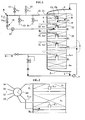
- the column comprises an enclosure 1, for example substantially cylindrical, which is filled with an adsorbent distributed in several beds A 1 to A n , at least one plate Pi distributing fluids being disposed between two beds of adsorbent.
- a plate Pi comprises one or more panels or DMEs having the function of distributing, extracting and / or mixing one or more fluids, each panel comprising a chamber Ci of distribution-extraction-mixture which is connected with the outside via a distribution spider fluids.
- the plate Pi includes in particular an upper grid 6 of maintenance of the adsorbent bed, a chamber Ci for distribution, extraction and / or mixing by panel, a lower grid 7, means such as a baffle 8 (cabinet in English) to separate the lower grid 7 from the grid upper 6.
- the cabinet 8 is provided with a central opening 9 allowing the circulation of fluids.
- Room Ci has for example in its part one or more Oi ports. These holes Oi let the fluid pass secondary. The latter is either introduced into the next bed after being mixed with the main fluid having passed through the main bed, or withdrawn by the appropriate transfer line.
- the main fluid circulates along the longitudinal axis or main axis of the column. It is extracted through a pipe 2, recycled via a pump 3 and a conduit 4 at the head of the column.
- Column can be arranged along a substantially vertical or even substantially horizontal axis.
- the main fluid flows inside the column in a flow of piston or plug flow type, the composition and the flow front being substantially uniform in all points of the column section.
- a fluid distribution device (not shown in the figure) in connection with the conduit 4 can optionally be fitted to the head of the column.
- a distribution, extraction and / or mixing chamber Ci is connected with the outside of the column by means of a circuit comprising a Ti conduit connected to several secondary fluid transfer lines. These lines include for example, a charge injection line 10, a line 11 for desorbent injection, line 12 for drawing off an extract and a line 13 for drawing off a raffinate.
- Each transfer line is equipped of valves Vfi, Vei, Vsi and Vri where the index i corresponds to the plateau Pi and where f denotes the charge, e the extract, s the desorbent and r the raffinate.
- All these valves is connected to sequential permutation means adapted to periodically advance each secondary fluid injection point or withdrawal of the secondary fluid from a bed in the direction of circulation of the main fluid, i.e. from top to bottom, so as to obtain a simulated moving counter current.
- sequential permutation means adapted to periodically advance each secondary fluid injection point or withdrawal of the secondary fluid from a bed in the direction of circulation of the main fluid, i.e. from top to bottom, so as to obtain a simulated moving counter current.
- a branch line Li, j is provided with at least one of the devices mentioned below taken alone or in combination combination, namely a non-return valve 14, a flow meter 15, a valve See, j for control, whether or not slaved to the flow meter. Possibly a pump arranged on the bypass line can possibly supplement a insufficient pressure drop.
- the valve fitted to the bypass circuit has the reference Voi, j where the index o corresponds to the derivation function and the indices i, j to the plates between which the diverted fluid circulates.
- upstream and downstream are defined in relation to the meaning flow of the main fluid in the column.
- a first end of the line L 1.2 carrying out the diversion of the fluid between the plate P 1 and the plate P 2 is connected by a connection point R to the line T 1 for introducing and / or extracting fluids which communicates with the chamber C 1 and the second end of the line L 1,2 is connected by appropriate means, some of the exemplary embodiments of which are detailed below. afterwards, to a region referenced R2 of the following plateau P 2 .
- Such an arrangement makes it possible to take a fraction of the main fluid from the chamber C1 from the bed A1 of the plate P 1 , to extract it via the conduit T 1 and to reinject it into the plate P2 via the bypass line L 1, 2 at the level of the region referenced R 2 .
- the fraction removed has the function of sweeping the bypass line and the distribution spider of the bed tray located A 1 immediately downstream.
- Figure 2 shows schematically another alternative embodiment differing from the Figure 1 by the circuit for introducing and extracting secondary fluids.
- the circuit includes a rotary valve 20 which has the function of connecting the different rooms Ci distribution, extraction and racking with fluid sources or conduits located outside the column and also to perform the function of deflection of the fluid.
- the fluid sampled from the chamber C 1 , from the plate P1 circulates in the line T 1 then using appropriate means located in the valve and described below, is sent in the bypass line L 1,2 at the level of the region R 2 disposed in the plate P2 relative to the bed of adsorbent A 2 .
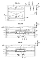
- the reinjection means can be formed by a line, arranged simply below the upper grid 6 of a tray, in an area 30 for collecting the main fluid (FIG. 3A, 3B) above the cabinet 8 or in a zone 31 for mixing the main fluid and the secondary fluids (fig 3C) contiguous to the distribution chamber 32 thus allowing the passage of the fraction of the main fluid taken from the chamber Ci of the plate Pi, in the region 30, 31 of the plate Pi + 1 (FIGS. 3A, 3B, 3C).
- the mixing chamber 31 according to FIG.
- 3B comprises at least three orifices: the diverted fluid injected in the volume between the upper grille 6 and the cabinet 8 enters the mixing chamber through port 34a. Minor part of the fluid flows in the distribution chamber 32 through the orifice 34b and most of the fluid flows to the lower grid through the lower orifice 34c. A jet breeze 35 under the orifice 34c disperses the collected fluid.
- the reinjection region 33 can also, according to a variant, be located under the cabinet 8 above the lower grid 7.
- FIG. 4 gives an example of connection of two successive plates showing the reinjection point of the line Lij in a region Ri + 1 of the collection space for one of the 4 pi + 1 panels on the distributor tray.
- the orientation of the panels pi and pi + 1 is perpendicular from one floor to the next, while the reinjection lines can form an angle of 120 ° from one floor to the next.
- FIG. 5 is a top view of a distribution system disposed at the periphery of a separation column 60.
- the column comprises several plates Pi distributed in a manner substantially similar to that described in the previous figures.
- Each plate Pi is formed of several panels each comprising a single chamber Ci of distribution-extraction-blending.
- a Pi plate can be cut into several sectors, for example 4 sectors in this exemplary embodiment.
- Each chamber Ci is connected to the distribution and extraction system of fluids via transfer lines 61 arranged for example as given below.
- the distribution system includes a transfer line 61 subdividing into two conduits 62, 63.
- Conduits 62 and 63 are subdivided themselves in two sub-conduits 62a, 62b and 63a, 63b allowing to distribute and / or extract fluids to or from the four sectors of the tray.
- the end of a sub-duct 62a, 62b, 63a, 63b distinct from the point of junction J comprises in a given zone, one or more conduits 64 of which the number is equal to the number of panels forming a sector. Fluids thus reach the panels forming a plate substantially at the same moment.
Landscapes
- Chemical & Material Sciences (AREA)
- Life Sciences & Earth Sciences (AREA)
- Sustainable Development (AREA)
- Analytical Chemistry (AREA)
- Chemical Kinetics & Catalysis (AREA)
- Treatment Of Liquids With Adsorbents In General (AREA)
Abstract
Description
- au moins une enceinte ou colonne, comportant un ou plusieurs lits d'adsorbants (Ai), deux lits d'adsorbants étant séparés par au moins un plateau (Pi) de distribution et d'extraction de fluides, le plateau comportant un ou plusieurs panneaux permettant de distribuer, mélanger et/ou extraire des fluides,
- au moins un conduit d'introduction d'un fluide principal et au moins un conduit d'extraction du fluide principal,
- plusieurs conduits permettant d'extraire ou d'injecter des fluides secondaires,
- un circuit de dérivation mettant en communication un plateau de distribution avec au moins une ligne (Li,j ) de dérivation,
- le panneau comporte une seule chambre (Ci) de distribution, mélange et /ou d'extraction.
- le dispositif comporte des moyens (14, Voi,j, 20) de mise en communication d'au moins une chambre (Ci) avec au moins une ligne (Li,j) de dérivation,
- une des extrémités de la ligne de dérivation est en liaison avec ladite chambre Ci d'un panneau du plateau Pi, et l'autre extrêmité communique avec une région (Ri + 1) d'un panneau du plateau de distribution Pi + 1, ladite région étant distincte de la chambre de distribution Ci + 1.
- un stator pourvu de plusieurs moyens de circulation (E, F, R, S, D) du ou des fluides du groupe G1, des moyens de passage d'au moins deux fluides F1, F2 appartenant au groupe G3,
- un rotor équipé de moyens de passage des fluides du groupe G3 et aussi des moyens permettant la mise en communication soit des fluides de groupe G1 avec le groupe G3, ou bien du groupe G3 avec le groupe G3,
- le nombre des moyens de passage pour le fluide F1 est sensiblement identique au nombre des moyens de passage pour le fluide F2, ladite vanne comporte des moyens de mise en communication d'au moins deux fluides du groupe G3 et en ce que la section S1 de passage des lumières pour le fluide F1 est différente de la section de passage S2 des lumières destinées au fluide F2.
- on fait circuler un fluide principal à travers plusieurs lits d'adsorbants, disposés entre des plateaux de distribution,
- on injecte et on extrait des fluides secondaires (charge, désorbant, ..) selon une séquence appropriée pour réaliser la séparation des constituants à séparer de la charge,
- on injecte un fluide dévié d'un plateau Pi vers le suivant (Pi + 1).
- la figure 1 représente une disposition des lignes de dérivation par rapport à une colonne de séparation,
- la figure 2 représente un mode de réalisation utilisant des vannes de type " rotatives ",
- les figures 3A 3B 3C donnent des exemples de dispositifs d'injection du fluide dévié disposé dans le plateau distributeur, par exemple dans une zone de collecte (fig 3B) ou dans une zone de mélange (fig 3C)
- la figure 4 représente un exemple de liaison de deux plateaux successifs avec une orientation des panneaux perpendiculaire d'un étage au suivant,
- la figure 5 montre une vue de dessus d'un système de distribution disposé autour d'une colonne de séparation,
- soit les lignes de transfert 10, 11, 12, 13 des fluides secondaires avec les lignes de transfert Ti,
- soit d'une zone Ri + 1 d'un plateau Pi + 1 avec une chambre Ci d'injection d'extraction, mélange d'un plateau Pi pour réaliser la fonction de déviation du fluide,
- soit éventuellement les lignes de transfert 10, 11, 12, 13 avec les lignes Li,j de dérivation et les lignes de transfert Ti pour réaliser la fonction de déviation ou de dérivation du fluide, et simultanément l'injection ou l'extraction.
Claims (10)
- Dispositif permettant de séparer au moins un composé à partir d'un mélange ou d'un corps par adsorption, en lit mobile simulé comportant :caractérisé en ce que :au moins une enceinte ou colonne, comportant un ou plusieurs lits d'adsorbants (Ai), deux lits d'adsorbants étant séparés par au moins un plateau (Pi) de distribution et d'extraction de fluides, le plateau comportant un ou plusieurs panneaux de distribution permettant de distribuer, mélanger et/ou extraire des fluides,au moins un conduit (4) d'introduction d'un fluide principal et un conduit (2) d'extraction du fluide principal,plusieurs conduits (10, 11, 12, 13, Ti) permettant d'extraire ou d'injecter des fluides secondaires,un circuit de dérivation mettant en communication un plateau de distribution avec au moins une ligne (Li,j ) de dérivation,le panneau comporte une seule chambre (Ci) de distribution, mélange et /ou d'extraction,le dispositif comporte des moyens (14, Voi,j, 20) de mise en communication d'au moins une chambre (Ci) avec au moins une ligne (Li,j) de dérivation,une des extrémités de la ligne de dérivation est en liaison avec ladite chambre Ci d'un panneau du plateau Pi, et l'autre extrêmité communique avec une région (Ri + 1) d'un panneau du plateau de distribution Pi + 1, ladite région étant distincte de la chambre de distribution Ci + 1.
- Dispositif selon la revendication 1 caractérisé en ce que lesdits moyens de mise en communication comportent au moins une vanne Voi,j disposée sur au moins une ligne (Li,j) de dérivation et en ce que l'extrémité de la ligne de dérivation qui n'est pas liée à la région du plateau est reliée à une ligne (Ti) d'introduction et/ou d'extraction.
- Dispositif selon la revendication 1 caractérisé en ce que lesdits moyens de mise en communication comportent au moins une vanne rotative (20), ladite vanne rotative étant reliée à au moins une ligne (Ti) d'introduction et/ou d'extraction et au moins à une ligne (Li,j) de dérivation, ladite vanne comportant des moyens permettant au moins de faire communiquer une ligne d'introduction et/ou d'extraction à au moins une ligne de dérivation.
- Dispositif selon l'une des revendications 1 à 3 caractérisé en ce que le circuit de distribution des fluides est disposé autour de ladite enceinte, et en ce qu'il comporte une ligne principale (61) qui se divise en plusieurs lignes secondaires (62, 63, 62a, 62b,) afin que le ou les fluides atteignent les panneaux formant un plateau sensiblement au même instant.
- Dispositif selon l'une des revendications 1 à 4 caractérisé en ce que les plateaux ont une découpe de type parallèle, en ce que le dispositif de distribution de fluide comporte un conduit principal, connecté à des conduits secondaires relatifs à chacun des panneaux du plateau et en ce que la ligne de dérivation est en liaison avec une région d'un panneau.
- Dispositif selon l'une des revendications 1 à 5 caractérisé en ce qu'un plateau est délimité par une grille inférieure (7) et une grille supérieure (6) et en ce que l'extrémité de la ligne de dérivation en liaison avec la chambre de distribution d'un plateau Pi est reliée à un moyen de distribution disposé en-dessous de ladite grille supérieure dans un espace de collecte (30) d'un plateau aval (Pi + 1).
- Dispositif selon l'une des revendications 1 à 5 caractérisé en ce qu'un plateau est délimité par une grille inférieure (7) et une grille supérieure (6) et en ce que l'extrémité de la ligne de dérivation en liaison avec la chambre de distribution d'un plateau Pi est reliée à un moyen de distribution disposé en-dessous de ladite grille supérieure dans une chambre de mélange (31) contiguë à la chambre de distribution (32) du plateau Pi + 1.
- Procédé d'injection d'un fluide dévié dans un procédé de séparation de constituants d'ue charge par lit mobile simulé comportant au moins les étapes suivantes :caractérisé en ce que l'on fait circuler au moins une partie du fluide principal à l'extérieur de l'enceinte permettant de réaliser la séparation par l'intermédiaire d'une ligne de dérivation, une des extrémités de la ligne étant en liaison avec une chambre Ci de distribution du plateau Pi et l'autre extrêmité étant en liaison avec une région d'un plateau distributeur suivant Pi + 1, distincte d'une chambre Ci + 1 dudit plateau Pi + 1.on fait circuler un fluide principal à travers plusieurs lits d'adsorbants contenus entre des plateaux,on injecte et on extrait des fluides secondaires (charge, désorbant, ..) selon une séquence appropriée pour réaliser la séparation des constituants de la charge,on injecte un fluide dévié d'un plateau vers le suivant,
- Procédé selon la revendication 8 caractérisé en ce que l'on prélève à partir d'une chambre (Ci) une fraction du fluide principal et on injecte ladite fraction dans une chambre de mélange (31) contiguë à une chambre de distribution Ci + 1, (32) du plateau suivant.
- Application du dispositif selon l'une des revendications 1 à 7 et du procédé selon l'une des revendications 8 à 9 à la séparation des normales paraffines de C10 à C13 à partir de charges de type kérosène adouci.
Applications Claiming Priority (2)
| Application Number | Priority Date | Filing Date | Title |
|---|---|---|---|
| FR0116444 | 2001-12-19 | ||
| FR0116444A FR2833499B1 (fr) | 2001-12-19 | 2001-12-19 | Dispositif d'injection d'un fluide devie dans un procede de separation en lit mobile simule |
Publications (2)
| Publication Number | Publication Date |
|---|---|
| EP1325772A1 true EP1325772A1 (fr) | 2003-07-09 |
| EP1325772B1 EP1325772B1 (fr) | 2009-08-19 |
Family
ID=8870681
Family Applications (1)
| Application Number | Title | Priority Date | Filing Date |
|---|---|---|---|
| EP02292864A Expired - Lifetime EP1325772B1 (fr) | 2001-12-19 | 2002-11-19 | Dispositif d'injection d'un fluide dévié dans un procédé de séparation en lit mobile simulé |
Country Status (5)
| Country | Link |
|---|---|
| US (1) | US6797175B2 (fr) |
| EP (1) | EP1325772B1 (fr) |
| DE (1) | DE60233381D1 (fr) |
| ES (1) | ES2329767T3 (fr) |
| FR (1) | FR2833499B1 (fr) |
Cited By (7)
| Publication number | Priority date | Publication date | Assignee | Title |
|---|---|---|---|---|
| FR2904776A1 (fr) * | 2006-08-08 | 2008-02-15 | Inst Francais Du Petrole | Procede et dispositif de separation en lit mobile simule a nombre de vannes reduit |
| FR2907021A1 (fr) * | 2006-10-16 | 2008-04-18 | Inst Francais Du Petrole | Procede et dispositif de separation en lit mobile simule a nombre de vannes de grand diametre reduit |
| FR2913345A1 (fr) * | 2007-03-09 | 2008-09-12 | Inst Francais Du Petrole | Procede et dispositif de separation en lit mobile simule a nombre de vannes et volume de lignes reduits |
| FR2913346A1 (fr) * | 2007-03-09 | 2008-09-12 | Inst Francais Du Petrole | Procede et dispositif de separation en lit mobile simule a nombre de vannes de grand diametre et volume de lignes reduits |
| EP1812132A4 (fr) * | 2004-11-19 | 2009-03-18 | Uop Llc | Appareil de distribution de fluide |
| EP2138215A1 (fr) * | 2008-06-27 | 2009-12-30 | Ifp | Système de distribution et de collecte dans une colonne multiétagée permettant d'égaliser les temps de séjour sur chaque étage |
| CN101940850A (zh) * | 2010-09-29 | 2011-01-12 | 西安航天华威化工生物工程有限公司 | 顺序式模拟移动床 |
Families Citing this family (20)
| Publication number | Priority date | Publication date | Assignee | Title |
|---|---|---|---|---|
| FR2794663B1 (fr) * | 1999-06-09 | 2001-07-13 | Inst Francais Du Petrole | Systeme d'injection d'un fluide devie dans un procede de separation en lit mobile simule |
| US7722832B2 (en) | 2003-03-25 | 2010-05-25 | Crystaphase International, Inc. | Separation method and assembly for process streams in component separation units |
| US7544293B2 (en) | 2005-09-26 | 2009-06-09 | Semba Inc. | Valve and process for interrupted continuous flow chromatography |
| EP1775001A1 (fr) | 2005-10-13 | 2007-04-18 | Xendo Holding B.V. | Dispositif pour séparations chromatographiques |
| US7790040B2 (en) | 2006-08-30 | 2010-09-07 | Semba Biosciences, Inc. | Continuous isocratic affinity chromatography |
| US8807164B2 (en) | 2006-08-30 | 2014-08-19 | Semba Biosciences, Inc. | Valve module and methods for simulated moving bed chromatography |
| FR2935101B1 (fr) * | 2008-08-19 | 2011-04-08 | Inst Francais Du Petrole | Procede et dispostif de separation en lit mobile simule a debit de fluide de derivation non regule automatiquement |
| FR2935100B1 (fr) | 2008-08-19 | 2011-03-18 | Inst Francais Du Petrole | Procede et dispositif de separation en lit mobile simule a debit de fluide de derivation module |
| US8196603B2 (en) | 2008-08-20 | 2012-06-12 | Semba Biosciences, Inc. | Valve block assembly |
| US8201988B2 (en) * | 2009-03-18 | 2012-06-19 | Uop Llc | Adsorber grid distributor box design |
| FR2944215B1 (fr) * | 2009-04-10 | 2011-04-01 | Inst Francais Du Petrole | Procede et dispositif de separation en lit mobile simule comportant des lignes de derivation d'un lit sur deux et a debit de fluide de derivation module |
| FR2956037B1 (fr) * | 2010-02-11 | 2012-02-17 | Inst Francais Du Petrole | Procede et dispositif de separation en lit mobile simule comportant des lignes de derivation d'un lit sur deux avec debits de balayage controles lors des injections et des soutirages |
| US9162205B2 (en) | 2012-12-31 | 2015-10-20 | Uop Llc | Apparatuses for distributing fluids in fluidized bed reactors |
| US10744426B2 (en) | 2015-12-31 | 2020-08-18 | Crystaphase Products, Inc. | Structured elements and methods of use |
| US10054140B2 (en) | 2016-02-12 | 2018-08-21 | Crystaphase Products, Inc. | Use of treating elements to facilitate flow in vessels |
| FR3082754B1 (fr) | 2018-06-20 | 2022-12-30 | Ifp Energies Now | Procede et dispositif de separation en lit mobile simule a debit de fluide de derivation |
| FR3082755B1 (fr) | 2018-06-20 | 2022-12-30 | Ifp Energies Now | Procede et dispositif de separation en lit mobile simule a nombre de lits reduit avec debit de fluide de derivation |
| EP4076719A1 (fr) | 2019-12-20 | 2022-10-26 | Crystaphase Products Inc. | Resaturation de gaz dans un courant d'alimentation en liquide |
| US11752477B2 (en) | 2020-09-09 | 2023-09-12 | Crystaphase Products, Inc. | Process vessel entry zones |
| FR3127413B1 (fr) * | 2021-09-30 | 2023-10-20 | Ifp Energies Now | Dispositif et procédé de séparation en lit mobile simulé à brise jet étendu |
Citations (2)
| Publication number | Priority date | Publication date | Assignee | Title |
|---|---|---|---|---|
| FR2772634A1 (fr) * | 1997-12-22 | 1999-06-25 | Inst Francais Du Petrole | Procede et dispositif d'amelioration de la purete d'un produit en lit mobile simule |
| FR2794663A1 (fr) | 1999-06-09 | 2000-12-15 | Inst Francais Du Petrole | Systeme d'injection d'un fluide devie dans un procede de separation en lit mobile simule |
Family Cites Families (1)
| Publication number | Priority date | Publication date | Assignee | Title |
|---|---|---|---|---|
| FR2782657B1 (fr) * | 1998-09-02 | 2000-09-29 | Inst Francais Du Petrole | Systeme distributeur-collecteur de fluides et son procede |
-
2001
- 2001-12-19 FR FR0116444A patent/FR2833499B1/fr not_active Expired - Fee Related
-
2002
- 2002-11-19 EP EP02292864A patent/EP1325772B1/fr not_active Expired - Lifetime
- 2002-11-19 DE DE60233381T patent/DE60233381D1/de not_active Expired - Lifetime
- 2002-11-19 ES ES02292864T patent/ES2329767T3/es not_active Expired - Lifetime
- 2002-12-17 US US10/320,714 patent/US6797175B2/en not_active Expired - Lifetime
Patent Citations (2)
| Publication number | Priority date | Publication date | Assignee | Title |
|---|---|---|---|---|
| FR2772634A1 (fr) * | 1997-12-22 | 1999-06-25 | Inst Francais Du Petrole | Procede et dispositif d'amelioration de la purete d'un produit en lit mobile simule |
| FR2794663A1 (fr) | 1999-06-09 | 2000-12-15 | Inst Francais Du Petrole | Systeme d'injection d'un fluide devie dans un procede de separation en lit mobile simule |
Cited By (18)
| Publication number | Priority date | Publication date | Assignee | Title |
|---|---|---|---|---|
| EP1812132A4 (fr) * | 2004-11-19 | 2009-03-18 | Uop Llc | Appareil de distribution de fluide |
| CN101143274B (zh) * | 2006-08-08 | 2012-03-14 | Ifp公司 | 采用减少的阀数目的模拟移动床分离方法与设备 |
| US7582206B2 (en) | 2006-08-08 | 2009-09-01 | Institut Francais Du Petrole | Process and device for simulated moving bed separation with a reduced number of valves |
| FR2904776A1 (fr) * | 2006-08-08 | 2008-02-15 | Inst Francais Du Petrole | Procede et dispositif de separation en lit mobile simule a nombre de vannes reduit |
| FR2907021A1 (fr) * | 2006-10-16 | 2008-04-18 | Inst Francais Du Petrole | Procede et dispositif de separation en lit mobile simule a nombre de vannes de grand diametre reduit |
| EP1913988A1 (fr) * | 2006-10-16 | 2008-04-23 | Ifp | Procédé et dispositif de séparation en lit mobile simulé à nombre de vannes de grand diametre reduit |
| US7582207B2 (en) | 2006-10-16 | 2009-09-01 | Institut Francais Du Petrole | Process and device for simulated moving bed separation with a reduced number of large diameter valves |
| US7569141B2 (en) | 2007-03-09 | 2009-08-04 | Institut Francais Du Petrole | Process and device for simulated moving bed separation with a reduced number of large diameter valves and a reduced line volume |
| WO2008122705A3 (fr) * | 2007-03-09 | 2008-11-20 | Inst Francais Du Petrole | Procede et dispositif de separation en lit mobile simule a nombre de vannes de grand diametre et volume de lignes reduits |
| US7582208B2 (en) | 2007-03-09 | 2009-09-01 | Institut Francais Du Petrole | Process and device for simulated moving bed separation with a reduced number of valves and lines |
| WO2008125751A1 (fr) * | 2007-03-09 | 2008-10-23 | Ifp | Procede et dispositif de separation en lit mobile simule a nombre de vannes et volume de lignes reduits |
| FR2913346A1 (fr) * | 2007-03-09 | 2008-09-12 | Inst Francais Du Petrole | Procede et dispositif de separation en lit mobile simule a nombre de vannes de grand diametre et volume de lignes reduits |
| FR2913345A1 (fr) * | 2007-03-09 | 2008-09-12 | Inst Francais Du Petrole | Procede et dispositif de separation en lit mobile simule a nombre de vannes et volume de lignes reduits |
| EP2138215A1 (fr) * | 2008-06-27 | 2009-12-30 | Ifp | Système de distribution et de collecte dans une colonne multiétagée permettant d'égaliser les temps de séjour sur chaque étage |
| FR2933000A1 (fr) * | 2008-06-27 | 2010-01-01 | Inst Francais Du Petrole | Nouveau systeme de distribution et de collecte dans une colonne multi etagee permettant d'egaliser les temps de sejour sur chaque etage |
| US8318024B2 (en) | 2008-06-27 | 2012-11-27 | IFP Energies Nouvelles | System and method for distribution of fluid a multistage column |
| CN101940850A (zh) * | 2010-09-29 | 2011-01-12 | 西安航天华威化工生物工程有限公司 | 顺序式模拟移动床 |
| CN101940850B (zh) * | 2010-09-29 | 2012-08-29 | 西安航天华威化工生物工程有限公司 | 顺序式模拟移动床 |
Also Published As
| Publication number | Publication date |
|---|---|
| DE60233381D1 (de) | 2009-10-01 |
| FR2833499B1 (fr) | 2004-08-20 |
| ES2329767T3 (es) | 2009-12-01 |
| US6797175B2 (en) | 2004-09-28 |
| EP1325772B1 (fr) | 2009-08-19 |
| FR2833499A1 (fr) | 2003-06-20 |
| US20030127394A1 (en) | 2003-07-10 |
Similar Documents
| Publication | Publication Date | Title |
|---|---|---|
| EP1325772B1 (fr) | Dispositif d'injection d'un fluide dévié dans un procédé de séparation en lit mobile simulé | |
| EP1102615B1 (fr) | Systeme d'injection d'un fluide devie dans un procede de separation en lit mobile simule | |
| EP1913988B1 (fr) | Procédé et dispositif de séparation en lit mobile simulé à nombre de vannes de grand diametre reduit | |
| EP1113866B1 (fr) | Systeme distributeur-collecteur de fluides et son procede | |
| EP0923970B1 (fr) | Procédé et dispositif d'amélioration de la pureté d'un produit en lit mobile simulé | |
| FR2794836A1 (fr) | Vanne rotative amelioree | |
| WO2008125751A1 (fr) | Procede et dispositif de separation en lit mobile simule a nombre de vannes et volume de lignes reduits | |
| EP0821988B1 (fr) | Dispositif et procédé de rinçage en lit mobile simulé comportant au moins deux lignes de distribution de fluides | |
| EP1600675A1 (fr) | Procédé et dispositif perfectionné de séparation en lit mobile simulé | |
| EP1113867A1 (fr) | Distributeur-melangeur-extracteur de fluides et procede associe | |
| FR2904776A1 (fr) | Procede et dispositif de separation en lit mobile simule a nombre de vannes reduit | |
| EP0769316A1 (fr) | Distributeur permettant l'injection et/ou le soutirage indépendant de fluides | |
| EP2138215B1 (fr) | Système de distribution et de collecte dans une colonne multiétagée permettant d'égaliser les temps de séjour sur chaque étage | |
| FR2956037A1 (fr) | Procede et dispositif de separation en lit mobile simule comportant des lignes de derivation d'un lit sur deux avec debits de balayage controles lors des injections et des soutirages | |
| EP1646437B1 (fr) | Procede et dispositif de separation des constituants d'une charge liquide par chromatographie liquide-liquide centrifuge | |
| FR2935101A1 (fr) | Procede et dispostif de separation en lit mobile simule a debit de fluide de derivation non regule automatiquement | |
| CA2272638C (fr) | Dispositif de regulation de debit d'au moins un fluide d'unites de separation par lit mobile simule | |
| FR2935100A1 (fr) | Procede et dispositif de separation en lit mobile simule a debit de fluide de derivation module | |
| EP0846483B1 (fr) | Dispositif de rinçage dans une unité d'adsorption en lit mobile simulé comprenant deux lignes de distribution de fluides et son utilisation | |
| FR2913346A1 (fr) | Procede et dispositif de separation en lit mobile simule a nombre de vannes de grand diametre et volume de lignes reduits | |
| FR2781860A1 (fr) | Systeme de mise en communication alternee d'au moins quatre fluides et son application dans un procede de separation en lit mobile simule | |
| FR2777798A1 (fr) | Procede et dispositif d'amelioration de la purete d'un produit en lit mobile simule comprenant une recirculation forcee de fluide | |
| FR2856313A1 (fr) | Methode de gestion des vannes d'un systeme de separation a lit mobile simule | |
| FR2794666A1 (fr) | Element de mat ayant une fonction de distribution | |
| EP3583988B1 (fr) | Procédé et dispositif de séparation en lit mobile simulé à nombre de lits réduit avec débit de fluide de dérivation |
Legal Events
| Date | Code | Title | Description |
|---|---|---|---|
| PUAI | Public reference made under article 153(3) epc to a published international application that has entered the european phase |
Free format text: ORIGINAL CODE: 0009012 |
|
| AK | Designated contracting states |
Designated state(s): AT BE BG CH CY CZ DE DK EE ES FI FR GB GR IE IT LI LU MC NL PT SE SK TR |
|
| AX | Request for extension of the european patent |
Extension state: AL LT LV MK RO SI |
|
| 17P | Request for examination filed |
Effective date: 20040109 |
|
| AKX | Designation fees paid |
Designated state(s): DE ES IT NL |
|
| 17Q | First examination report despatched |
Effective date: 20071009 |
|
| RTI1 | Title (correction) |
Free format text: SYSTEM FOR INJECTING A BY-PASS FLUID IN A SIMULATED MOVING BED SEPARATION METHOD |
|
| GRAP | Despatch of communication of intention to grant a patent |
Free format text: ORIGINAL CODE: EPIDOSNIGR1 |
|
| GRAS | Grant fee paid |
Free format text: ORIGINAL CODE: EPIDOSNIGR3 |
|
| GRAA | (expected) grant |
Free format text: ORIGINAL CODE: 0009210 |
|
| AK | Designated contracting states |
Kind code of ref document: B1 Designated state(s): DE ES IT NL |
|
| REF | Corresponds to: |
Ref document number: 60233381 Country of ref document: DE Date of ref document: 20091001 Kind code of ref document: P |
|
| REG | Reference to a national code |
Ref country code: ES Ref legal event code: FG2A Ref document number: 2329767 Country of ref document: ES Kind code of ref document: T3 |
|
| PLBE | No opposition filed within time limit |
Free format text: ORIGINAL CODE: 0009261 |
|
| STAA | Information on the status of an ep patent application or granted ep patent |
Free format text: STATUS: NO OPPOSITION FILED WITHIN TIME LIMIT |
|
| 26N | No opposition filed |
Effective date: 20100520 |
|
| REG | Reference to a national code |
Ref country code: DE Ref legal event code: R081 Ref document number: 60233381 Country of ref document: DE Owner name: IFP ENERGIES NOUVELLES, FR Free format text: FORMER OWNER: INSTITUT FRANCAIS DU PETROLE, RUEIL-MALMAISON, HAUTS-DE-SEINE, FR Effective date: 20110331 |
|
| PGFP | Annual fee paid to national office [announced via postgrant information from national office to epo] |
Ref country code: NL Payment date: 20181123 Year of fee payment: 17 |
|
| PGFP | Annual fee paid to national office [announced via postgrant information from national office to epo] |
Ref country code: DE Payment date: 20181203 Year of fee payment: 17 |
|
| PGFP | Annual fee paid to national office [announced via postgrant information from national office to epo] |
Ref country code: ES Payment date: 20181214 Year of fee payment: 17 Ref country code: IT Payment date: 20181130 Year of fee payment: 17 |
|
| REG | Reference to a national code |
Ref country code: DE Ref legal event code: R119 Ref document number: 60233381 Country of ref document: DE |
|
| REG | Reference to a national code |
Ref country code: NL Ref legal event code: MM Effective date: 20191201 |
|
| PG25 | Lapsed in a contracting state [announced via postgrant information from national office to epo] |
Ref country code: NL Free format text: LAPSE BECAUSE OF NON-PAYMENT OF DUE FEES Effective date: 20191201 |
|
| PG25 | Lapsed in a contracting state [announced via postgrant information from national office to epo] |
Ref country code: DE Free format text: LAPSE BECAUSE OF NON-PAYMENT OF DUE FEES Effective date: 20200603 Ref country code: IT Free format text: LAPSE BECAUSE OF NON-PAYMENT OF DUE FEES Effective date: 20191119 |
|
| REG | Reference to a national code |
Ref country code: ES Ref legal event code: FD2A Effective date: 20210527 |
|
| PG25 | Lapsed in a contracting state [announced via postgrant information from national office to epo] |
Ref country code: ES Free format text: LAPSE BECAUSE OF NON-PAYMENT OF DUE FEES Effective date: 20191120 |