EP1324890B1 - Steckverbindungseinrichtung - Google Patents
Steckverbindungseinrichtung Download PDFInfo
- Publication number
- EP1324890B1 EP1324890B1 EP02781264A EP02781264A EP1324890B1 EP 1324890 B1 EP1324890 B1 EP 1324890B1 EP 02781264 A EP02781264 A EP 02781264A EP 02781264 A EP02781264 A EP 02781264A EP 1324890 B1 EP1324890 B1 EP 1324890B1
- Authority
- EP
- European Patent Office
- Prior art keywords
- plug
- socket
- contact
- plug housing
- spring
- Prior art date
- Legal status (The legal status is an assumption and is not a legal conclusion. Google has not performed a legal analysis and makes no representation as to the accuracy of the status listed.)
- Expired - Lifetime
Links
Images




Classifications
-
- B—PERFORMING OPERATIONS; TRANSPORTING
- B60—VEHICLES IN GENERAL
- B60D—VEHICLE CONNECTIONS
- B60D1/00—Traction couplings; Hitches; Draw-gear; Towing devices
- B60D1/58—Auxiliary devices
- B60D1/62—Auxiliary devices involving supply lines, electric circuits or the like
- B60D1/64—Couplings or joints therefor
-
- B—PERFORMING OPERATIONS; TRANSPORTING
- B60—VEHICLES IN GENERAL
- B60D—VEHICLE CONNECTIONS
- B60D1/00—Traction couplings; Hitches; Draw-gear; Towing devices
- B60D1/58—Auxiliary devices
- B60D1/62—Auxiliary devices involving supply lines, electric circuits or the like
-
- H—ELECTRICITY
- H01—ELECTRIC ELEMENTS
- H01R—ELECTRICALLY-CONDUCTIVE CONNECTIONS; STRUCTURAL ASSOCIATIONS OF A PLURALITY OF MUTUALLY-INSULATED ELECTRICAL CONNECTING ELEMENTS; COUPLING DEVICES; CURRENT COLLECTORS
- H01R13/00—Details of coupling devices of the kinds covered by groups H01R12/70 or H01R24/00 - H01R33/00
- H01R13/62—Means for facilitating engagement or disengagement of coupling parts or for holding them in engagement
- H01R13/629—Additional means for facilitating engagement or disengagement of coupling parts, e.g. aligning or guiding means, levers, gas pressure electrical locking indicators, manufacturing tolerances
- H01R13/631—Additional means for facilitating engagement or disengagement of coupling parts, e.g. aligning or guiding means, levers, gas pressure electrical locking indicators, manufacturing tolerances for engagement only
- H01R13/6315—Additional means for facilitating engagement or disengagement of coupling parts, e.g. aligning or guiding means, levers, gas pressure electrical locking indicators, manufacturing tolerances for engagement only allowing relative movement between coupling parts, e.g. floating connection
-
- H—ELECTRICITY
- H01—ELECTRIC ELEMENTS
- H01R—ELECTRICALLY-CONDUCTIVE CONNECTIONS; STRUCTURAL ASSOCIATIONS OF A PLURALITY OF MUTUALLY-INSULATED ELECTRICAL CONNECTING ELEMENTS; COUPLING DEVICES; CURRENT COLLECTORS
- H01R13/00—Details of coupling devices of the kinds covered by groups H01R12/70 or H01R24/00 - H01R33/00
- H01R13/62—Means for facilitating engagement or disengagement of coupling parts or for holding them in engagement
- H01R13/629—Additional means for facilitating engagement or disengagement of coupling parts, e.g. aligning or guiding means, levers, gas pressure electrical locking indicators, manufacturing tolerances
- H01R13/633—Additional means for facilitating engagement or disengagement of coupling parts, e.g. aligning or guiding means, levers, gas pressure electrical locking indicators, manufacturing tolerances for disengagement only
- H01R13/635—Additional means for facilitating engagement or disengagement of coupling parts, e.g. aligning or guiding means, levers, gas pressure electrical locking indicators, manufacturing tolerances for disengagement only by mechanical pressure, e.g. spring force
Definitions
- the invention relates to a connector for the automatic e.g. Multi-pole electrical connection of a vehicle trailer, in particular of a semi-trailer, to a towing vehicle, in particular to one Semitrailer, with a socket and a plug, which on the vehicle trailer (e.g. the plug) or the towing vehicle (e.g. the socket) can be arranged, can be aligned with each other when coupling the vehicle trailer to the towing vehicle and by means of e.g.
- the object of the present invention is a connector device to propose the type mentioned, in which one without manual operation great and automatic finding friendliness of the two plug elements to each other given is.
- the solution according to the invention ensures that the automatic Merging plug and socket even with larger tolerances or Inaccuracy of sensing can be easily and safely manufactured.
- the retaining spring for the plug in a special embodiment of the invention as surrounding the connector housing Spring spiral formed, which is preferably forward in her Tapered diameter.
- the task set is still in further development of the inventive concept better solved if the connector housing has an insertion funnel for the socket has, because with the help of the can even with tolerance-related deviations the orientation can be securely inserted into the connector.
- the lateral deflection of the plug can be done in a simple manner, for example ensure that the connector housing on the rear e.g. via a ball bearing is supported on a holding plate.
- a further feature of the invention which is e.g. also as Mounting flange serving mounting flange guided holding plate for the The connector housing is supported on a return spring. That way, too lateral pivoting of the connector housing against the action of the return spring as well as the retaining spring for the connector.
- the contact pins load-bearing contact housing receiving plug housing e.g. Behind the insertion funnel closed in the rest position by a cover plate is which preferably has through openings for the contact pins and against the action of a return spring from the front rest position and the Release of the contact pins movable into a rear connection position, is particularly displaceable.
- an automatic opening and closing the connector housing by inserting and withdrawing the can itself does.
- the arrangement is preferably made so that in the rest position of the cover plate, the contact pins the passage openings just close. Because of this, the contact pins can be used as a guide for serve the cover plate in their back and forth movement.
- the cover plate in the rest position of its return spring on her outer edge, possibly under the intermediate layer of a sealing ring, to an inner shoulder of the connector housing is pressed.
- the sealing ring can be at the front end of a spacer sleeve in the Be plug or the connector housing held.
- the return spring for the cover plate can also give the contact attachment as a spring spiral and preferably with yours rear end to be received in an annular groove.
- the connector housing can be equipped with a a valve core receiving plug, which is in the installed state points down.
- a baffle is provided in the valve core through which Condensation can drip, but the ingress of water (splash water, Steam jets) is prevented from the outside.
- the drive lockable in the connection position and / or the rest position of the box is the drive lockable in the connection position and / or the rest position of the box.
- the contact insert can be used to simplify assembly and disassembly the piston of the as e.g. trained pneumatic piston-cylinder arrangement Drive can be releasably attached, for example with a screw.
- the contact insert in a further embodiment of the invention the can on a e.g. also serves as a mounting plate guided against rotation.
- the connector device according to the invention can optionally with a Emergency release, which means mechanical disconnection of the socket in the event of a power failure and plug allows an anti-twist protection of the socket, a coding protection of the Socket, sensors for position detection of the socket, a fuse for the connector housing against lifting off the holding plate and / or locking means of the Have contact insert in retracted and extended position to ensure functional reliability still increase.
- a Emergency release means mechanical disconnection of the socket in the event of a power failure and plug allows an anti-twist protection of the socket, a coding protection of the Socket, sensors for position detection of the socket, a fuse for the connector housing against lifting off the holding plate and / or locking means of the Have contact insert in retracted and extended position to ensure functional reliability still increase.
- the connector device shown in the figures which, for example, at a combination semi-trailer / semi-trailer can be used and then located in the area of the fifth wheel coupling, consists of e.g. on the plug to be attached to the vehicle trailer and a e.g. on the towing vehicle socket to be attached D.
- a sensor arrangement that detects the position of the vehicle trailer is determined relative to the towing vehicle.
- the two Plug elements D, S put together.
- the drive 10 is designed such that he the socket D from a retracted rest position when the connector is not used in an advanced connection position when the Plug connection is to be made, in which the socket D interacts with the connector S. When you disconnect the connector, the Direction of movement of the can D reversed.
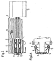
- the can D has one two flaps formed cover 5.
- the flaps of the cover 5 are on Pivot axes 9 of an annular housing section 16 of a base plate 2 against the action of return springs designed as leg springs 4 pivoted in such a way that when the base plate 2 guided contact insert 1 in the connecting position, the two flaps of the Swing cover 5 outwards and when pulling back the contact insert 1 in the retracted rest position by means of the return springs 4 again be brought into their closed position.
- the front is for secure sealing End of the contact insert 1 or the housing section 16 with a Provide sealing washer 3, to which the flaps of the cover 5 in the closed position can put on.
- a twist-proof guidance of the contact insert 1 takes place on the housing section 16 with the aid of an outer longitudinal groove 14 in Jacket of the contact insert 1 and an associated inner longitudinal rib 15 of the housing section 16.
- the contact insert 1 is by means of an Allen screw 6 at the front end of the piston 17 of the piston-cylinder arrangement 10 releasably attached.
- a cable 7 for the supply of the contact insert 1 is cast into the base plate 2 and relieved of tension by means of a clamp 13.
- the drive 10 is both in the advanced connection position and locked in the retracted rest position of the can D to the can D in secure both positions against changes in position.
- the retaining spring 213 for the connector S is as the connector housing 29 surrounding spring spiral formed, which, as a double spiral spring formed, with their rear free ends 33 on a mounting flange 210 is fixed, which can also serve as a mounting flange.
- the Retaining spring 213 tapers forward in diameter to give it the required To give back characteristics.
- the connector housing 29 has an insertion funnel at its front end 30 for the D can to compensate for alignment tolerances.
- the connector housing 29 is on a ball bearing 26 on a Retaining plate 27 supported to avoid sideways evasion to enable the retaining spring 213.
- the connector housing 29 takes a contact pin 21, 22 carrying contact attachment 28 on.
- the plug housing 29 is in the rest position shown in FIG. 4 closed by a cover plate 23 which, for example, passage openings for the contact pins 21, 22, which in the rest position, the passage openings just close.
- the cover plate 23 is by a return spring 211 with an outer collar with the interposition of one designed as a Simmerring Sealing ring 24 to an inner shoulder 31 of the connector housing 29 pressed.
- the return spring 211 is designed as a spring spiral, which on the contact attachment 28 sits and with its rear end in a circumferential groove 32 of the contact attachment 28 is held.
- the cover plate 23 is concave at the front trained, in adaptation to the convex shape of the front End of the box D (see FIG.
- the sealing ring 24 is on the front end of a spacer sleeve 25 held in the connector housing 29.
- the Cable 214 for the contact attachment 28 is with the contact attachment 28 and the Potted connector housing 29.
- the holding plate 27, on which the connector housing 29 with the contact attachment 28 supports, is in a mounting flange 210, which also as Mounting flange can serve axially against the action of a return spring 212 axially displaceable.
- the plug S can therefore be inserted into the Dodge can D backwards to compensate for shocks and / or tolerances.
- the return spring 212 is also designed as a spring spiral, which at its front end in an annular groove 35 of the holding plate 27 and its rear end in an annular groove 36 of a fixed cross plate 37 of the mounting flange 210 is added.
- the holding plate is in the rest position 27 at the front on stops 38 of the mounting flange 210 under the Pressure of the return spring 212.
- the connector housing 29 is provided with a valve core 215 in Installation position facing down plug 216 to be replaced by a Valve core designed to let condensate drain off, thereby however, the ingress of water (water spray, steam jets) from the outside prevent.
- Plug connection device from socket D and plug S is on the following special features Note: There is an emergency release on contact insert 1 310 attached, which ensures that the components the connector device mechanically separated can be.
- a plastic holder for the exit of the cable 217 is used at the same time as anti-twist protection and coding protection 311 of the box D.
- two sensors 312 are also introduced, which determine the two positions Detect the can D (retracted and extended).
- On the connector housing 29 laterally protruding ribs are attached, which serve as an anti-lift device 313, i.e. as a mechanical securing of the plug housing 29 against lifting off serve from the holding plate while the socket D is pulled out of the plug S. becomes.
- the socket D is locked in the retracted position and in the extended position by means of a spring clip Latch 313.
Landscapes
- Engineering & Computer Science (AREA)
- Transportation (AREA)
- Mechanical Engineering (AREA)
- Quick-Acting Or Multi-Walled Pipe Joints (AREA)
- Details Of Connecting Devices For Male And Female Coupling (AREA)
- Containers And Packaging Bodies Having A Special Means To Remove Contents (AREA)
- Paper (AREA)
- Connector Housings Or Holding Contact Members (AREA)
Description
- Fig. 1
- in einer ersten Schrägansicht ein Ausführungsbeispiel einer erfindungsgemäßen Steckverbindungseinrichtung kurz vor dem Einführen der Dose in den Stecker,
- Fig. 2
- eine andere Schrägansicht der Steckverbindungseinrichtung gemäß Fig. 1,
- Fig. 3
- im Längsschnitt eine erfindungsgemäße Dose,
- Fig. 3a
- eine Seitenansicht des Vorderabschnittes der Dose gemäß Fig. 3,
- Fig. 4
- im Längsschnitt einen zu der Dose gemäß Fig. 3 passenden erfindungsgemäßen Stecker, und
- Fig. 5
- in Schrägansicht eine andere Ausführungsform einer erfindungsgemäßen Steckverbindungseinrichtung.
- 1
- Kontakteinsatz
- 2
- Grundplatte
- 3
- Dichtscheibe für den Deckel 5
- 4
- Rückstellfeder (Schenkelfedern) für den Deckel 5
- 5
- Deckel
- 6
- Imbusschraube
- 7
- Kabel
- 8
- Kugelkörper
- 9
- Schwenkachsen des Deckels 5
- 10
- Kolben-Zylinder-Anordnung (verdrehsicher)
- 11
- Kontakthülse
- 12
- Kontakthülse
- 13
- Zugentlastungsschelle
- 14
- Nut
- 15
- Rippe
- 16
- Gehäuseabschnitt
- 17
- Kolben
- 21
- Kontaktstift
- 22
- Kontaktstift
- 23
- Abdeckplatte
- 24
- Dichtungsring
- 25
- Distanzhülse
- 26
- Kugellagerung
- 27
- Halteplatte
- 28
- Kontaktaufsatz
- 29
- Steckergehäuse
- 30
- Einführungstrichter
- 31
- Innenschulter
- 32
- Ringnut
- 33
- Enden der Haltefeder 213
- 34
- Kragen
- 35
- Ringnut
- 36
- Ringnut
- 37
- Querplatte
- 38
- Anschläge
- 210
- Befestigungsflansch (Montageflansch)
- 211
- Rückstellfeder für die Abdeckplatte 23
- 212
- Rückstellfeder für die Halteplatte 27
- 213
- Haltefeder (Federspirale)
- 214
- Kabel
- 215
- Ventilkern
- 216
- Stopfen
- 217
- Kabel
- 310
- Notentriegelung
- 311
- Verdrehsicherung/Kodierschutz
- 312
- Sensoren
- 313
- Abhebesicherung
- 314
- Verrastungsmittel
- D
- Dose
- S
- Stecker
Claims (10)
- Steckverbindungseinrichtung für den selbsttätigen, z. B. mehrpoligen, elektrischen Anschluss eines Fahrzeuganhängers, insbesondere eines Sattelaufliegers, an ein Zugfahrzeug, insbesondere an einen Sattelschlepper, mit einer Dose (D) und einem Stecker (S), welche an dem Fahrzeuganhänger, z. B. der Stecker(S), bzw. dem Zugfahrzeug, z. B. die Dose (D), anordenbar, beim Ankoppeln des Fahrzeuganhängers an das Zugfahrzeug zueinander ausrichtbar und mittels eines z. B. als Kolben-Zylinder-Anordnung ausgebildeten Antriebes (10) relativ zueinander zwischen einer vorgeschobenen Verbindungsstellung und einer zurückgezogenen Ruhestellung geführt verfahrbar sind, wobei entweder der Stecker (S) oder die Dose (D), vorzugsweise ein Deckel (5) der Dose (D), durch Verschieben des in ihr aufgenommenen, die Kontakthülsen (11, 12) tragenden Kontakteinsatzes (1) in Richtung der Verbindungsstellung mit Hilfe des Antriebes (10) öffenbar und beim Zurückziehen des Kontakteinsatzes (1) in die Ruhestellung wieder verschließbar ist, dadurch gekennzeichnet, dass der Stecker (S) gegen die Wirkung einer Haltefeder (213) elastisch seitlich ausweichend gelagert ist.
- Einrichtung nach Anspruch 1, dadurch gekennzeichnet, dass die Haltefeder (213) für den Stecker (S) als das Steckergehäuse (29) umgebende Federspirale ausgebildet ist, welche sich vorzugsweise nach vorne in ihrem Durchmesser verjüngt.
- Einrichtung nach Anspruch 1 oder 2, dadurch gekennzeichnet, dass das Steckergehäuse (29) einen Einführungstrichter (30) für die Dose (D) aufweist.
- Einrichtung nach einem der Ansprüche 1 bis 3, dadurch gekennzeichnet, dass sich das Steckergehäuse (29) rückwärtig, z.B. über eine Kugellagerung (26), auf einer. Halteplatte (27) abstützt.
- Einrichtung nach Anspruch 4, dadurch gekennzeichnet, dass sich die an einem z.B. auch als Montageflansch dienenden Befestigungsflansch (210) geführte Halteplatte (27) für das Steckergehäuse (29) auf einer Rückstellfeder (212) abstützt.
- Einrichtung nach einem der Ansprüche 1 bis 5, dadurch gekennzeichnet, dass das den die Kontaktstifte (21, 22) tragende Kontaktaufsatz (28) aufnehmende Steckergehäuse (29), z.B. hinter dem Einführungstrichter (30) in Ruhestellung von einer Abdeckplatte (23) verschlossen ist, welche vorzugsweise Durchtrittsöffnungen für die Kontaktstifte (21, 22) aufweist und gegen die Wirkung einer Rückstellfeder (211) aus der vorderen Ruhestellung unter Freigabe der Kontaktstifte (21, 22) in eine rückwärtige Verbindungsstellung bewegbar ist.
- Einrichtung nach einem der vorhergehenden Ansprüche, dadurch gekennzeichnet, dass die Abdeckplatte (23) in Ruhestellung von ihrer Rückstellfeder (211) an ihrem äußeren Rand, ggf. unter Zwischenlage eines Dichtungsrings (24), an eine Innenschulter (31) des Steckergehäuses (29) gedrückt wird.
- Einrichtung nach einem der vorhergehenden Ansprüche, dadurch gekennzeichnet, dass der Dichtungsring (24) an dem vorderen Ende einer Distanzhülse (25) in dem Steckergehäuse (29) gehalten wird.
- Einrichtung nach einem der Ansprüche 5 bis 8, dadurch gekennzeichnet, dass die Rückstellfeder (211) für die Abdeckplatte (23) als Federspirale den Kontaktaufsatz (28) umgibt.
- Einrichtung nach einem der vorhergehenden Ansprüche, dadurch gekennzeichnet, dass das Steckergehäuse (29) einen Ventilkern (215) aufnehmenden Stopfen (216) aufweist, um Kondenswasser' abtropfen zu lassen, das Eindringen von Wasser von außen jedoch zu verhindern.
Applications Claiming Priority (3)
| Application Number | Priority Date | Filing Date | Title |
|---|---|---|---|
| DE10151819A DE10151819B4 (de) | 2001-10-20 | 2001-10-20 | Steckverbindungseinrichtung |
| DE10151819 | 2001-10-20 | ||
| PCT/EP2002/011639 WO2003035415A1 (de) | 2001-10-20 | 2002-10-17 | Steckverbindungseinrichtung |
Publications (2)
| Publication Number | Publication Date |
|---|---|
| EP1324890A1 EP1324890A1 (de) | 2003-07-09 |
| EP1324890B1 true EP1324890B1 (de) | 2004-06-09 |
Family
ID=7703150
Family Applications (1)
| Application Number | Title | Priority Date | Filing Date |
|---|---|---|---|
| EP02781264A Expired - Lifetime EP1324890B1 (de) | 2001-10-20 | 2002-10-17 | Steckverbindungseinrichtung |
Country Status (5)
| Country | Link |
|---|---|
| US (1) | US6863538B2 (de) |
| EP (1) | EP1324890B1 (de) |
| AT (1) | ATE268696T1 (de) |
| DE (2) | DE10151819B4 (de) |
| WO (1) | WO2003035415A1 (de) |
Families Citing this family (29)
| Publication number | Priority date | Publication date | Assignee | Title |
|---|---|---|---|---|
| DE202004000387U1 (de) * | 2004-01-12 | 2004-04-01 | Erich Jaeger Gmbh & Co. Kg | Steckverbindungseinrichtung |
| US7175456B2 (en) * | 2005-02-28 | 2007-02-13 | Robert Bosch Gmbh | Anti-disengagement connect system for a power tool |
| US7291017B1 (en) * | 2005-04-11 | 2007-11-06 | Beverly Fain | Power interface device for trailer hitches |
| DE102006033899B4 (de) * | 2006-07-18 | 2009-01-29 | Jost-Werke Gmbh | Steckerkonsole für einen Auflieger eines Sattelzuges |
| US7517235B2 (en) * | 2006-12-28 | 2009-04-14 | General Electric Company | Press fit connection for mounting electrical plug-in outlet insulator to a busway aluminum housing |
| US7661961B2 (en) * | 2007-04-23 | 2010-02-16 | Ranger All Season Corporation | Electrical connection guide assembly for break-apart personal mobility vehicle |
| US20090311881A1 (en) * | 2008-06-11 | 2009-12-17 | U-Haul International, Inc. | Split Plug Electrical Connector for Towing |
| EP2431201B1 (de) * | 2010-09-20 | 2014-03-12 | Voith Patent GmbH | Kupplungskopf einer Kupplungsvorrichtung zum mechanischen Verbinden von zwei Einheiten, insbesondere Fahrzeugeinheiten |
| US8475176B2 (en) * | 2011-10-19 | 2013-07-02 | GM Global Technology Operations LLC | Integrated structural and electrical connector |
| US8770612B2 (en) | 2012-04-19 | 2014-07-08 | Cnh Industrial America Llc | Automatic tractor hitch system for trailing implements |
| SE536857C2 (sv) * | 2013-01-24 | 2014-10-07 | Dellner Components Sp Z O O | Kopplingsdon för elektrisk koppling av ett huvudblock till en lyftram i ett containerlyftaggregat |
| US9903418B2 (en) | 2014-12-11 | 2018-02-27 | Caterpillar Inc. | Coupling adapter and arrangement for multi-powertrain system |
| CN104617441B (zh) * | 2014-12-23 | 2018-05-29 | 杭州航天电子技术有限公司 | 一种可游动的电连接器插头 |
| US9338147B1 (en) | 2015-04-24 | 2016-05-10 | Extrahop Networks, Inc. | Secure communication secret sharing |
| DE102015226096A1 (de) * | 2015-12-18 | 2017-06-22 | Jost-Werke Deutschland Gmbh | Kupplungsvorrichtung mit aneinander festlegbaren Ausrichtbauteilen |
| US10103488B2 (en) | 2016-12-20 | 2018-10-16 | Ford Global Technologies, Llc | Vehicle connectors for monitoring connection with trailer connectors |
| DE102017205069B4 (de) * | 2017-03-27 | 2023-08-31 | Krones Aktiengesellschaft | Etikettiermaschine und Verfahren zum Steckverbinden von Multikupplungen |
| EP3410143B1 (de) * | 2017-05-31 | 2019-07-10 | Siemens Healthcare GmbH | Steckverbindung zum einsatz in einem magnetresonanzgerät |
| US12448063B2 (en) | 2018-02-21 | 2025-10-21 | Outrider Technologies, Inc. | Systems and methods for automated operation and handling of autonomous trucks and trailers hauled thereby |
| US12608000B2 (en) | 2018-02-21 | 2026-04-21 | Outrider Technologies, Inc. | System and method for automated opening of trailer doors |
| US11707955B2 (en) | 2018-02-21 | 2023-07-25 | Outrider Technologies, Inc. | Systems and methods for automated operation and handling of autonomous trucks and trailers hauled thereby |
| EP4434776B1 (de) | 2018-02-21 | 2026-04-08 | Outrider Technologies, Inc. | Systeme und verfahren zum automatisierten betreiben und handhaben von autonomen lastkraftwagen und davon gezogenen anhängern |
| US12246457B2 (en) | 2018-02-21 | 2025-03-11 | Outrider Technologies, Inc. | System and method for connection of service lines to trailer fronts by automated trucks |
| US10924905B2 (en) * | 2018-05-25 | 2021-02-16 | Paccar Inc | Near field connection for secure tractor trailer communication, and associated systems and methods |
| US11858491B2 (en) | 2018-10-30 | 2024-01-02 | Outrider Technologies, Inc. | System and method for controlling braking functions in an autonomous vehicle |
| CN110957601B (zh) * | 2019-11-27 | 2024-09-27 | 厦门义兰德机电工程有限公司 | 一种触指弹簧式充电装置的接触头 |
| US12296634B2 (en) | 2022-01-04 | 2025-05-13 | isee | Gladhand coupler assembly |
| US11608127B1 (en) * | 2022-04-28 | 2023-03-21 | Mod.Al Group, Inc. | Trailer electrical connector assembly |
| US12434518B2 (en) * | 2022-09-01 | 2025-10-07 | GM Global Technology Operations LLC | Electrical connector systems and methods for movable component |
Family Cites Families (20)
| Publication number | Priority date | Publication date | Assignee | Title |
|---|---|---|---|---|
| NL266688A (de) * | 1960-07-08 | |||
| US3951500A (en) * | 1974-06-10 | 1976-04-20 | Bunker Ramo Corporation | Circular rack and panel connector |
| SE388814B (sv) * | 1975-07-02 | 1976-10-18 | Ljungbytruck Ab | Automatiskt kopplingsdon for brom- resp. elfunktion mellan tva fordonsdelar |
| JPS53102518A (en) * | 1977-02-21 | 1978-09-06 | Nippon Air Brake Co | Apparatus for automatically coupling and releasing piping and wiring between vehicles |
| DE3009284A1 (de) * | 1980-03-07 | 1981-09-17 | Herbert 8944 Grönenbach Weidle | Anhaengerkupplungssystem |
| DE3334550A1 (de) * | 1982-09-29 | 1984-03-29 | Automatic Connector, Inc., Commack, N.Y. | Elektrischer steckverbinder |
| DE3409259C1 (de) * | 1984-03-14 | 1985-06-20 | Mannesmann AG, 4000 Düsseldorf | Leitungskupplung |
| US4580862A (en) * | 1984-03-26 | 1986-04-08 | Amp Incorporated | Floating coaxial connector |
| US4697859A (en) * | 1986-08-15 | 1987-10-06 | Amp Incorporated | Floating coaxial connector |
| US4815986A (en) * | 1987-08-14 | 1989-03-28 | Lucas Weinschel, Inc. | Self-aligning blind mate connector |
| FR2669152B1 (fr) | 1990-11-12 | 1994-07-29 | Courtaigne Bertrand | Element de connecteur muni de moyens de centrage automatique pour un element de connecteur complementaire, connecteur le comprenant et cadre de prehension de containers equipe d'un tel element de connecteur. |
| US5167520A (en) * | 1991-10-18 | 1992-12-01 | Amp Incorporated | Cup fit plug connector |
| US5458357A (en) * | 1991-10-30 | 1995-10-17 | Rockinger Spezialfabrik Fur Anhangerkupplungen Gmbh & Co. | Motor vehicle assembly, in particular semitrailer |
| DE4135795A1 (de) | 1991-10-30 | 1993-05-06 | Rockinger Spezialfabrik Fuer Anhaengerkupplungen Gmbh & Co, 8000 Muenchen, De | Sattelzug stichwort: multikupplung fuer sattelauflieger |
| FR2716299B1 (fr) * | 1994-02-16 | 1996-04-19 | Framatome Connectors France | Connecteur flottant à verrouillage temporaire et son application au domaine spatial. |
| US5516303A (en) * | 1995-01-11 | 1996-05-14 | The Whitaker Corporation | Floating panel-mounted coaxial connector for use with stripline circuit boards |
| GB9700531D0 (en) * | 1997-01-13 | 1997-03-05 | Decolletage Sa Saint Maurice | Coaxial switch connector assembly |
| US6224407B1 (en) * | 1997-12-17 | 2001-05-01 | The Whitaker Corporation | Coaxial switch connector assembly |
| FR2807573A1 (fr) * | 2000-04-07 | 2001-10-12 | Radiall Sa | Connecteur coaxial |
| US6558177B2 (en) * | 2000-11-22 | 2003-05-06 | Tyco Electronics Corporation | Floating coaxial connector |
-
2001
- 2001-10-20 DE DE10151819A patent/DE10151819B4/de not_active Expired - Fee Related
-
2002
- 2002-10-17 EP EP02781264A patent/EP1324890B1/de not_active Expired - Lifetime
- 2002-10-17 WO PCT/EP2002/011639 patent/WO2003035415A1/de not_active Ceased
- 2002-10-17 AT AT02781264T patent/ATE268696T1/de not_active IP Right Cessation
- 2002-10-17 DE DE50200511T patent/DE50200511D1/de not_active Expired - Lifetime
- 2002-10-17 US US10/450,776 patent/US6863538B2/en not_active Expired - Fee Related
Also Published As
| Publication number | Publication date |
|---|---|
| US6863538B2 (en) | 2005-03-08 |
| WO2003035415A1 (de) | 2003-05-01 |
| US20040038557A1 (en) | 2004-02-26 |
| ATE268696T1 (de) | 2004-06-15 |
| EP1324890A1 (de) | 2003-07-09 |
| DE10151819B4 (de) | 2004-02-12 |
| DE50200511D1 (de) | 2004-07-15 |
| DE10151819A1 (de) | 2003-07-17 |
Similar Documents
| Publication | Publication Date | Title |
|---|---|---|
| EP1713649B9 (de) | Steckverbindungseinrichtung | |
| EP1324890A1 (de) | Steckverbindungseinrichtung | |
| AT522804B1 (de) | Steckverbinder zum Verbinden von Leitungen für flüssige oder gasförmige Medien | |
| EP2952368B1 (de) | Anhängekupplung | |
| DE19626016A1 (de) | Versorgungsanschlußvorrichtung für ein Drucksystem und Hydraulikzylinder zur Betätigung einer mit einer solchen Vorrichtung ausgerüsteten Kupplung | |
| EP3390122A1 (de) | Kupplungsvorrichtung mit automatisiert verbindbaren versorgungssteckerbauteilen | |
| EP3390119B1 (de) | Kupplungsvorrichtung mit aneinander festlegbaren ausrichtbauteilen | |
| DE9005050U1 (de) | Kupplungsstange für eine abnehmbare Anhängerkupplung | |
| EP0816211B1 (de) | Sattelkupplung | |
| DE102004014461A1 (de) | Rohrkupplung | |
| EP1197357A1 (de) | Anhängevorrichtung | |
| DE4301506A1 (de) | Steckdose für eine Steckverbindung für den elektrischen Anschluß von Kraftfahrzeuganhängern an Kraftfahrzeugen | |
| DE3834305C2 (de) | ||
| DE9216647U1 (de) | Druckdichter Sicherheitsverschluß, insbesondere für Anschlußnippel von Kfz-Gastanks | |
| EP2829422B1 (de) | Anhängekupplungssystem für Kraftfahrzeuge | |
| EP3918243A1 (de) | Steckverbindung für fluid-leitungen | |
| DE29616253U1 (de) | Sattelkupplung | |
| DE102004033041A1 (de) | Anhängekupplung für Kraftfahrzeuge | |
| DE102011056335A1 (de) | Steckeradapter | |
| DE102023116036A1 (de) | Haubenvorrichtung für Sattelkupplung | |
| DE29825216U1 (de) | Kontakteinheit und Anhängekupplung für Kraftfahrzeuge mit einer Kontakteinheit | |
| EP1529668B1 (de) | Kombiträgersystem für Kraftfahrzeuganhänger | |
| DE19616524A1 (de) | Verbindungsvorrichtung zum kraftschlüssigen Anschluß einer Hubeinrichtung | |
| EP2565063B1 (de) | An einem Anhänger befestigbarer Steckerhalter sowie Anordnung eines Steckerhalters an einem Anhänger | |
| EP2845774A2 (de) | An der Deichsel eines Anhängers befestigbare Kurbelstütze und Schutzeinrichtung |
Legal Events
| Date | Code | Title | Description |
|---|---|---|---|
| PUAI | Public reference made under article 153(3) epc to a published international application that has entered the european phase |
Free format text: ORIGINAL CODE: 0009012 |
|
| 17P | Request for examination filed |
Effective date: 20030416 |
|
| AK | Designated contracting states |
Designated state(s): AT BE BG CH CY CZ DE DK EE ES FI FR GB GR IE IT LI LU MC NL PT |
|
| AX | Request for extension of the european patent |
Extension state: AL LT LV MK RO SI |
|
| GRAP | Despatch of communication of intention to grant a patent |
Free format text: ORIGINAL CODE: EPIDOSNIGR1 |
|
| GRAS | Grant fee paid |
Free format text: ORIGINAL CODE: EPIDOSNIGR3 |
|
| GRAA | (expected) grant |
Free format text: ORIGINAL CODE: 0009210 |
|
| AK | Designated contracting states |
Kind code of ref document: B1 Designated state(s): AT BE BG CH CY CZ DE DK EE ES FI FR GB GR IE IT LI LU MC NL PT SE SK TR |
|
| PG25 | Lapsed in a contracting state [announced via postgrant information from national office to epo] |
Ref country code: CY Free format text: LAPSE BECAUSE OF FAILURE TO SUBMIT A TRANSLATION OF THE DESCRIPTION OR TO PAY THE FEE WITHIN THE PRESCRIBED TIME-LIMIT Effective date: 20040609 Ref country code: IE Free format text: LAPSE BECAUSE OF FAILURE TO SUBMIT A TRANSLATION OF THE DESCRIPTION OR TO PAY THE FEE WITHIN THE PRESCRIBED TIME-LIMIT Effective date: 20040609 Ref country code: TR Free format text: LAPSE BECAUSE OF FAILURE TO SUBMIT A TRANSLATION OF THE DESCRIPTION OR TO PAY THE FEE WITHIN THE PRESCRIBED TIME-LIMIT Effective date: 20040609 Ref country code: FI Free format text: LAPSE BECAUSE OF FAILURE TO SUBMIT A TRANSLATION OF THE DESCRIPTION OR TO PAY THE FEE WITHIN THE PRESCRIBED TIME-LIMIT Effective date: 20040609 Ref country code: SK Free format text: LAPSE BECAUSE OF FAILURE TO SUBMIT A TRANSLATION OF THE DESCRIPTION OR TO PAY THE FEE WITHIN THE PRESCRIBED TIME-LIMIT Effective date: 20040609 Ref country code: EE Free format text: LAPSE BECAUSE OF FAILURE TO SUBMIT A TRANSLATION OF THE DESCRIPTION OR TO PAY THE FEE WITHIN THE PRESCRIBED TIME-LIMIT Effective date: 20040609 Ref country code: BG Free format text: LAPSE BECAUSE OF FAILURE TO SUBMIT A TRANSLATION OF THE DESCRIPTION OR TO PAY THE FEE WITHIN THE PRESCRIBED TIME-LIMIT Effective date: 20040609 Ref country code: CZ Free format text: LAPSE BECAUSE OF FAILURE TO SUBMIT A TRANSLATION OF THE DESCRIPTION OR TO PAY THE FEE WITHIN THE PRESCRIBED TIME-LIMIT Effective date: 20040609 |
|
| REG | Reference to a national code |
Ref country code: GB Ref legal event code: FG4D Free format text: NOT ENGLISH |
|
| REG | Reference to a national code |
Ref country code: CH Ref legal event code: EP |
|
| REF | Corresponds to: |
Ref document number: 50200511 Country of ref document: DE Date of ref document: 20040715 Kind code of ref document: P |
|
| REG | Reference to a national code |
Ref country code: IE Ref legal event code: FG4D Free format text: GERMAN |
|
| GBT | Gb: translation of ep patent filed (gb section 77(6)(a)/1977) |
Effective date: 20040805 |
|
| PG25 | Lapsed in a contracting state [announced via postgrant information from national office to epo] |
Ref country code: SE Free format text: LAPSE BECAUSE OF FAILURE TO SUBMIT A TRANSLATION OF THE DESCRIPTION OR TO PAY THE FEE WITHIN THE PRESCRIBED TIME-LIMIT Effective date: 20040909 Ref country code: DK Free format text: LAPSE BECAUSE OF FAILURE TO SUBMIT A TRANSLATION OF THE DESCRIPTION OR TO PAY THE FEE WITHIN THE PRESCRIBED TIME-LIMIT Effective date: 20040909 Ref country code: GR Free format text: LAPSE BECAUSE OF FAILURE TO SUBMIT A TRANSLATION OF THE DESCRIPTION OR TO PAY THE FEE WITHIN THE PRESCRIBED TIME-LIMIT Effective date: 20040909 |
|
| PG25 | Lapsed in a contracting state [announced via postgrant information from national office to epo] |
Ref country code: ES Free format text: LAPSE BECAUSE OF FAILURE TO SUBMIT A TRANSLATION OF THE DESCRIPTION OR TO PAY THE FEE WITHIN THE PRESCRIBED TIME-LIMIT Effective date: 20040920 |
|
| PG25 | Lapsed in a contracting state [announced via postgrant information from national office to epo] |
Ref country code: AT Free format text: LAPSE BECAUSE OF NON-PAYMENT OF DUE FEES Effective date: 20041017 Ref country code: LU Free format text: LAPSE BECAUSE OF NON-PAYMENT OF DUE FEES Effective date: 20041017 |
|
| PG25 | Lapsed in a contracting state [announced via postgrant information from national office to epo] |
Ref country code: MC Free format text: LAPSE BECAUSE OF NON-PAYMENT OF DUE FEES Effective date: 20041031 Ref country code: BE Free format text: LAPSE BECAUSE OF NON-PAYMENT OF DUE FEES Effective date: 20041031 |
|
| LTIE | Lt: invalidation of european patent or patent extension |
Effective date: 20040609 |
|
| REG | Reference to a national code |
Ref country code: IE Ref legal event code: FD4D |
|
| ET | Fr: translation filed | ||
| PLBE | No opposition filed within time limit |
Free format text: ORIGINAL CODE: 0009261 |
|
| STAA | Information on the status of an ep patent application or granted ep patent |
Free format text: STATUS: NO OPPOSITION FILED WITHIN TIME LIMIT |
|
| BERE | Be: lapsed |
Owner name: ERICH JAEGER G.M.B.H. & CO. KG Effective date: 20041031 |
|
| 26N | No opposition filed |
Effective date: 20050310 |
|
| PG25 | Lapsed in a contracting state [announced via postgrant information from national office to epo] |
Ref country code: CH Free format text: LAPSE BECAUSE OF NON-PAYMENT OF DUE FEES Effective date: 20061031 Ref country code: LI Free format text: LAPSE BECAUSE OF NON-PAYMENT OF DUE FEES Effective date: 20061031 |
|
| REG | Reference to a national code |
Ref country code: CH Ref legal event code: PL |
|
| BERE | Be: lapsed |
Owner name: ERICH *JAEGER G.M.B.H. & CO. K.G. Effective date: 20041031 |
|
| PG25 | Lapsed in a contracting state [announced via postgrant information from national office to epo] |
Ref country code: PT Free format text: LAPSE BECAUSE OF NON-PAYMENT OF DUE FEES Effective date: 20041109 |
|
| PGFP | Annual fee paid to national office [announced via postgrant information from national office to epo] |
Ref country code: GB Payment date: 20101021 Year of fee payment: 9 Ref country code: IT Payment date: 20101029 Year of fee payment: 9 |
|
| PGFP | Annual fee paid to national office [announced via postgrant information from national office to epo] |
Ref country code: FR Payment date: 20111103 Year of fee payment: 10 Ref country code: NL Payment date: 20111025 Year of fee payment: 10 |
|
| REG | Reference to a national code |
Ref country code: NL Ref legal event code: V1 Effective date: 20130501 |
|
| GBPC | Gb: european patent ceased through non-payment of renewal fee |
Effective date: 20121017 |
|
| REG | Reference to a national code |
Ref country code: FR Ref legal event code: ST Effective date: 20130628 |
|
| PG25 | Lapsed in a contracting state [announced via postgrant information from national office to epo] |
Ref country code: GB Free format text: LAPSE BECAUSE OF NON-PAYMENT OF DUE FEES Effective date: 20121017 |
|
| PG25 | Lapsed in a contracting state [announced via postgrant information from national office to epo] |
Ref country code: FR Free format text: LAPSE BECAUSE OF NON-PAYMENT OF DUE FEES Effective date: 20121031 Ref country code: NL Free format text: LAPSE BECAUSE OF NON-PAYMENT OF DUE FEES Effective date: 20130501 Ref country code: IT Free format text: LAPSE BECAUSE OF NON-PAYMENT OF DUE FEES Effective date: 20121017 |
|
| PGFP | Annual fee paid to national office [announced via postgrant information from national office to epo] |
Ref country code: DE Payment date: 20141218 Year of fee payment: 13 |
|
| REG | Reference to a national code |
Ref country code: DE Ref legal event code: R119 Ref document number: 50200511 Country of ref document: DE |
|
| PG25 | Lapsed in a contracting state [announced via postgrant information from national office to epo] |
Ref country code: DE Free format text: LAPSE BECAUSE OF NON-PAYMENT OF DUE FEES Effective date: 20160503 |