EP1324810B1 - Method and device for the production of pure steam - Google Patents
Method and device for the production of pure steam Download PDFInfo
- Publication number
- EP1324810B1 EP1324810B1 EP01969828A EP01969828A EP1324810B1 EP 1324810 B1 EP1324810 B1 EP 1324810B1 EP 01969828 A EP01969828 A EP 01969828A EP 01969828 A EP01969828 A EP 01969828A EP 1324810 B1 EP1324810 B1 EP 1324810B1
- Authority
- EP
- European Patent Office
- Prior art keywords
- shell
- evaporation product
- outer shell
- downpipe
- spiral path
- Prior art date
- Legal status (The legal status is an assumption and is not a legal conclusion. Google has not performed a legal analysis and makes no representation as to the accuracy of the status listed.)
- Expired - Lifetime
Links
- 238000000034 method Methods 0.000 title claims description 6
- 238000004519 manufacturing process Methods 0.000 title description 10
- XLYOFNOQVPJJNP-UHFFFAOYSA-N water Substances O XLYOFNOQVPJJNP-UHFFFAOYSA-N 0.000 claims abstract description 31
- 238000001704 evaporation Methods 0.000 claims abstract description 27
- 230000008020 evaporation Effects 0.000 claims abstract description 25
- 239000011552 falling film Substances 0.000 claims abstract description 11
- 239000012535 impurity Substances 0.000 claims abstract description 11
- 230000000630 rising effect Effects 0.000 claims abstract description 11
- 238000001816 cooling Methods 0.000 claims abstract 2
- 239000000463 material Substances 0.000 claims description 3
- 238000000746 purification Methods 0.000 claims 1
- 230000002093 peripheral effect Effects 0.000 abstract 1
- 238000010438 heat treatment Methods 0.000 description 7
- 230000005494 condensation Effects 0.000 description 5
- 238000009833 condensation Methods 0.000 description 5
- 239000010408 film Substances 0.000 description 3
- 238000004140 cleaning Methods 0.000 description 2
- 238000010276 construction Methods 0.000 description 2
- 238000009826 distribution Methods 0.000 description 2
- 230000002708 enhancing effect Effects 0.000 description 2
- 229910000831 Steel Inorganic materials 0.000 description 1
- 229910010293 ceramic material Inorganic materials 0.000 description 1
- 238000005260 corrosion Methods 0.000 description 1
- 230000007797 corrosion Effects 0.000 description 1
- 239000003814 drug Substances 0.000 description 1
- 230000000694 effects Effects 0.000 description 1
- 229920002313 fluoropolymer Polymers 0.000 description 1
- 239000011521 glass Substances 0.000 description 1
- 238000007689 inspection Methods 0.000 description 1
- 239000007788 liquid Substances 0.000 description 1
- 238000012423 maintenance Methods 0.000 description 1
- 229910052751 metal Inorganic materials 0.000 description 1
- 239000002184 metal Substances 0.000 description 1
- 150000002739 metals Chemical class 0.000 description 1
- 238000000926 separation method Methods 0.000 description 1
- 125000006850 spacer group Chemical group 0.000 description 1
- 239000010959 steel Substances 0.000 description 1
- 230000001954 sterilising effect Effects 0.000 description 1
- 238000004659 sterilization and disinfection Methods 0.000 description 1
- 239000008215 water for injection Substances 0.000 description 1
- 238000003466 welding Methods 0.000 description 1
Images



Classifications
-
- B—PERFORMING OPERATIONS; TRANSPORTING
- B01—PHYSICAL OR CHEMICAL PROCESSES OR APPARATUS IN GENERAL
- B01D—SEPARATION
- B01D45/00—Separating dispersed particles from gases or vapours by gravity, inertia, or centrifugal forces
- B01D45/12—Separating dispersed particles from gases or vapours by gravity, inertia, or centrifugal forces by centrifugal forces
- B01D45/16—Separating dispersed particles from gases or vapours by gravity, inertia, or centrifugal forces by centrifugal forces generated by the winding course of the gas stream, the centrifugal forces being generated solely or partly by mechanical means, e.g. fixed swirl vanes
-
- B—PERFORMING OPERATIONS; TRANSPORTING
- B01—PHYSICAL OR CHEMICAL PROCESSES OR APPARATUS IN GENERAL
- B01D—SEPARATION
- B01D1/00—Evaporating
- B01D1/06—Evaporators with vertical tubes
- B01D1/065—Evaporators with vertical tubes by film evaporating
-
- Y—GENERAL TAGGING OF NEW TECHNOLOGICAL DEVELOPMENTS; GENERAL TAGGING OF CROSS-SECTIONAL TECHNOLOGIES SPANNING OVER SEVERAL SECTIONS OF THE IPC; TECHNICAL SUBJECTS COVERED BY FORMER USPC CROSS-REFERENCE ART COLLECTIONS [XRACs] AND DIGESTS
- Y10—TECHNICAL SUBJECTS COVERED BY FORMER USPC
- Y10S—TECHNICAL SUBJECTS COVERED BY FORMER USPC CROSS-REFERENCE ART COLLECTIONS [XRACs] AND DIGESTS
- Y10S159/00—Concentrating evaporators
- Y10S159/02—Entrainment
Definitions
- the invention relates to the production of highly pure steam for special purposes. Particularly, the invention relates to the production of pure steam using a falling-film evaporator and rising channels for separating water droplets and impurities.
- a falling film evaporator as disclosed therein comprises a vertical bundle of evaporation tubes enclosed into a heating jacket, which in turn is enclosed by an outer shell so that an annular space is formed between the heating jacket and the outer shell.
- Water fed into the evaporating tubes at their upper end flows down the inner surface of the tubes, thereby evaporating and forming steam, which emerges at the lower ends of the tube bundle.
- the flow of steam makes a 180° turn and flows upwards in the space between the heating jacket and the outer shell.
- Fins forming a spiral path are attached to the outer surface of the heating jacket, leaving a narrow gap between their edges and the inner surface of the shell.
- the steam flowing upwards is forced into a spiraling path, whereby water droplets in the evaporation product are driven towards the outer shell by centrifugal force.
- the droplets adhere to the outer shell wall and form a film of water flowing downwards and finally forming a pool of liquid at the bottom of the device. From there, a stream of water proportional to the amount of pure steam produced is withdrawn as a reject stream. As the water phase in the evaporation product tends to be rich in impurities, these are enriched into the reject stream. From above the spiral path, pure steam is led to the consumption points or to a condenser for producing highly pure water.
- a variation of the device is disclosed in US patent 5,983,842 .
- the evaporation product emerging from the lower ends of the tube bundle is brought into a circular motion by baffle fins at the bottom of the device, and the rising space narrows towards the top.
- the spiral path is arranged into the top of the rising space and it is closed, i.e. the fins reach the inner surface of the outer shell. No downwards-flowing reject phase is formed, but the droplets accelerate and are collected into an annular channel above the spiral path.
- a separate tube returns the resulting water phase to the bottom of the device.
- An improved method and device have been invented for enhancing the separation of water droplets and impurities in the rising channel of a falling film evaporator for production of highly pure steam.
- a further object of the invention is a system for the production and distribution of pure steam, the system comprising the improved device.
- the device according to the present invention is used together with a vertical tube bundle with a heating jacket, i.e. a conventional type of falling film evaporator.
- a heating jacket i.e. a conventional type of falling film evaporator.
- the evaporation product emerges from the lower end of the tube bundle.
- the device for separating water droplets and impurities from the evaporation product comprises a length of downpipe through which the evaporation products initially flows before making a 180 ° turn and entering a rising channel between the outer surface of the downpipe and the inner surface of an intermediate shell.
- the downpipe may be initially tapered, forming a funnel.
- the intermediate shell is provided with at least one opening or outlet slit, allowing droplets carried by centrifugal force to the periphery of the spiral path to leave. Outside the openings, a cooled surface in the outer shell ensures, that condensation of steam takes place.
- the invention enables the use of detachable inner parts in the steam generator, which provides for easy maintenance and cleaning, as the whole of the apparatus need not be pressure vessel certified.
- Figure 1 shows a shell-and-tube heat exchanger arranged in a vertical position to form a falling film evaporator.
- Evaporation tubes 1 are enclosed in a jacket 2, through which a heating medium is conducted via in- and outlets 4 and 5. Feed water enters the upper ends of the evaporation tubes through inlet 6. At the lower end of the evaporator, a separating device according to the invention is connected.
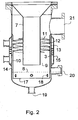
- the construction of the separating device is shown in Figure 2 .
- the evaporation product enters downpipe 7.
- the upper end of the downpipe is shaped as a funnel in order to maintain the same outer diameter in the separator as in the evaporator.
- the evaporation product emerges from the lower end of the downpipe, encounters the water surface 8 on the bottom of the device, and turns 180 ° to enter the annular rising channel 9 between the downpipe and intermediate shell 10.
- Spiral fins 11 form a spiral path 12 for the evaporation product.
- the spiral movement of the evaporation product causes centrifugal force which force water droplets in the product to the periphery of path 12, Foreign matter present in the evaporation product may act as nuclei for condensation, and this phenomenon thus enhances the transport of this matter to the periphery of the spiral path. Pure, dry steam leaves spiral path 12 and exits the device at connection 21.
- At least one opening 13 is provided the intermediate shell 10 to allow droplets to enter space 3 between the intermediate shell and outer shell 14.
- Outer shell 14 is provided with a temperature control jacket 15. As this jacket is used to cool the inner surface of shell 14, steam in space 3 condense on said inner surface and form a descending water film. The condensation ensures, that no backflow occurs into spiral path 12 through openings 13.
- a suitable number of openings 13 of an appropriate shape may be provided Droplets and impurities driven to the inner wall of shell 10 by centrifugal force pass through the openings, and are carried to the cooled inner wall of outer shell 14 by the radial outward stream caused by condensation of steam.
- the openings may be designed as vertical slits in the outer periphery of the spiral path, i.e. in shell 10.
- One or more slits running in parallel to the spiral fins is also possible, as well as circular, oval or other shapes of opening; possibly arranged with edges enhancing the capture of droplets in circular motion along the spiral path.
- the surface of the pool of water formed from condensate and droplets is kept above lower edge 17 of intermediate shell 10; thus flow of evaporation product is possible only along the route described.
- Spacer indents 18 may be provided to center the lower end of the intermediate shell.
- a reject flow rich in impurities is withdrawn at 19.
- a sight glass 20 may be provided to monitor the water level.
- Figure 3 shows a top view of the unit of Figures with the top cut off at the level of the temperature control jacket.
- the large arrows indicate the circular movement of the evaporation product in the spiral path.
- Openings 13 are shown with baffles 16 to enhance the capture of droplets and impurities carried to the periphery of the path, as shown by the small arrows
- the temperature of outer shell 14 is be controlled to effect a suitable rate of condensation.
- feed water can be used in jacket 15.
- the amount of reject water formed can be controlled according to load and purity requirements.
- FIG. 4 shows a system for the production of pure steam.
- feed water is provided by means of pump 23.
- the evaporator comprises a separating unit 24 according to the present invention.
- Heating steam enters through valve 25, while condensate leaves by connection 5 (tubing not shown).
- Pure steam leaves the evaporator via line 27 and control valve 28, and enters the distribution network which includes pure steam line valves 29 and pure steam traps 30.
- Reject water enriched in impurities leaves separating unit 24 through line 31.
- Feed and return lines 32,33 for the temperature control jacket are provided.
- the inner structure was integrated with the pressure vessel shell, and could not be altered without going through the tedious procedure involved with pressure vessel construction.
- the inner parts and/or details thereof can be manufactured from any required, corrosion-proof materials, and may be removed for cleaning and inspection.
- Such materials include fluorocarbon polymers, ceramic materials and special steels or other metals which need not be suited for being joined by welding to the pressure vessel shell.
- the inner parts may also be exchanged to suit different throughputs and purity requirements.
Landscapes
- Chemical & Material Sciences (AREA)
- Chemical Kinetics & Catalysis (AREA)
- Vaporization, Distillation, Condensation, Sublimation, And Cold Traps (AREA)
- Heat Treatment Of Water, Waste Water Or Sewage (AREA)
- Separating Particles In Gases By Inertia (AREA)
- Hydrogen, Water And Hydrids (AREA)
- Electrical Discharge Machining, Electrochemical Machining, And Combined Machining (AREA)
- Transition And Organic Metals Composition Catalysts For Addition Polymerization (AREA)
- Body Structure For Vehicles (AREA)
- Cleaning Or Drying Semiconductors (AREA)
Abstract
Description
- The invention relates to the production of highly pure steam for special purposes. Particularly, the invention relates to the production of pure steam using a falling-film evaporator and rising channels for separating water droplets and impurities.
- Highly purified steam is required for various medical purposes, such as production of pharmaceuticals, demanding sterilization applications and production of water for injection. A method and device for production of such steam are disclosed in
US patent 3,875,017 . A falling film evaporator as disclosed therein comprises a vertical bundle of evaporation tubes enclosed into a heating jacket, which in turn is enclosed by an outer shell so that an annular space is formed between the heating jacket and the outer shell. Water fed into the evaporating tubes at their upper end flows down the inner surface of the tubes, thereby evaporating and forming steam, which emerges at the lower ends of the tube bundle. The flow of steam makes a 180° turn and flows upwards in the space between the heating jacket and the outer shell. Fins forming a spiral path are attached to the outer surface of the heating jacket, leaving a narrow gap between their edges and the inner surface of the shell. The steam flowing upwards is forced into a spiraling path, whereby water droplets in the evaporation product are driven towards the outer shell by centrifugal force. - The droplets adhere to the outer shell wall and form a film of water flowing downwards and finally forming a pool of liquid at the bottom of the device. From there, a stream of water proportional to the amount of pure steam produced is withdrawn as a reject stream. As the water phase in the evaporation product tends to be rich in impurities, these are enriched into the reject stream. From above the spiral path, pure steam is led to the consumption points or to a condenser for producing highly pure water.
- A variation of the device is disclosed in
US patent 5,983,842 . The evaporation product emerging from the lower ends of the tube bundle is brought into a circular motion by baffle fins at the bottom of the device, and the rising space narrows towards the top. The spiral path is arranged into the top of the rising space and it is closed, i.e. the fins reach the inner surface of the outer shell. No downwards-flowing reject phase is formed, but the droplets accelerate and are collected into an annular channel above the spiral path. A separate tube returns the resulting water phase to the bottom of the device. - An improved method and device have been invented for enhancing the separation of water droplets and impurities in the rising channel of a falling film evaporator for production of highly pure steam. A further object of the invention is a system for the production and distribution of pure steam, the system comprising the improved device.
- The device according to the present invention is used together with a vertical tube bundle with a heating jacket, i.e. a conventional type of falling film evaporator. The evaporation product emerges from the lower end of the tube bundle.
- According to the invention, the device for separating water droplets and impurities from the evaporation product comprises a length of downpipe through which the evaporation products initially flows before making a 180 ° turn and entering a rising channel between the outer surface of the downpipe and the inner surface of an intermediate shell. The downpipe may be initially tapered, forming a funnel.
- Spiral fins adapted in the upper part of the rising channel set the evaporation product in an upwardly spiraling, circular motion. According to the present invention, the intermediate shell is provided with at least one opening or outlet slit, allowing droplets carried by centrifugal force to the periphery of the spiral path to leave. Outside the openings, a cooled surface in the outer shell ensures, that condensation of steam takes place.
- Steam condensing on the inner surface of the outer shell causes a radial outward stream carrying steam, water droplets and impurities to the said inner surface. A water film is formed which flows down said surface in the space between the outer and intermediate shells. A pool of water is formed on the bottom of the unit, submerging the lower edge of the intermediate shell. A controlled stream of reject water is withdrawn from the pool. The pure, dry steam leaving the upper end of the spiral path exits the device.
- The invention enables the use of detachable inner parts in the steam generator, which provides for easy maintenance and cleaning, as the whole of the apparatus need not be pressure vessel certified.
- The invention is disclosed in detail below with reference to the accompanying drawings, wherein
-
Figure 1 shows a steam generator comprising a falling film evaporator provided with a separator unit according to the present invention, -
Figure 2 shows details of a separator unit according to the present invention, -
Figure 3 is a top view section of the unit offing. 2, and -
Figure 4 shows a system for the production of pure steam, which system includes the device ofFigure 2 . -
Figure 1 shows a shell-and-tube heat exchanger arranged in a vertical position to form a falling film evaporator. Evaporation tubes 1 are enclosed in ajacket 2, through which a heating medium is conducted via in- andoutlets inlet 6. At the lower end of the evaporator, a separating device according to the invention is connected. - The construction of the separating device is shown in
Figure 2 . The evaporation product entersdownpipe 7. In the embodiment shown, the upper end of the downpipe is shaped as a funnel in order to maintain the same outer diameter in the separator as in the evaporator. The evaporation product emerges from the lower end of the downpipe, encounters the water surface 8 on the bottom of the device, and turns 180 ° to enter the annular rising channel 9 between the downpipe andintermediate shell 10. Spiral fins 11 form aspiral path 12 for the evaporation product. - The spiral movement of the evaporation product causes centrifugal force which force water droplets in the product to the periphery of
path 12, Foreign matter present in the evaporation product may act as nuclei for condensation, and this phenomenon thus enhances the transport of this matter to the periphery of the spiral path. Pure, dry steam leavesspiral path 12 and exits the device atconnection 21. - At least one
opening 13 is provided theintermediate shell 10 to allow droplets to enterspace 3 between the intermediate shell andouter shell 14.Outer shell 14 is provided with atemperature control jacket 15. As this jacket is used to cool the inner surface ofshell 14, steam inspace 3 condense on said inner surface and form a descending water film. The condensation ensures, that no backflow occurs intospiral path 12 throughopenings 13. A suitable number ofopenings 13 of an appropriate shape may be provided Droplets and impurities driven to the inner wall ofshell 10 by centrifugal force pass through the openings, and are carried to the cooled inner wall ofouter shell 14 by the radial outward stream caused by condensation of steam. - The openings may be designed as vertical slits in the outer periphery of the spiral path, i.e. in
shell 10. One or more slits running in parallel to the spiral fins is also possible, as well as circular, oval or other shapes of opening; possibly arranged with edges enhancing the capture of droplets in circular motion along the spiral path. - The surface of the pool of water formed from condensate and droplets is kept above
lower edge 17 ofintermediate shell 10; thus flow of evaporation product is possible only along the route described.Spacer indents 18 may be provided to center the lower end of the intermediate shell. A reject flow rich in impurities is withdrawn at 19. Asight glass 20 may be provided to monitor the water level. -
Figure 3 shows a top view of the unit of Figures with the top cut off at the level of the temperature control jacket. The large arrows indicate the circular movement of the evaporation product in the spiral path.Openings 13 are shown withbaffles 16 to enhance the capture of droplets and impurities carried to the periphery of the path, as shown by the small arrows - Preferably, the temperature of
outer shell 14 is be controlled to effect a suitable rate of condensation. To conserve energy, feed water can be used injacket 15. By means of this temperature control, the amount of reject water formed can be controlled according to load and purity requirements. -
Figure 4 shows a system for the production of pure steam. To a fallingfilm evaporator 22, feed water is provided by means ofpump 23. The evaporator comprises a separatingunit 24 according to the present invention. Heating steam enters throughvalve 25, while condensate leaves by connection 5 (tubing not shown). Pure steam leaves the evaporator vialine 27 andcontrol valve 28, and enters the distribution network which includes puresteam line valves 29 and pure steam traps 30. Reject water enriched in impurities leaves separatingunit 24 throughline 31. Feed and returnlines - In prior art devices, corrosion and the closed structure of the separator units caused problems as the steam paths were not easily accessible The inner structure was integrated with the pressure vessel shell, and could not be altered without going through the tedious procedure involved with pressure vessel construction. In the disclosed device according to the invention, only the outer shell part must fulfil pressure vessel requirements. Accordingly, the inner parts and/or details thereof can be manufactured from any required, corrosion-proof materials, and may be removed for cleaning and inspection. Such materials include fluorocarbon polymers, ceramic materials and special steels or other metals which need not be suited for being joined by welding to the pressure vessel shell. The inner parts may also be exchanged to suit different throughputs and purity requirements.
Claims (6)
- A method for purifying an evaporation product to produce pure steam, wherein the evaporation product is set in a spiraling rotational motion to separate droplets by centrifugal force, characterized by
providing an evaporation product by means of a falling film evaporator (22)
conducting said evaporation product into an annular rising channel comprising spiral fins (11) forming a spiral path (12),
providing at least one opening (13) in the outer surface of said spiral path
collecting droplets and impurities on an actively cooled surface outside said at least one opening. - The method according to claim 1, characterized by the temperature of the cooled surface being controlled by means of water used as feed water.
- A falling film evaporator comprising a device for the purification of an evaporation product to produce pure steam having- an outer shell (14),- an annular rising channel (9) comprising spiral fins (11) forming a spiral path (12) between an intermediate shell (10) and a downpipe (7)- a space (16) between the intermediate shell (10) and the outer shell (14)- at least one opening (13) in the intermediate shell (10),- a temperature control jacket (15) for cooling a surface on the outer shell (14) outside said at least one opening(s) (13),
characterised by being connected to the lower end of the falling film evaporator (22) such that the evaporation product can first enter the downpipe (7) and subsequently the annular rising channel (9). - The device according to claim 3, characterized by the openings (13) being vertical slits.
- The device according to claim 3 or 4, characterized by at least one detail within the pressure vessel shell being detachable.
- The device according to any claim 3 - 5, characterized by at least one detail within the pressure vessel shell being made from a corrosive resistant material different from that of the pressure vessel shell.
Applications Claiming Priority (3)
| Application Number | Priority Date | Filing Date | Title |
|---|---|---|---|
| FI20002104A FI112781B (en) | 2000-09-25 | 2000-09-25 | Process and apparatus for producing pure steam |
| FI20002104 | 2000-09-25 | ||
| PCT/FI2001/000810 WO2002024299A1 (en) | 2000-09-25 | 2001-09-19 | Method and device for the production of pure steam |
Publications (2)
| Publication Number | Publication Date |
|---|---|
| EP1324810A1 EP1324810A1 (en) | 2003-07-09 |
| EP1324810B1 true EP1324810B1 (en) | 2010-02-10 |
Family
ID=8559150
Family Applications (1)
| Application Number | Title | Priority Date | Filing Date |
|---|---|---|---|
| EP01969828A Expired - Lifetime EP1324810B1 (en) | 2000-09-25 | 2001-09-19 | Method and device for the production of pure steam |
Country Status (11)
| Country | Link |
|---|---|
| US (1) | US6656327B2 (en) |
| EP (1) | EP1324810B1 (en) |
| JP (1) | JP5483226B2 (en) |
| CN (1) | CN1222338C (en) |
| AT (1) | ATE457191T1 (en) |
| AU (2) | AU8996501A (en) |
| CA (1) | CA2422943A1 (en) |
| DE (1) | DE60141279D1 (en) |
| ES (1) | ES2339221T3 (en) |
| FI (1) | FI112781B (en) |
| WO (1) | WO2002024299A1 (en) |
Families Citing this family (35)
| Publication number | Priority date | Publication date | Assignee | Title |
|---|---|---|---|---|
| FI118374B (en) * | 2002-08-28 | 2007-10-31 | Steris Europe Inc | Process and apparatus for producing purified steam |
| FI115506B (en) | 2003-05-16 | 2005-05-31 | Steris Europe Inc | Method and apparatus for treating water |
| US7024104B2 (en) | 2003-05-16 | 2006-04-04 | Delaware Capital Formation, Inc. | Boilerless steamer apparatus |
| FI20030735L (en) * | 2003-05-16 | 2004-11-17 | Steris Europe Inc | Method and device for treating water |
| US8686188B2 (en) | 2003-07-04 | 2014-04-01 | Jiangsu Sinorgchem Technology Co., Ltd. | Process for preparing 4-aminodiphenylamine |
| US8486223B2 (en) * | 2003-07-04 | 2013-07-16 | Jiangsu Sinorgchem Technology Co., Ltd. | Falling film evaporator |
| JP4500302B2 (en) * | 2003-07-04 | 2010-07-14 | チアンス・シノケム・テクノロジー・カンパニー・リミテッド | Method for producing 4-aminodiphenylamine |
| KR200360077Y1 (en) * | 2004-06-14 | 2004-08-25 | 쿠쿠전자주식회사 | Spray assembly for humidifier |
| US7559965B2 (en) | 2005-01-25 | 2009-07-14 | Samsung Gwangju Electronics Co., Ltd. | Cyclonic separating apparatus for vacuum cleaner which is capable of separately collecting water from dust |
| US7802423B2 (en) * | 2006-08-21 | 2010-09-28 | General Electric Company | Condenser unit for NOx emission reduction system |
| CN102259029B (en) | 2010-05-24 | 2014-12-10 | 江苏圣奥化学科技有限公司 | Solid alkali catalyst |
| PT2583042T (en) * | 2010-06-21 | 2017-07-25 | Cft Spa | Concentration plant with differently working sections. |
| CN103180022B (en) | 2010-07-21 | 2016-02-17 | 阿奎巴克技术公司 | Distiller with applicator for thin film evaporation and scraper for deposit removal |
| JP5808046B2 (en) * | 2011-09-22 | 2015-11-10 | 株式会社イシン技研 | Multi-effect can-type distilled water production equipment |
| CN102515296A (en) * | 2011-12-30 | 2012-06-27 | 河北巴瑞斯科技发展有限公司 | Film-rising evaporation device |
| CN102424441A (en) * | 2011-12-30 | 2012-04-25 | 河北巴瑞斯科技发展有限公司 | Steam-water separator for climbing film type distilled water machine |
| RU2488427C1 (en) * | 2012-01-25 | 2013-07-27 | Федеральное государственное бюджетное учреждение науки Институт теплофизики им. С.С. Кутателадзе Сибирского отделения Российской академии наук (ИТ СО РАН) | Separation of low-boiling component from mix of vapors and device to this end |
| US20140158514A1 (en) * | 2012-12-07 | 2014-06-12 | Advanced Water Recovery, Llc | Methods of separating salts and solvents from water |
| CN103028292A (en) * | 2012-12-25 | 2013-04-10 | 张甲贵 | Gas-liquid separator |
| JP5991675B2 (en) * | 2013-08-28 | 2016-09-14 | 三菱重工オートモーティブサーマルシステムズ株式会社 | Oil separator and compressor provided with the same |
| EP2891861B1 (en) * | 2014-01-07 | 2016-07-20 | Rinheat Oy | Vertical straight tube countercurrent condenser |
| US9783431B2 (en) * | 2014-05-28 | 2017-10-10 | Katz Water Tech, Llc | Apparatus and method to remove contaminates from a fluid |
| RU2618870C1 (en) * | 2016-03-28 | 2017-05-11 | Федеральное государственное бюджетное образовательное учреждение высшего профессионального образования "Уфимский государственный нефтяной технический университет" | Device for oil product dehydration from sediment ponds and sludge tanks |
| US11142467B2 (en) * | 2016-08-31 | 2021-10-12 | VMACTEK Pty Ltd | Evaporator |
| US10265651B2 (en) | 2016-11-14 | 2019-04-23 | Hamilton Sundstrand Corporation | Compact water extractor |
| US10864482B2 (en) | 2017-08-24 | 2020-12-15 | Katz Water Tech, Llc | Apparatus system and method to separate brine from water |
| US11034605B2 (en) | 2018-03-29 | 2021-06-15 | Katz Water Tech, Llc | Apparatus system and method to extract minerals and metals from water |
| CN107830660A (en) * | 2017-12-04 | 2018-03-23 | 珠海格力电器股份有限公司 | Vertical evaporator, gas-liquid separation method, refrigeration system and air conditioner |
| US11389745B2 (en) * | 2019-12-13 | 2022-07-19 | Exxon Mobil Technology and Engineering Company | Liquid de-entrainment in heat exchange equipment |
| CN111467822B (en) * | 2019-12-23 | 2021-11-26 | 南通熠能精细石墨科技有限公司 | Double-effect combined inverted cone graphite falling film evaporator |
| KR200494642Y1 (en) * | 2021-08-26 | 2021-11-19 | (주)마스터이엔지 | Distillation type extraction apparatus for vapor |
| CN113932490B (en) * | 2021-11-11 | 2025-03-14 | 珠海格力电器股份有限公司 | Heat exchangers and air conditioning units |
| JP2023171092A (en) * | 2022-05-20 | 2023-12-01 | 株式会社エプシロン | Mist separation and collection device |
| CN116370997A (en) * | 2023-03-20 | 2023-07-04 | 广东万冠制药设备科技有限公司 | A vapor-liquid separation device for pure steam generator |
| KR102908840B1 (en) * | 2024-12-13 | 2026-01-06 | 박종현 | Multi Effect W.F.I Distiller System |
Citations (1)
| Publication number | Priority date | Publication date | Assignee | Title |
|---|---|---|---|---|
| DE870243C (en) * | 1951-03-30 | 1953-03-12 | Phrix Werke Ag | Method and device for separating liquids from gas mixtures |
Family Cites Families (21)
| Publication number | Priority date | Publication date | Assignee | Title |
|---|---|---|---|---|
| US3004590A (en) * | 1957-04-15 | 1961-10-17 | Curt F Rosenblad | Multiple effect evaporators |
| FR1175990A (en) * | 1957-06-13 | 1959-04-03 | vertical tube bundle evaporator | |
| FI47083C (en) | 1971-04-22 | 1973-09-10 | Huhta-Koivisto | Distillation method and apparatus |
| US4059419A (en) * | 1972-10-02 | 1977-11-22 | Leon Irving Ross | Vortex nucleation scrubbing method and apparatus |
| JPS572041B2 (en) * | 1972-10-23 | 1982-01-13 | ||
| CH586567A5 (en) * | 1974-10-09 | 1977-04-15 | Luwa Ag | |
| JPS5474380U (en) * | 1977-11-07 | 1979-05-26 | ||
| CH643149A5 (en) * | 1979-07-10 | 1984-05-30 | Luwa Ag | METHOD AND DEVICE FOR CONTINUOUS THERMAL TREATMENT OF PUMPABLE SUBSTANCES IN A THIN LAYER. |
| US4375386A (en) * | 1981-05-07 | 1983-03-01 | The Badger Company, Inc. | Cyclonic entrainment separator for evaporator |
| JPS6046107U (en) * | 1983-09-08 | 1985-04-01 | オルガノ株式会社 | Gas-liquid separator |
| US4629481A (en) * | 1985-01-18 | 1986-12-16 | Westinghouse Electric Corp. | Low pressure drop modular centrifugal moisture separator |
| JPH0626332Y2 (en) * | 1987-10-16 | 1994-07-20 | 三菱重工業株式会社 | Exhaust gas mist removal device |
| DE3804245A1 (en) | 1988-02-11 | 1989-08-24 | Gea Wiegand Gmbh | Vaporiser unit |
| JPH062726Y2 (en) * | 1989-06-23 | 1994-01-26 | 住友軽金属工業株式会社 | Mist recovery device with twisted plate insertion tube |
| JPH03109663U (en) * | 1990-02-21 | 1991-11-11 | ||
| US5246541A (en) | 1991-05-14 | 1993-09-21 | A. Ahlstrom Corporation | Evaporator for liquid solutions |
| JPH08970Y2 (en) * | 1992-03-25 | 1996-01-17 | 住友軽金属工業株式会社 | Mist collection device |
| JP3388553B2 (en) | 1993-04-06 | 2003-03-24 | 株式会社日阪製作所 | Evaporator |
| US6059934A (en) * | 1997-04-07 | 2000-05-09 | Mobil Oil Corporation | Co-current contacting separation tray design and methods for using same |
| JP3707035B2 (en) | 1997-04-22 | 2005-10-19 | 株式会社イシン技研 | Vertical evaporator |
| JPH10328647A (en) * | 1997-06-03 | 1998-12-15 | Chiyoda Manufacturing Co Ltd | Apparatus for removing fine particle from steam generator for producing pure steam and distilled water |
-
2000
- 2000-09-25 FI FI20002104A patent/FI112781B/en active
-
2001
- 2001-09-19 JP JP2002528364A patent/JP5483226B2/en not_active Expired - Lifetime
- 2001-09-19 AU AU8996501A patent/AU8996501A/en active Pending
- 2001-09-19 CN CNB01816255XA patent/CN1222338C/en not_active Expired - Lifetime
- 2001-09-19 DE DE60141279T patent/DE60141279D1/en not_active Expired - Lifetime
- 2001-09-19 AT AT01969828T patent/ATE457191T1/en not_active IP Right Cessation
- 2001-09-19 WO PCT/FI2001/000810 patent/WO2002024299A1/en not_active Ceased
- 2001-09-19 CA CA002422943A patent/CA2422943A1/en not_active Abandoned
- 2001-09-19 EP EP01969828A patent/EP1324810B1/en not_active Expired - Lifetime
- 2001-09-19 ES ES01969828T patent/ES2339221T3/en not_active Expired - Lifetime
- 2001-09-19 AU AU2001289965A patent/AU2001289965B2/en not_active Ceased
- 2001-09-21 US US09/961,021 patent/US6656327B2/en not_active Expired - Lifetime
Patent Citations (1)
| Publication number | Priority date | Publication date | Assignee | Title |
|---|---|---|---|---|
| DE870243C (en) * | 1951-03-30 | 1953-03-12 | Phrix Werke Ag | Method and device for separating liquids from gas mixtures |
Also Published As
| Publication number | Publication date |
|---|---|
| WO2002024299A1 (en) | 2002-03-28 |
| EP1324810A1 (en) | 2003-07-09 |
| CN1222338C (en) | 2005-10-12 |
| ES2339221T3 (en) | 2010-05-18 |
| HK1060991A1 (en) | 2004-09-03 |
| CN1466479A (en) | 2004-01-07 |
| CA2422943A1 (en) | 2002-03-28 |
| FI112781B (en) | 2004-01-15 |
| DE60141279D1 (en) | 2010-03-25 |
| US6656327B2 (en) | 2003-12-02 |
| FI20002104A0 (en) | 2000-09-25 |
| JP5483226B2 (en) | 2014-05-07 |
| AU8996501A (en) | 2002-04-02 |
| FI20002104L (en) | 2002-03-26 |
| US20020038760A1 (en) | 2002-04-04 |
| JP2004508922A (en) | 2004-03-25 |
| ATE457191T1 (en) | 2010-02-15 |
| AU2001289965B2 (en) | 2006-12-14 |
Similar Documents
| Publication | Publication Date | Title |
|---|---|---|
| AU2001289965B2 (en) | Method and device for the production of pure steam | |
| AU2001289965A1 (en) | Method and device for the production of pure steam | |
| EP1534399B1 (en) | Method and device for the production of purified steam | |
| US4969507A (en) | Integral blow down concentrator with air-cooled surface condenser | |
| US5983842A (en) | Vertical evaporator | |
| JP2008168183A (en) | Vapor-liquid separator and water producing device | |
| AU2003255555B2 (en) | Method and device for the production of purified steam | |
| EP0530001A2 (en) | Multi-stage evaporation of liquid | |
| HK1060991B (en) | Method and device for the producition of pure steam | |
| SU1296231A1 (en) | Separator | |
| RU2424031C1 (en) | Film-type evaporator with thin-sheet flow | |
| SU969299A1 (en) | Froth-and-vortex apparatus | |
| US5003784A (en) | Apparatus and method of producing an ice slurry at the triple point of a solution | |
| EP4508026B1 (en) | A falling film heat exchanger | |
| SU1011185A1 (en) | Cyclone froth type scrubber | |
| TWI294304B (en) | Method and apparatus for collecting and redirecting liquid separated from a gaseous stream | |
| CN209530447U (en) | Gas phase organic matter in hydrogen chloride condenses demisting separator | |
| SU978894A1 (en) | Moisture separator | |
| PL176614B1 (en) | Mechanical film-type evaporator for thickening liquids readily forming foam | |
| WO1999043958A1 (en) | Oil cooler and separator assembly | |
| HK1092451A1 (en) | Method and device for treating water | |
| HK1092451B (en) | Method and device for treating water | |
| JP2002085903A (en) | Concentrator based on freezing of aqueous solution |
Legal Events
| Date | Code | Title | Description |
|---|---|---|---|
| PUAI | Public reference made under article 153(3) epc to a published international application that has entered the european phase |
Free format text: ORIGINAL CODE: 0009012 |
|
| 17P | Request for examination filed |
Effective date: 20030312 |
|
| AK | Designated contracting states |
Designated state(s): AT BE CH CY DE DK ES FI FR GB GR IE IT LI LU MC NL PT SE TR |
|
| AX | Request for extension of the european patent |
Extension state: AL LT LV MK RO SI |
|
| 17Q | First examination report despatched |
Effective date: 20070507 |
|
| GRAP | Despatch of communication of intention to grant a patent |
Free format text: ORIGINAL CODE: EPIDOSNIGR1 |
|
| GRAS | Grant fee paid |
Free format text: ORIGINAL CODE: EPIDOSNIGR3 |
|
| GRAA | (expected) grant |
Free format text: ORIGINAL CODE: 0009210 |
|
| AK | Designated contracting states |
Kind code of ref document: B1 Designated state(s): AT BE CH CY DE DK ES FI FR GB GR IE IT LI LU MC NL PT SE TR |
|
| REG | Reference to a national code |
Ref country code: GB Ref legal event code: FG4D |
|
| REG | Reference to a national code |
Ref country code: CH Ref legal event code: EP |
|
| REG | Reference to a national code |
Ref country code: IE Ref legal event code: FG4D |
|
| REF | Corresponds to: |
Ref document number: 60141279 Country of ref document: DE Date of ref document: 20100325 Kind code of ref document: P |
|
| REG | Reference to a national code |
Ref country code: ES Ref legal event code: FG2A Ref document number: 2339221 Country of ref document: ES Kind code of ref document: T3 |
|
| REG | Reference to a national code |
Ref country code: NL Ref legal event code: VDEP Effective date: 20100210 |
|
| PG25 | Lapsed in a contracting state [announced via postgrant information from national office to epo] |
Ref country code: PT Free format text: LAPSE BECAUSE OF FAILURE TO SUBMIT A TRANSLATION OF THE DESCRIPTION OR TO PAY THE FEE WITHIN THE PRESCRIBED TIME-LIMIT Effective date: 20100611 |
|
| PG25 | Lapsed in a contracting state [announced via postgrant information from national office to epo] |
Ref country code: FI Free format text: LAPSE BECAUSE OF FAILURE TO SUBMIT A TRANSLATION OF THE DESCRIPTION OR TO PAY THE FEE WITHIN THE PRESCRIBED TIME-LIMIT Effective date: 20100210 Ref country code: AT Free format text: LAPSE BECAUSE OF FAILURE TO SUBMIT A TRANSLATION OF THE DESCRIPTION OR TO PAY THE FEE WITHIN THE PRESCRIBED TIME-LIMIT Effective date: 20100210 |
|
| PG25 | Lapsed in a contracting state [announced via postgrant information from national office to epo] |
Ref country code: SE Free format text: LAPSE BECAUSE OF FAILURE TO SUBMIT A TRANSLATION OF THE DESCRIPTION OR TO PAY THE FEE WITHIN THE PRESCRIBED TIME-LIMIT Effective date: 20100210 Ref country code: NL Free format text: LAPSE BECAUSE OF FAILURE TO SUBMIT A TRANSLATION OF THE DESCRIPTION OR TO PAY THE FEE WITHIN THE PRESCRIBED TIME-LIMIT Effective date: 20100210 Ref country code: GR Free format text: LAPSE BECAUSE OF FAILURE TO SUBMIT A TRANSLATION OF THE DESCRIPTION OR TO PAY THE FEE WITHIN THE PRESCRIBED TIME-LIMIT Effective date: 20100511 Ref country code: CY Free format text: LAPSE BECAUSE OF FAILURE TO SUBMIT A TRANSLATION OF THE DESCRIPTION OR TO PAY THE FEE WITHIN THE PRESCRIBED TIME-LIMIT Effective date: 20100210 Ref country code: BE Free format text: LAPSE BECAUSE OF FAILURE TO SUBMIT A TRANSLATION OF THE DESCRIPTION OR TO PAY THE FEE WITHIN THE PRESCRIBED TIME-LIMIT Effective date: 20100210 |
|
| PGFP | Annual fee paid to national office [announced via postgrant information from national office to epo] |
Ref country code: IE Payment date: 20100917 Year of fee payment: 10 |
|
| PLBE | No opposition filed within time limit |
Free format text: ORIGINAL CODE: 0009261 |
|
| STAA | Information on the status of an ep patent application or granted ep patent |
Free format text: STATUS: NO OPPOSITION FILED WITHIN TIME LIMIT |
|
| 26N | No opposition filed |
Effective date: 20101111 |
|
| PG25 | Lapsed in a contracting state [announced via postgrant information from national office to epo] |
Ref country code: DK Free format text: LAPSE BECAUSE OF FAILURE TO SUBMIT A TRANSLATION OF THE DESCRIPTION OR TO PAY THE FEE WITHIN THE PRESCRIBED TIME-LIMIT Effective date: 20100210 |
|
| PG25 | Lapsed in a contracting state [announced via postgrant information from national office to epo] |
Ref country code: MC Free format text: LAPSE BECAUSE OF NON-PAYMENT OF DUE FEES Effective date: 20100930 |
|
| REG | Reference to a national code |
Ref country code: CH Ref legal event code: PL |
|
| PG25 | Lapsed in a contracting state [announced via postgrant information from national office to epo] |
Ref country code: LI Free format text: LAPSE BECAUSE OF NON-PAYMENT OF DUE FEES Effective date: 20100930 Ref country code: CH Free format text: LAPSE BECAUSE OF NON-PAYMENT OF DUE FEES Effective date: 20100930 |
|
| REG | Reference to a national code |
Ref country code: IE Ref legal event code: MM4A |
|
| PG25 | Lapsed in a contracting state [announced via postgrant information from national office to epo] |
Ref country code: IE Free format text: LAPSE BECAUSE OF NON-PAYMENT OF DUE FEES Effective date: 20110919 |
|
| PG25 | Lapsed in a contracting state [announced via postgrant information from national office to epo] |
Ref country code: LU Free format text: LAPSE BECAUSE OF NON-PAYMENT OF DUE FEES Effective date: 20100919 |
|
| PG25 | Lapsed in a contracting state [announced via postgrant information from national office to epo] |
Ref country code: TR Free format text: LAPSE BECAUSE OF FAILURE TO SUBMIT A TRANSLATION OF THE DESCRIPTION OR TO PAY THE FEE WITHIN THE PRESCRIBED TIME-LIMIT Effective date: 20100210 |
|
| REG | Reference to a national code |
Ref country code: FR Ref legal event code: PLFP Year of fee payment: 16 |
|
| REG | Reference to a national code |
Ref country code: FR Ref legal event code: PLFP Year of fee payment: 17 |
|
| REG | Reference to a national code |
Ref country code: FR Ref legal event code: PLFP Year of fee payment: 18 |
|
| PGFP | Annual fee paid to national office [announced via postgrant information from national office to epo] |
Ref country code: FR Payment date: 20200925 Year of fee payment: 20 Ref country code: GB Payment date: 20200928 Year of fee payment: 20 Ref country code: DE Payment date: 20200929 Year of fee payment: 20 |
|
| PGFP | Annual fee paid to national office [announced via postgrant information from national office to epo] |
Ref country code: IT Payment date: 20200923 Year of fee payment: 20 |
|
| PGFP | Annual fee paid to national office [announced via postgrant information from national office to epo] |
Ref country code: ES Payment date: 20201001 Year of fee payment: 20 |
|
| REG | Reference to a national code |
Ref country code: DE Ref legal event code: R071 Ref document number: 60141279 Country of ref document: DE |
|
| REG | Reference to a national code |
Ref country code: GB Ref legal event code: PE20 Expiry date: 20210918 |
|
| PG25 | Lapsed in a contracting state [announced via postgrant information from national office to epo] |
Ref country code: GB Free format text: LAPSE BECAUSE OF EXPIRATION OF PROTECTION Effective date: 20210918 |
|
| REG | Reference to a national code |
Ref country code: ES Ref legal event code: FD2A Effective date: 20211227 |
|
| PG25 | Lapsed in a contracting state [announced via postgrant information from national office to epo] |
Ref country code: ES Free format text: LAPSE BECAUSE OF EXPIRATION OF PROTECTION Effective date: 20210920 |