EP1324411A2 - Composite material for fuel cell separator molding and production method thereof, and fuel cell separator which uses the composite material and production method thereof - Google Patents
Composite material for fuel cell separator molding and production method thereof, and fuel cell separator which uses the composite material and production method thereof Download PDFInfo
- Publication number
- EP1324411A2 EP1324411A2 EP02028789A EP02028789A EP1324411A2 EP 1324411 A2 EP1324411 A2 EP 1324411A2 EP 02028789 A EP02028789 A EP 02028789A EP 02028789 A EP02028789 A EP 02028789A EP 1324411 A2 EP1324411 A2 EP 1324411A2
- Authority
- EP
- European Patent Office
- Prior art keywords
- resin
- fuel cell
- composite material
- cell separator
- molding according
- Prior art date
- Legal status (The legal status is an assumption and is not a legal conclusion. Google has not performed a legal analysis and makes no representation as to the accuracy of the status listed.)
- Withdrawn
Links
Images

Classifications
-
- H—ELECTRICITY
- H01—ELECTRIC ELEMENTS
- H01M—PROCESSES OR MEANS, e.g. BATTERIES, FOR THE DIRECT CONVERSION OF CHEMICAL ENERGY INTO ELECTRICAL ENERGY
- H01M8/00—Fuel cells; Manufacture thereof
- H01M8/02—Details
- H01M8/0202—Collectors; Separators, e.g. bipolar separators; Interconnectors
- H01M8/023—Porous and characterised by the material
- H01M8/0241—Composites
- H01M8/0243—Composites in the form of mixtures
-
- C—CHEMISTRY; METALLURGY
- C04—CEMENTS; CONCRETE; ARTIFICIAL STONE; CERAMICS; REFRACTORIES
- C04B—LIME, MAGNESIA; SLAG; CEMENTS; COMPOSITIONS THEREOF, e.g. MORTARS, CONCRETE OR LIKE BUILDING MATERIALS; ARTIFICIAL STONE; CERAMICS; REFRACTORIES; TREATMENT OF NATURAL STONE
- C04B35/00—Shaped ceramic products characterised by their composition; Ceramics compositions; Processing powders of inorganic compounds preparatory to the manufacturing of ceramic products
- C04B35/515—Shaped ceramic products characterised by their composition; Ceramics compositions; Processing powders of inorganic compounds preparatory to the manufacturing of ceramic products based on non-oxide ceramics
- C04B35/52—Shaped ceramic products characterised by their composition; Ceramics compositions; Processing powders of inorganic compounds preparatory to the manufacturing of ceramic products based on non-oxide ceramics based on carbon, e.g. graphite
-
- C—CHEMISTRY; METALLURGY
- C04—CEMENTS; CONCRETE; ARTIFICIAL STONE; CERAMICS; REFRACTORIES
- C04B—LIME, MAGNESIA; SLAG; CEMENTS; COMPOSITIONS THEREOF, e.g. MORTARS, CONCRETE OR LIKE BUILDING MATERIALS; ARTIFICIAL STONE; CERAMICS; REFRACTORIES; TREATMENT OF NATURAL STONE
- C04B35/00—Shaped ceramic products characterised by their composition; Ceramics compositions; Processing powders of inorganic compounds preparatory to the manufacturing of ceramic products
- C04B35/515—Shaped ceramic products characterised by their composition; Ceramics compositions; Processing powders of inorganic compounds preparatory to the manufacturing of ceramic products based on non-oxide ceramics
- C04B35/52—Shaped ceramic products characterised by their composition; Ceramics compositions; Processing powders of inorganic compounds preparatory to the manufacturing of ceramic products based on non-oxide ceramics based on carbon, e.g. graphite
- C04B35/522—Graphite
-
- C—CHEMISTRY; METALLURGY
- C04—CEMENTS; CONCRETE; ARTIFICIAL STONE; CERAMICS; REFRACTORIES
- C04B—LIME, MAGNESIA; SLAG; CEMENTS; COMPOSITIONS THEREOF, e.g. MORTARS, CONCRETE OR LIKE BUILDING MATERIALS; ARTIFICIAL STONE; CERAMICS; REFRACTORIES; TREATMENT OF NATURAL STONE
- C04B35/00—Shaped ceramic products characterised by their composition; Ceramics compositions; Processing powders of inorganic compounds preparatory to the manufacturing of ceramic products
- C04B35/622—Forming processes; Processing powders of inorganic compounds preparatory to the manufacturing of ceramic products
- C04B35/626—Preparing or treating the powders individually or as batches ; preparing or treating macroscopic reinforcing agents for ceramic products, e.g. fibres; mechanical aspects section B
- C04B35/63—Preparing or treating the powders individually or as batches ; preparing or treating macroscopic reinforcing agents for ceramic products, e.g. fibres; mechanical aspects section B using additives specially adapted for forming the products, e.g.. binder binders
- C04B35/632—Organic additives
- C04B35/634—Polymers
- C04B35/63404—Polymers obtained by reactions only involving carbon-to-carbon unsaturated bonds
- C04B35/63432—Polystyrenes
-
- H—ELECTRICITY
- H01—ELECTRIC ELEMENTS
- H01M—PROCESSES OR MEANS, e.g. BATTERIES, FOR THE DIRECT CONVERSION OF CHEMICAL ENERGY INTO ELECTRICAL ENERGY
- H01M8/00—Fuel cells; Manufacture thereof
- H01M8/02—Details
- H01M8/0202—Collectors; Separators, e.g. bipolar separators; Interconnectors
- H01M8/0204—Non-porous and characterised by the material
- H01M8/0223—Composites
- H01M8/0226—Composites in the form of mixtures
-
- H—ELECTRICITY
- H01—ELECTRIC ELEMENTS
- H01M—PROCESSES OR MEANS, e.g. BATTERIES, FOR THE DIRECT CONVERSION OF CHEMICAL ENERGY INTO ELECTRICAL ENERGY
- H01M8/00—Fuel cells; Manufacture thereof
- H01M8/02—Details
- H01M8/0202—Collectors; Separators, e.g. bipolar separators; Interconnectors
- H01M8/0204—Non-porous and characterised by the material
- H01M8/0223—Composites
- H01M8/0228—Composites in the form of layered or coated products
-
- C—CHEMISTRY; METALLURGY
- C04—CEMENTS; CONCRETE; ARTIFICIAL STONE; CERAMICS; REFRACTORIES
- C04B—LIME, MAGNESIA; SLAG; CEMENTS; COMPOSITIONS THEREOF, e.g. MORTARS, CONCRETE OR LIKE BUILDING MATERIALS; ARTIFICIAL STONE; CERAMICS; REFRACTORIES; TREATMENT OF NATURAL STONE
- C04B2235/00—Aspects relating to ceramic starting mixtures or sintered ceramic products
- C04B2235/02—Composition of constituents of the starting material or of secondary phases of the final product
- C04B2235/30—Constituents and secondary phases not being of a fibrous nature
- C04B2235/42—Non metallic elements added as constituents or additives, e.g. sulfur, phosphor, selenium or tellurium
- C04B2235/422—Carbon
- C04B2235/424—Carbon black
-
- C—CHEMISTRY; METALLURGY
- C04—CEMENTS; CONCRETE; ARTIFICIAL STONE; CERAMICS; REFRACTORIES
- C04B—LIME, MAGNESIA; SLAG; CEMENTS; COMPOSITIONS THEREOF, e.g. MORTARS, CONCRETE OR LIKE BUILDING MATERIALS; ARTIFICIAL STONE; CERAMICS; REFRACTORIES; TREATMENT OF NATURAL STONE
- C04B2235/00—Aspects relating to ceramic starting mixtures or sintered ceramic products
- C04B2235/02—Composition of constituents of the starting material or of secondary phases of the final product
- C04B2235/30—Constituents and secondary phases not being of a fibrous nature
- C04B2235/42—Non metallic elements added as constituents or additives, e.g. sulfur, phosphor, selenium or tellurium
- C04B2235/422—Carbon
- C04B2235/425—Graphite
-
- C—CHEMISTRY; METALLURGY
- C04—CEMENTS; CONCRETE; ARTIFICIAL STONE; CERAMICS; REFRACTORIES
- C04B—LIME, MAGNESIA; SLAG; CEMENTS; COMPOSITIONS THEREOF, e.g. MORTARS, CONCRETE OR LIKE BUILDING MATERIALS; ARTIFICIAL STONE; CERAMICS; REFRACTORIES; TREATMENT OF NATURAL STONE
- C04B2235/00—Aspects relating to ceramic starting mixtures or sintered ceramic products
- C04B2235/02—Composition of constituents of the starting material or of secondary phases of the final product
- C04B2235/50—Constituents or additives of the starting mixture chosen for their shape or used because of their shape or their physical appearance
- C04B2235/52—Constituents or additives characterised by their shapes
- C04B2235/5208—Fibers
- C04B2235/5216—Inorganic
- C04B2235/524—Non-oxidic, e.g. borides, carbides, silicides or nitrides
- C04B2235/5248—Carbon, e.g. graphite
-
- C—CHEMISTRY; METALLURGY
- C04—CEMENTS; CONCRETE; ARTIFICIAL STONE; CERAMICS; REFRACTORIES
- C04B—LIME, MAGNESIA; SLAG; CEMENTS; COMPOSITIONS THEREOF, e.g. MORTARS, CONCRETE OR LIKE BUILDING MATERIALS; ARTIFICIAL STONE; CERAMICS; REFRACTORIES; TREATMENT OF NATURAL STONE
- C04B2235/00—Aspects relating to ceramic starting mixtures or sintered ceramic products
- C04B2235/60—Aspects relating to the preparation, properties or mechanical treatment of green bodies or pre-forms
- C04B2235/608—Green bodies or pre-forms with well-defined density
-
- C—CHEMISTRY; METALLURGY
- C04—CEMENTS; CONCRETE; ARTIFICIAL STONE; CERAMICS; REFRACTORIES
- C04B—LIME, MAGNESIA; SLAG; CEMENTS; COMPOSITIONS THEREOF, e.g. MORTARS, CONCRETE OR LIKE BUILDING MATERIALS; ARTIFICIAL STONE; CERAMICS; REFRACTORIES; TREATMENT OF NATURAL STONE
- C04B2235/00—Aspects relating to ceramic starting mixtures or sintered ceramic products
- C04B2235/60—Aspects relating to the preparation, properties or mechanical treatment of green bodies or pre-forms
- C04B2235/61—Mechanical properties, e.g. fracture toughness, hardness, Young's modulus or strength
-
- H—ELECTRICITY
- H01—ELECTRIC ELEMENTS
- H01M—PROCESSES OR MEANS, e.g. BATTERIES, FOR THE DIRECT CONVERSION OF CHEMICAL ENERGY INTO ELECTRICAL ENERGY
- H01M8/00—Fuel cells; Manufacture thereof
- H01M8/02—Details
- H01M8/0202—Collectors; Separators, e.g. bipolar separators; Interconnectors
- H01M8/0204—Non-porous and characterised by the material
- H01M8/0221—Organic resins; Organic polymers
-
- Y—GENERAL TAGGING OF NEW TECHNOLOGICAL DEVELOPMENTS; GENERAL TAGGING OF CROSS-SECTIONAL TECHNOLOGIES SPANNING OVER SEVERAL SECTIONS OF THE IPC; TECHNICAL SUBJECTS COVERED BY FORMER USPC CROSS-REFERENCE ART COLLECTIONS [XRACs] AND DIGESTS
- Y02—TECHNOLOGIES OR APPLICATIONS FOR MITIGATION OR ADAPTATION AGAINST CLIMATE CHANGE
- Y02E—REDUCTION OF GREENHOUSE GAS [GHG] EMISSIONS, RELATED TO ENERGY GENERATION, TRANSMISSION OR DISTRIBUTION
- Y02E60/00—Enabling technologies; Technologies with a potential or indirect contribution to GHG emissions mitigation
- Y02E60/30—Hydrogen technology
- Y02E60/50—Fuel cells
-
- Y—GENERAL TAGGING OF NEW TECHNOLOGICAL DEVELOPMENTS; GENERAL TAGGING OF CROSS-SECTIONAL TECHNOLOGIES SPANNING OVER SEVERAL SECTIONS OF THE IPC; TECHNICAL SUBJECTS COVERED BY FORMER USPC CROSS-REFERENCE ART COLLECTIONS [XRACs] AND DIGESTS
- Y02—TECHNOLOGIES OR APPLICATIONS FOR MITIGATION OR ADAPTATION AGAINST CLIMATE CHANGE
- Y02P—CLIMATE CHANGE MITIGATION TECHNOLOGIES IN THE PRODUCTION OR PROCESSING OF GOODS
- Y02P70/00—Climate change mitigation technologies in the production process for final industrial or consumer products
- Y02P70/50—Manufacturing or production processes characterised by the final manufactured product
Definitions
- This invention relates to a composite material for fuel cell separator molding and a production method thereof, and a fuel cell separator which uses the composite material and a production method thereof.
- a composite material for fuel cell separator molding for use in the production of a fuel cell separator having both of excellent mechanical characteristics and electric characteristics, and a production method thereof, and a fuel cell separator which uses the composite material and a production method thereof.
- electrolytes are interposed between porous positive and negative electrode plates, and scores to hundreds of cells arranged with flat separators having gas barrier property and conductivity are laminated on both outer sides of the plates, and its typical examples include a ribbed electrode system in which grooves as channels for reaction gasses such as hydrogen and air are engraved on the separator side surface of each of the positive and negative electrode plates and a ribbed separator system in which they are engraved on the surface of each separator.
- the separator to be used in such a fuel cell is produced by mixing a carbonaceous powder as the conductive material with a binder comprising a resin such as a thermosetting resin or a thermoplastic resin, typified by a phenol resin, and compression-molding the mixture under heating.
- a binder comprising a resin such as a thermosetting resin or a thermoplastic resin, typified by a phenol resin
- a fuel cell separator is obtained by using a thermosetting resin such as phenol resin, polycarbodiimide resin, furfuryl alcohol resin, epoxy resin, cellulose, urea resin, melamine resin, unsaturated polyester resin, silicone resin, diallyl phthalate resin, bismaleimidotriazine resin, polyaminobismaleimide resin or aromatic polyimide resin; a thermoplastic resin such as polyethylene, polystyrene, polypropylene, methyl polymethacrylate, polyethylene terephthalate, polybutylene terephthalate, polyether sulfone, polycarbonate, polyoxamethylene, polyamide, polyimide, polyamidoimide, polyvinyl alcohol, polyvinyl chloride, polyphenyl sulfone, polyether ether ketone, polysulfone, polyether ketone, polyallylate,
- a thermosetting resin such as phenol resin, polycarbodiimide resin, furfuryl alcohol resin, epoxy resin,
- the fuel cell separator comprising a molded material containing a carbonaceous powder and such a resin binder has a problem in that mechanical characteristics such as moldability and strength are incompatible with functions as a separator such as conductivity. That is, it is desirable to use a large amount of the binder for the purpose of improving mechanical characteristics by increasing binding degree of the carbonaceous powder, but larger amount of the binder means relatively smaller ratio of the content of the carbonaceous powder, thus reducing the conductivity. Particularly, since high fluidity is required for molding materials in the case of injection molding, it is necessary to use a large amount of the binder for satisfying this requirement, thus spoiling the conductivity as a result.
- Unexamined Published Japanese Patent Application No. 11-204120 (U.S. Patent Publication No. 20020004156) describes that a composite material for fuel cell separator molding is prepared by adding an epoxy resin and a phenol resin to methyl isobutyl ketone solvent together with graphite powder, kneading the mixture into a slurry form using a ball mill and then drying the slurry. Also, Unexamined Published Japanese Patent Application No.
- a composite material for fuel cell separator molding is prepared by mixing a thermosetting resin, graphite and polyvinyl butyral or a mixture of polyvinyl butyral and acrylonitrile butadiene rubber using a kneading machine such as Henschel mixer.
- Unexamined Published Japanese Patent Application No. 58-5977 describes that a graphite powder is subjected to an affinity treatment and then an alkali-resistant resin is adhered thereto, as a carbon bipolar plate of an alkali aqueous solution electrolyte type fuel cell.
- this affinity treatment it describes a stearic acid treatment, a phenol resin treatment, a polyester treatment, a process oil treatment, a naphthene oil treatment, a fatty acid treatment and a water glass treatment.
- the alkali-resistant resin it describes a polysulfone resin, a polyphenylene oxide resin, a polyallyl ether resin, a polybutadiene resin, an epoxy resin, a polyethylene resin, a polypropylene resin, a polyvinyl chloride resin, polyethylene tetrabromide resin and a polyethylene tetrabromide- polypropylene hexabromide resin.
- the invention aims at providing a composite material for fuel cell separator molding for use in the production of a fuel cell separator having both of excellent mechanical characteristics and electric characteristics and a production method thereof, and a fuel cell separator which uses the composite material and a production method thereof.
- the composite material for a fuel cell separator molding use of the invention is a composite material which comprises a carbonaceous powder dispersed in a matrix, characterized in that the matrix is formed from a resin coat cover for coating the carbonaceous powder and a resin reinforcing phase having higher heat resistance than a resin forming the resin coat cover.
- the method of the present invention for producing a composite material for fuel cell separator molding is a method which comprises completely compatibilyzing a first resin in an organic solvent with which the first resin can be compatibilyzed, mixing this with a carbonaceous powder to form a resin coat cover comprising the first resin on the surface of the carbonaceous powder, subsequently mixing with a second resin having low compatibility with the organic solvent or substantially no compatibility and also having higher heat resistance than the first resin and then subjecting the mixture to heating, kneading and extrusion, thereby obtaining a composite material in which the carbonaceous powder coated with the resin coat cover formed a matrix together with a resin reinforcing phase having higher heat resistance than the resin which forms the resin coat cover.
- the present inventors have conducted intensive studies with the aim of obtaining a fuel cell separator having both of excellent mechanical characteristics and electric characteristics by using a high heat-resistant resin having low compatibility with organic solvents as the binder and combining it with a carbonaceous powder, and found as a result that by firstly forming a resin coat cover on a carbonaceous powder with a resin completely compatibilyzed in an organic solvent and then forming a resin reinforcing phase by kneading with a resin having low compatibility with the organic solvent or substantially no compatibility, the resin coat cover exerts adhesive function between the carbonaceous powder and the resin reinforcing phase, voids between carbonaceous powders are efficiently filled with the binder, and a resin having high heat-resistance, high strength and high durability is spread in a face contacting manner on the carbonaceous powder surface, that is, since a composite material for fuel cell separator molding in which the carbonaceous powder coated with the resin coat cover forms a matrix together with the resin reinforcing phase
- the Unexamined Published Japanese Patent Application No. 58-5977 describes that a graphite powder is subjected to an affinity treatment and then an alkali-resistant resin is adhered thereto, but it does not describe illustrative treating method and the treating methods listed as the affinity treatment are for providing surface affinity to the alkali-resistant resin through a chemical bond.
- the resin coat cover of the invention it is made into a markedly thin coat cover so far as the face contact between the carbonaceous powder and resin reinforcing phase can be maintained, and voids on the carbonaceous powder surface are made into a matrix form filled with the resin reinforcing phase, thereby providing physical conformity between resins of the resin coat cover and resin reinforcing phase on the carbonaceous powder surface and obtaining electric characteristics and mechanical characteristics (strengths), so that mechanisms and obtained effects of both cases are basically different from each other and they are also different in terms of the range of resins to be used.
- the fuel cell separator of the invention is obtained by heating the composite material for fuel cell separator molding of the invention or a composite material for fuel cell separator molding produced by the method of the invention and then carrying out injection molding or compression molding.
- the method of the invention for the production of a separator for fuel cell is characterized in that the composite material for fuel cell separator molding of the invention or a composite material for fuel cell separator molding produced by the method of the invention is heated and then subjected to injection molding or compression molding, and the product has both of excellent mechanical characteristics and conductivity, preferably having a bending strength of 30 MPa or more when measured in accordance with JIS K7171, a distortion by bending rupture of 1% or more when measured in accordance with JIS K7171, a volume resistivity of 200 m ⁇ cm or less and a contact resistance value of 200 m ⁇ cm 2 or less.
- Carbonaceous powder to be used in the present invention, the resin coat cover to be formed on this carbonaceous powder, the resin reinforcing phase and the matrix of composite material are described.
- Carbonaceous powder :
- granite powder is generally used as the carbonaceous powder.
- This granite powder is not particularly limited, and its examples which can be used include natural graphite in various shapes such as a scale, a grain, a mass and a soil, artificial graphite in a shape such as a mass produced by kneading, molding, baking or graphitization of a main material such as petroleum coke or pitch cake and fibrous artificial graphite, e.g., carbon fiber such as of a PAN, rayon or pitch, woven fabric or non-woven fabric of the carbon fiber or composite material, which may be pulverized as occasion demands, as well as expanded graphite.
- a main material such as petroleum coke or pitch cake
- fibrous artificial graphite e.g., carbon fiber such as of a PAN, rayon or pitch, woven fabric or non-woven fabric of the carbon fiber or composite material, which may be pulverized as occasion demands, as well as expanded graphite.
- the ash content in the carbonaceous powder such as graphite powder is 1% by weight or less, particularly 0.5% by weight or less. Also, it is desirable that the content of alkali metals, alkaline earth metals and transition metals is 500 ppm or less, particularly 100 ppm or less.
- volatile components in the carbonaceous powder are 2% by weight or less, particularly 1% by weight or less.
- the fixed carbon content is preferably 98% by weight or more, particularly preferably 99% by weight or more.
- particle size (primary particle size) of the carbonaceous powder is preferably 1,000 ⁇ m or less, more preferably 500 ⁇ m or less, particularly preferably 300 ⁇ m or less, as maximum particle size.
- fine powders e.g., fine powders of 0.1 ⁇ m or less
- the average particle size is preferably from 1 to 100 ⁇ m, more preferably from 3 to 70 ⁇ m, particularly preferably from 5 to 50 ⁇ m.
- the fiber diameter is generally from 1 to 50 ⁇ m, preferably from 3 to 20 ⁇ m, particularly from 4 to 15 ⁇ m.
- the fiber length is generally from 10 to 500 ⁇ m, preferably from 50 to 500 ⁇ m, more preferably from 100 to 500 ⁇ m. In this connection, this fiber length is average fiber length in a composite material for fuel cell separator molding. The average fiber length is measured in the following manner.
- a composite material for fuel cell separator molding is sufficiently soaked in liquid nitrogen (generally about 5 minutes) and then broken with a hammer.
- the broken face is observed under an electron microscope with a field of about 500 ⁇ m in both length and breads, and lengths of 100 fibers within the field are observed.
- the arithmetic mean of the lengths of 100 fibers is calculated and used as the average fiber length.
- Unit of the carbonaceous powder to be coated with a resin may be not only the primary particle as described in the foregoing but also an aggregate such as of secondary particles.
- the lower limit may be the lower limit of the size of primary particles and is 1 ⁇ m or more, but the upper limit is generally 500 ⁇ m or less, preferably 400 ⁇ m, particularly 300 ⁇ m or less. In case the size exceeds this upper limit value, deformation resistance of the obtained fuel cell separator when stress is added becomes low and microscopic uniformity of the matrix is apt to reduce.
- Resin coat cover
- the resin coat cover is formed to cover generally 70% or more, preferably 80% or more, more preferably 90% or more, of the surface of carbonaceous powder (primary particle or an aggregate). Covered condition of the carbonaceous powder with a resin can be examined, e.g., by observing an SEM photograph of the thickness direction of the composite material for molding or the fuel cell separator after molding.
- a resin for resin coat cover formation is completely compatibilyzed in an organic solvent with which the resin can be compatibilyzed and then mixed the carbonaceous powder and dried, which will be described later, 95% or more of the carbonaceous powder surface, or substantially entire carbonaceous powder surface depending of the condition, can be covered with the resin coat cover.
- Larger covering ratio of the carbonaceous powder surface with the resin coat cover is desirable, because voids between carbonaceous powders can be efficiently filled with the resin reinforcing phase by increasing conformability between the carbonaceous powder and resin reinforcing phase.
- the resin which constitutes the resin coat cover preferably has a grass transition temperature of 100°C or less, more preferably 90°C or less, and further more preferably 80°C or less, because of the good fluidity when melted during the process for producing a composite material for fuel cell separator molding or during the process for producing a separator and the liable adsorption on the surface of the carbonaceous powder.
- Tg of the resin which constitutes the resin coat cover is generally from -60°C to 100°C.
- melting point of the resin which forms the resin coat cover is preferably 50°C or more, more preferably 80°C or more, and particularly preferably 100°C or more.
- the upper limit of the melting point of the resin which forms the resin coat cover is about 200°C or less.
- the resin which constitutes the resin coat cover examples include so-called general-purpose thermoplastic resins, e.g., styrene resins such as polystyrene, styreneacrylonitrile copolymer and styrene-butadiene-acrylonitrile copolymer, polyolefin resins, polyvinyl chloride resin, polyvinyl butyral resins, acryl resins, ethylene-vinyl acetate copolymer, polyvinyl acetate, polyvinylidene chloride resin, polyvinyl ether, polyvinyl alcohol and ethylene-vinyl alcohol copolymer.
- general-purpose thermoplastic resins e.g., styrene resins such as polystyrene, styreneacrylonitrile copolymer and styrene-butadiene-acrylonitrile copolymer
- polyolefin resins polyvinyl chloride resin, poly
- rubbers classified into so-called rubber against resin which include natural rubber (isoprene rubber), diene rubbers such as butadiene rubber, isoprene rubber, chloroprene rubber, styrene-butadiene rubber, acrylonitrile-butadiene rubber and butyl rubber, and synthetic rubbers such as ethylene-propylene rubber, urethane rubber, fluorine rubber and silicon rubber, as well as so-called thermoplastic elastomers such as a styrene thermoplastic elastomer, a urethane thermoplastic elastomer, a polyester thermoplastic elastomer, a polyamide thermoplastic elastomer and a polyolefin thermoplastic elastomer.
- natural rubber isoprene rubber
- diene rubbers such as butadiene rubber, isoprene rubber, chloroprene rubber, styrene-butadiene rubber, acrylonitrile-butadiene rubber and
- thermosetting resins such as a phenol resin, a urea resin, a melamine resin, a furan resin, an unsaturated polyester resin, an epoxy resin, a diallyl phthalate resin and a ketone resin can also be used.
- These resins may be used alone or as a combination of two or more.
- thermoplastic elastomer it is desirable to select a general-purpose resin or rubber or a thermoplastic elastomer, because the effect as a resin coat cover can be obtained with a small amount and the mechanical strength and moldability can be improved.
- a styrene resin is desirable as the general-purpose thermoplastic resin
- a hydrocarbon rubber such as a diene rubber or an ethylene-propylene rubber is desirable as the rubber
- a styrene thermoplastic elastomer or a polyolefin thermoplastic elastomer is desirable as the thermoplastic elastomer.
- Thickness of the resin coat cover can be as thin as possible so far as the resin reinforcing phase described in the following can contact with the carbonaceous powder in a face-contacting manner via the resin coat cover, and its lower limit is generally 1 ⁇ m or more, preferably 2 ⁇ m or more. When thickness of the resin coat cover is thinner than this, resin coating cannot be carried out accurately. Also, upper limit of the resin coat cover thickness is generally 50 ⁇ m or less, preferably 30 ⁇ m or less, more preferably 10 ⁇ m or less. When thickness of the resin coat cover is thicker than this, it causes a tendency to reduce conductivity because carbonaceous powders become difficult to contact with each other and it becomes difficult to use the performance inherent to a resin which forms the resin reinforcing phase.
- Lower limit of the forming ratio of the resin coat cover to the carbonaceous powder is generally 0.1 part by weight or more, preferably 1 part by weight or more, more preferably 5 parts by weight or more, based on 100 parts by weight of the carbonaceous powder.
- upper limit of the forming ratio of the resin coat cover is generally 50 parts by weight or less, preferably 40 parts by weight or less, more preferably 30 parts by weight or less, based on 100 parts by weight of the carbonaceous powder.
- the forming ratio of the resin coat cover is lager than this ratio, it causes a tendency to reduce conductivity because carbonaceous powders become difficult to contact with each other and it becomes difficult to use the performance inherent to a resin which forms the resin reinforcing phase.
- Resin reinforcing phase is Resin reinforcing phase
- the resin reinforcing phase is constituted from a resin having higher heat resistance than that of the resin coat cover-forming resin.
- This heat resistance can be expressed by glass transition temperature (Tg).
- Tg of the resin of resin reinforcing phase should be higher than the Tg of the resin of resin coat cover, and it is desirable that the temperature is higher than generally 20°C or more, preferably 30°C or more, more preferably 50°C or more.
- a resin having a lower limit glass transition temperature of 120°C or more, preferably 130°C or more, more preferably 150°C or more, particularly 180°C or more is desirable, because the obtained fuel cell separator shows high heat resistance, high strength and high durability.
- glass transition temperature of the resin which constitutes the resin reinforcing phase is too high, its boundary area with the resin coat cover in the obtained composite material becomes less conformable, porosity in the carbonaceous powder becomes high, and the resin reinforcing phase becomes difficult to spread on the carbonaceous powder surface in face-contacting manner via the obtained resin coat cover, so that it is desirable to adjust the upper limit to 350°C or less, preferably 300°C or less.
- glass transition temperature of the resin reinforcing phase-constituting resin is generally from 120 to 350°C.
- the upper limit of melting point of the resin reinforcing phase-constituting resin is preferably 400°C or less, more preferably 350°C or less, most preferably 300°C or less, from the viewpoint of, e.g., moldability under heating compression. Also, it is desirable that the lower limit of melting point of the resin reinforcing phase-constituting resin is generally 100°C or more, because fuel cells are generally used at around the boiling point of water and also in relation to the resin coat cover resin used.
- the resin reinforcing phase is spread in a face-contacting manner on the resin coat cover, and this state can be observed, e.g., by an SEM photograph of the thickness direction of the composite material for molding or the fuel cell separator after molding. It is desirable that contacting ratio of the periphery of resin reinforcing phase to the resin coat cover is generally 10% or more, preferably 20% or more. Preferably, this contacting ratio is as high as possible in view of certain properties such as mechanical characteristics.
- the contacting ratio of the periphery of resin reinforcing phase to the resin coat cover is illustratively described in the item of porosity of matrix described in the following.
- so-called engineering plastics are desirable, and their examples include unsaturated polyesters such as a polyphenylene sulfide resin, a polysulfone resin, a polyether sulfone resin, a polyallylate resin, a polyamide resin, a polycarbonate resin, a polyphenylene ether resin, polyethylene terephthalate, polybutylene terephthalate and polyethylene naphthalate, and high heat resistance thermoplastic resins such as a polyether ether ketone resin, a polyallylsulfone resin, a polyimide resin, a fluorine resin, a liquid crystal polymer, a polyamidoimide resin, a polyacetal resin and a polyphenylene oxide resin.
- unsaturated polyesters such as a polyphenylene sulfide resin, a polysulfone resin, a polyether sulfone resin, a polyallylate resin, a polyamide resin, a polycarbonate resin, a polypheny
- These resins may be used alone or as a combination of two or more.
- the resin for forming the reinforcing phase may be separately mixed with other resins, e.g., when the resin for forming the coat cover is compatibilyzed in advance or mixed in advance, or the resin coat cover-formed carbonaceous powder is kneaded, and compatibilyzed at the time of kneading, with the proviso that they have heat resistance to the glass transition temperature (Tg 120°C or more).
- Lower limit of the ratio of the resin of resin reinforcing phase is generally 1 part by weight or more, preferably 5 parts by weight or more, more preferably 10 parts by weight or more, based on 100 parts by weight of the carbonaceous powder. When the ratio of the resin of resin reinforcing phase is smaller than this, mechanical strength of the obtained separator becomes difficult to be generated. Also, upper limit of the ratio of the resin of resin reinforcing phase is generally 100 parts by weight or less, preferably 90 parts by weight or less, more preferably 80 parts by weight or less, based on 100 parts by weight of the carbonaceous powder, and when the ratio is larger than this, conductivity of the obtained separator is apt to reduce.
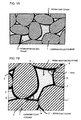
- a matrix is formed by filling voids between the resin coat cover 2-covered carbonaceous powders 1 with the resin reinforcing phase 3.
- a conductive pass is efficiently formed by packing the carbonaceous powder 1 together with other carbonaceous powder 1 or via the resin coat cover 2, and the resulting voids are filled with a binder of highly heat-resistant resin, or the high heat resistance resin reinforcing phase 3 is spread in a face-contacting manner on the surface of the carbonaceous powder 1 under a state in which the periphery of the carbonaceous powder which formed a resin coat cover is surrounded by the resin reinforcing phase, thereby forming a low porosity matrix.
- Upper limit of the porosity of this matrix is generally 10% or less, preferably 8% or less, more preferably 7% or less. When the porosity is larger than this, mechanical strength of the obtained fuel cell separator is apt to reduce. Lower limit of the porosity may be as low as possibly, but when the porosity is approximately up to 2%, particularly up to 1%, the burden required for treatments such as kneading can be reduced and a fuel cell separator having excellent mechanical characteristics and electric characteristics can be prepared. Accordingly, porosity of the matrix is generally from 1 to 10%.
- the resin reinforcing phase 3 is spread in a face-contacting manner on the carbonaceous powder 1 which formed the resin coat cover 2, and that contacting ratio of the periphery of the resin reinforcing phase 3 to the carbonaceous powder 1 which formed the resin coat cover 2 is generally 10% or more, preferably 20% or more.
- a composite material in which the resin reinforcing phase 3 is present between the carbonaceous powders 1 covered with the resin coat cover 2 and a matrix is formed by filling the void part 4 between the carbonaceous powders 1 with the resin reinforcing phase 3, as shown in Fig.
- this contacting ratio to the coat cover can be calculated from the ratio of the total length of the five curves a-b, b-c, d-e, e-f and f-g contacting with the carbonaceous powder 1 which formed the resin coat cover 2 to the total length of the seven curves a-b, b-c, c-d, d-e, e-f, f-g and g-a forming peripheral face of the resin reinforcing phase 3.
- the ratio of the content of the total of the resin coat cover-forming resin to the content of the resin reinforcing phase-forming resin, which constitute the matrix, is generally 1.1 parts by weight or more, preferably 2 parts by weight or more, more preferably 5 parts by weight or more, based on 100 parts by weight of the carbonaceous powder. When the containing ratio is smaller than this, it becomes difficult to obtain mechanical strength of the obtained fuel cell separator. Upper limit of the containing ratio of the total of the resins of the resin coat cover and resin reinforcing phase is generally 150 parts by weight or less, preferably 140 parts by weight or less, more preferably 130 parts by weight or less, based on 100 parts by weight of the carbonaceous powder. When the containing ratio is larger than this, conductivity of the obtained fuel cell separator is apt to reduce.
- lower limit of the ratio (weight ratio) of the content of the resin coat cover-forming resin to the content of the resin reinforcing phase-forming resin is generally 1/99 or more, preferably 9/95 or more.
- upper limit of the ratio (weight ratio) of the content of the resin coat cover-forming resin to the content of the resin reinforcing phase-forming resin is generally 30/70 or less, preferably 25/75, more preferably 20/80 or less.
- Lower limit of bulk density of such a matrix is generally 1.5 g/cc or more, preferably 1.6 g/cc or more, more preferably 1.7 g/cc or more.
- Upper limit of bulk density of the matrix may be as high as possibly, because it is desirable that the carbonaceous powder is packed at high packing ratio, but the density of a pure carbonaceous powder, namely around the density 2.2 g/cc of graphite, is the upper limit. Accordingly, bulk density of the matrix is generally from 1.5 to 2.2 g/cc.
- the composite material of the invention for fuel cell separator molding may have any optional shape but is generally a pellet or a powder form.
- the composite material of the invention for fuel cell separator molding is in a pellet form, it is desirable that it has a size having good treating ability by injection molding, which is generally a diameter of 1 mm ⁇ or more, preferably 1.5 mm ⁇ or more, more preferably 2 mm ⁇ or more, and generally 10 mm ⁇ or less, preferably 7 mm ⁇ or less, more preferably 5 mm ⁇ or less.
- a size which shows good treating ability by compression molding and can effect uniform packing in a die it is desirable that it has a size which shows good treating ability by compression molding and can effect uniform packing in a die, and its average particle size is generally 0.05 mm or more, preferably 0.1 mm or more, more preferably 0.2 mm or more, and generally 1 mm or less, preferably 0.9 mm or less, more preferably 0.8 mm or less, its maximum particle size is generally 2 mm or less, preferably 1.5 mm or less, and its minimum particle size is generally 0.02 mm or more, preferably 0.03 mm or more.
- Such a powder can be prepared by pulverizing the pellet using an optional grinder, or it may be a product of granulation.
- the composite material of the invention for fuel cell separator molding may further contain a conductive material other than the resin coat cover-formed carbonaceous powder.
- a conductive material other than the resin coat cover-formed carbonaceous powder.
- it is desirable that the conductive material is contained in the composite for molding use at a content ratio of 30% by weight or less. Lower limit of the conductive material content ratio is about 0.1% by weight.
- the conductive material to be contained are not particularly limited, its examples include one or two or more species selected from the group consisting of graphite, expanded graphite, carbon black, carbon fiber, vapor phase epitaxy carbon fiber, carbon nanotube, fullerene and metals.
- the metals aluminum, copper, zinc and iron or alloys thereof can be exemplified.
- Shape of the conductive material has no particular limitation, and various shapes such as a scale, a granule, a mass and a fiber can be employed.
- the conductive material is a powdery form, it is desirable that its particle diameter is similar to that of the carbonaceous powder, and it is desirable that a resin coat cover is also formed on this conductive material similar to the case of the carbonaceous powder, because mechanical characteristics of the separator can be further improved.
- a resin coat cover-forming resin (first resin) is completely compatibilyzed in an organic solvent, mixed with a carbonaceous powder to form a resin coat cover and then mixed with a high heat resistance resin (second resin) having low compatibility or substantially having no compatibility with the organic solvent, and the resulting mixture is subjected to heating, melting and kneading to obtain a resin reinforcing phase.
- Compatibility of a resin with an organic solvent has a correlation to the heat resistance of the resin, and there is a tendency that the compatibility with the same organic solvent becomes low as the heat resistance becomes high. That is, when a resin having lower compatibility with the same organic solvent, in comparison with that of a resin which forms a resin coat cover, is used as a resin for forming a resin reinforcing phase, a carbonaceous powder coated with a resin coat cover can form a matrix together with a resin reinforcing phase having higher heat resistance than that of the resin which forms the resin coat cover.
- the resin coat cover-forming resin, resin reinforcing phase-forming resin and carbonaceous powder are as described in the foregoing.
- the organic solvent capable of compatibilyzing with organic solvents means a solvent which shows a resin solubility of 10% or more by the following compatibility test.
- the term "low compatibility" in the case of a resin having low compatibility or substantially having no compatibility with the organic solvent means a resin solubility of 30% or less
- the term “substantially having no compatibility” means a resin solubility of 10% or less.
- an organic solvent having a resin solubility of 10% or less can form a high heat resistance resin reinforcing phase and therefore is desirable.
- the compatibility test is carried out at a ratio identical to the mixing ratio of the used resins and under the same using mode, namely the compatibility test is carried out by mixing resins by a corresponding mode when two or more resins are combined by melting or kneading them, or by a corresponding mode when two or more resins are used by simply mixing them as respective pellet forms.
- the compatibility test is carried out by the same mixing ratio of the used organic solvents and the same using mode.
- the complete compatibility means that a mixture of the organic solvent with the resin for resin coat cover formation use shows a single phase when observed with the naked eye at the time of mixing it with a carbonaceous powder.
- Examples of the organic solvent to be used in the complete compatibilyzation of resins for resin coat cover formation use include alkanes such as butane, pentane, hexane, heptane and octane; cycloalkanes such as cyclopentane, cyclohexane, cycloheptane and cyclooctane; alcohols such as ethanol, propanol, butanol, amyl alcohol, hexanol, heptanol, octanol, decanol, undecanol, diacetone alcohol, furfuryl alcohol and benzyl alcohol; cellosolves such as methyl cellosolve, ethyl cellosolve, butyl cellosolve, methyl cellosolve acetate and ethyl cellosolve acetate; propylene glycols such as propylene glycol monomethyl ether, propylene glycol monoethyl
- Lower limit of the using amount of these organic solvents is generally 0.5 part by weight or more, preferably 1 part by weight or more, more preferably 1.5 parts by weight or more, based on 1 part by weight of the resin for resin coat cover forming use. When the amount is smaller than this, coating with the resin coat cover cannot be carried out sufficiently and it takes much time for recovering the solvent, which are un-efficient.
- Upper limit of the using amount of organic solvents is generally 10 parts by weight or less, preferably 5 parts by weight or less, based on 1 part by weight of the resin for resin coat cover forming use. When the amount is larger than this, the resin cannot be spread sufficiently on the carbonaceous powder surface.
- Mixing of the carbonaceous powder with the organic solvent completely compatibilyzed with the resin for resin coat cover forming use can be carried out by a simple mixing or flushing of the resin for resin coat cover forming use completely compatibilyzed in the organic solvent.
- a method for uniformly mixing them using a mixer such as tumbler blender, ribbon blender, V type blender, Henschel mixer or super mixer, or a method for mixing and kneading them using a kneading machine such as single or twin screw extruder, roll, Banbury mixer, kneader or Brabender, can be employed.
- the carbonaceous powder may be wetted in advance with the used organic solvent.
- Mixing ratio of the carbonaceous powder to the organic solvent completely compatibilyzed with the resin for resin coat cover forming use may be optionally selected such that ratio of the resin for resin coat cover forming use to the carbonaceous powder becomes the range described in the foregoing.
- the temperature condition during this mixing it may be within a range which can effect uniform mixing, or under heating as occasion demands. It is desirable to carry out the mixing generally at room temperature (25°C) or more, preferably at 30°C or more, and 80°C or less, preferably 60°C or less.
- the mixing time is generally from 1 minute to 10 hours, preferably from several minutes to several hours.
- the heating conditions it is desirable to select a temperature and a period by which the organic solvent evaporates.
- the heating temperature is set to 200°C or less
- the heating time is set to a period of from several minutes to scores of hours, and the drying is carried out until the organic solvent content becomes preferably 1% by weight or less.
- the carbonaceous powder which formed the resin coat cover in this manner is mixed with the resin for resin reinforcing phase forming use and heated, or heated and mixed to obtain a mixed melting state and uniformly mixed using a mixer such as tumbler blender, ribbon blender, V type blender, Henschel mixer or super mixer, or mixed, kneaded and extruded using a kneading machine such as single or twin screw extruder, roll, Banbury mixer, kneader or Brabender to obtain pellets which further pulverized as occasion demands.
- a mixer such as tumbler blender, ribbon blender, V type blender, Henschel mixer or super mixer, or mixed, kneaded and extruded using a kneading machine such as single or twin screw extruder, roll, Banbury mixer, kneader or Brabender to obtain pellets which further pulverized as occasion demands.
- the shape of both cases is generally a powdery form, and the lower limit of its average particle size is generally 10 ⁇ m or more.
- the powder rise in the air at the time of mixing or bridge in the hopper to obstruct smooth supply of the powder.
- the upper limit of average particle size quick kneading can be carried out when made into a pellet of generally 5 mm or less, preferably 2 mm, and more preferably when pulverized into 1 mm or less (powdery).
- the organic solvent may be further added as occasion demands.
- the kneading conditions have no particular limitation, and temperature and time may be optionally selected so that kneading can be carried out smoothly, e.g., in the following manner.
- Lower limit of the kneading temperature is generally 50°C or more higher temperature than the melting point of the used resin for resin reinforcing phase, preferably 100°C or more higher temperature. When the temperature is lower than this, quick flow cannot be effected sufficiently and close contact between the resin coat cover and resin reinforcing phase cannot be made sufficiently.
- upper limit of the kneading temperature cannot be defined sweepingly depending on the kinds of resins, too high temperature causes deterioration of the used resins, so that it is set to a level less than the temperature which does not cause the deterioration, that is, generally 450°C or less, preferably 400°C or less.
- the kneading time cannot be defined sweepingly depending on the kneading machine to be used, it is generally from 1 minute to 10 hours, preferably from several minutes to several hours.
- the conductive material is contained in the composite material for molding use by adding it to one or more cases selected from the following (1) to (5).
- the composite material of the invention for fuel cell separator molding is produced preferably by the method of the invention for producing a composite material for fuel cell separator molding, but not limited to this method and it may be produced by another method.
- the fuel cell separator of the invention is produced by heat-melting and molding the composite material of the invention for fuel cell separator molding or a composite material for fuel cell separator molding produced by the method of the invention for producing a composite material for fuel cell separator molding.
- This molding may be any molding method which includes not only compression molding but also injection molding and injection compression molding.
- dimension and shape of the fuel cell separator of the invention are not particularly limited, a flat separator having each of lengthwise and breadthwise lengths of from 50 to 1,000 mm, particularly from 80 to 500 mm, and a thickness of from 0.5 to several 10 mm, particularly from 1 to 10 mm, can be cited.
- channels for reaction gas flow corresponding to the linear protruding rows can be formed on one side or both sides of the molded flat separator.
- Upper limit of the volume resistivity of such a fuel cell separator of the invention is generally 200 m ⁇ cm or less, preferably 150 m ⁇ cm or less, more preferably 100 m ⁇ cm or less.
- the volume resistivity is desirably as low as possible but is generally several m ⁇ cm or more.
- Upper limit of the contact resistance value of the fuel cell separator of the invention is generally 200 m ⁇ cm 2 or less, preferably 150 m ⁇ cm 2 or less, more preferably 100 m ⁇ cm 2 or less.
- the contact resistance value is also desirably as low as possible but is generally several m ⁇ cm2 or more.
- the composite material of the invention for fuel cell separator molding satisfies the following mechanical characteristics (1) and (2).
- a 2,000 g portion of natural graphite powder (average particle size 30 ⁇ m) was mixed with 500 cc of toluene to wet the graphite powder, a solution prepared by dissolving 160 g of polystyrene in 500 cc of toluene was added to the wetted graphite powder, and the mixture was kneaded for 1 hour using a two-arm kneader and then dried by heating at 110°C for 5 hours.
- This kneaded material was put into a high speed mixer together with 64 g of carbon black (Ketchen Black EC (DBP oil absorption 360 cm 3 /100 g, surface area (BET) 800 m 2 /g, volatile matter 0.5%, pH 9.0, ash content 0.05)), 286 g of polyphenylene ether, 667 g of a styrene thermoplastic elastomer which is a hydrogenated derivative of a styrene-butadiene block copolymer (styrene content about 30% by weight) and 500 cc of toluene, and the contents were mixed for 4 minutes and then kneaded using a two screw extruder set at 280°C.
- carbon black Ketchen Black EC (DBP oil absorption 360 cm 3 /100 g, surface area (BET) 800 m 2 /g, volatile matter 0.5%, pH 9.0, ash content 0.05
- polyphenylene ether 667 g of
- the kneaded sample was crudely pulverized to a maximum particle size of 1 mm or less using a mixer to obtain a composite material for fuel separator molding.
- a 100 g portion of the composite material was weighed and packed in a press die for 100 x 100 mm sheet use. This was press-molded for 5 minutes at a temperature of 270°C and under a pressure of 98 MPa, spontaneously cooled to 40°C and then depressurized, thereby producing a separator for a flat fuel cell use having a length, in both length wise and breadthwise, of 100 mm and a thickness of 5 mm.
- the thus obtained composite material for fuel separator molding had a matrix porosity of about 1%, a resin coat cover thickness of about 7 ⁇ m, and a contacting ratio of the resin reinforcing phase periphery to the carbonaceous powder coated with the resin coat cover was about 80%.
- volume resistivity of a flat test piece having a length, in both length wise and breadthwise, of 100 mm and a thickness of 5 mm was measured using a four-terminal system resistance tester ("Loresta MP" mfd. by Mitsubishi Kagaku). The volume resistivity was 293 m ⁇ cm as an average value of five points.
- a test piece having a length of 100 mm, a breadth of 10 mm and a thickness of 5 mm was cut out from the separator, and bending strength and distortion by bending rupture of the test piece were measured by applying a load of an indentator to the separator face at a supporting point distance of 80 mm and a test speed of 5 mm/min.
- the bending strength was 30 MPa and the distortion by bending rupture was 1.2 mm (3.0%).
- a 550 g portion of a PAN carbon fiber (mfd. by Mitsubishi Rayon; fiber diameter 7.5 ⁇ m, fiber length 1 cm) was used as the carbonaceous powder and mixed with 250 cc of toluene to wet the carbon fiber, a mixture consisting of 3.8 g of the same carbon black of Example 1, 7.7 g of a vapor phase epitaxy carbon fiber (both conductive materials) and a solution prepared by dissolving 38.5 g of polystyrene in 250 cc of toluene was added to the wetted carbon fiber, and the mixture was kneaded at 40°C for 1 hour using a two-arm kneader and then dried by heating at 100°C for 3 hours.
- This kneaded material was mixed with 30.8 g of carbon black, 61.5 g of vapor phase epitaxy carbon fiber and 307.7 g of polyphenylene sulfide, and the mixture was melt-kneaded using a two screw extruder set at 300°C. Subsequently, the kneaded sample was crudely pulverized to a maximum particle size of 6 mm or less using a cutting mill to obtain a composite material for fuel separator molding.
- This composite material was molded for an injection period of 0.82 second using an injection molding machine set at a die temperature of 100°C and a cylinder temperature of 350°C, thereby producing a separator for a flat fuel cell use having a length, in both length wise and breadthwise, of 100 mm and a thickness of 2 mm.
- the thus obtained composite material for fuel separator molding had a matrix porosity of about 3%, a resin coat cover thickness of about 5 ⁇ m, and a contacting ratio of the resin reinforcing phase periphery to the carbonaceous powder coated with the resin coat cover was about 50%.
- the average fiber length of said carbonaceous fiber in the composite material for fuel cell separator molding was 254 ⁇ m.
- the surface condition when measured with the naked eye was smooth without particular irregularity, and its bulk density was 1.65 g/cc.
- the volume resistivity was measured in the same manner as in Example 1 except that the thickness was changed to 2 mm, its 5 point average value was 22 m ⁇ cm.
- Example 2 the bending strength and distortion by bending rupture were measured in the same manner as in Example 1, except that size of the test piece was changed to a length of 40 mm, a breadth of 40 mm and a thickness of 2 mm, and the supporting point distance was changed to 34 mm.
- the bending strength was 83 MPa and the distortion by bending rupture was 0.29 mm (1.71%).
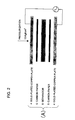
- the contact resistance value was 151 m ⁇ cm 2 . Measuring method of the contact resistance value is described in the following. Firstly, as shown in Fig. 2, both sides of a flat separator plate having a length, in both length wise and breadthwise, of 100 mm and a thickness of 2 mm were covered with sheets of carbon paper having a size of 100 x 100 mm and further covered with gold-plated copper plates of 140 x 140 mm in size. This is to be called test piece (A). As shown in Fig.
- the test piece (A) was put on the center of a pressurization disk (moving side) of a contact resistance tester, and the pressurization disk (moving side) was lifted along the guide by operating a hydraulic jack to carry out compression until entire face of the test piece (A) contacted with the pressurization disk (fixing side) and a bearing of 10 Kgf/cm 2 was applied thereto.
- an insulation treatment is applied to the surface of the pressurization disk.
- Measuring termini of the resistor were connected respectively to the gold-plated copper plates upside and down side of the test Piece (A), and the value of resistance was measured using "HIOKI 3560 AC Milliohm High Tester" manufactured by Hioki Denki. The value of resistance per 1 cm 2 was calculated, and using this value as a contact resistance value (m ⁇ cm 2 ), an average value of five points was used as the measured value.
- a 550 g portion of a PAN carbon fiber was used as the carbonaceous powder and mixed with 346.2 g of polyphenylene sulfide and 34.6 g of carbon black and 69.2 g of a vapor phase epitaxy carbon fiber both as conductive materials, and the mixture was then melt-kneaded using a two screw extruder set at 300°C. Subsequently, the kneaded sample was crudely pulverized to a maximum particle size of 6 mm or less using a cutting mill to obtain a composite material for fuel separator molding.
- This composite material was molded for an injection period of 0.85 second using an injection molding machine set at a die temperature of 100°C and a cylinder temperature of 350°C, thereby producing a separator for a flat fuel cell use having a length, in both length wise and breadthwise, of 100 mm and a thickness of 2 mm.
- the thus obtained composite material for fuel separator molding had a matrix porosity of about 1%, and a contacting ratio of the resin reinforcing phase periphery to the carbonaceous powder was about 5%. Also, average fiber length of carbon fibers in the composite material for fuel separator molding was 167 ⁇ m.
- the surface condition when measured with the naked eye was smooth without particular irregularity, and its bulk density was 1.73 g/cc.
- its volume resistivity was measured in the same manner as in Example 2, its 5 point average value was 24 m ⁇ cm.
- Example 2 the bending strength and distortion by bending rupture were measured in the same manner as in Example 1, except that size of the test piece was changed to a length of 40 mm, a breadth of 40 mm and a thickness of 2 mm, and the supporting point distance was changed to 34 mm.
- the bending strength was 70 MPa and the distortion by bending rupture was 0.18 mm (1.06%).
- a composite material for fuel separator molding was obtained in the same manner as in Example 2, except that natural graphite (average particle size 13 ⁇ m) was used as the carbonaceous powder.
- This composite material was molded for an injection period of 0.94 second using an injection molding machine set at a die temperature of 100°C and a cylinder temperature of 350°C, thereby producing a separator for a flat fuel cell use having a length, in both length wise and breadthwise, of 100 mm and a thickness of 2 mm.
- the thus obtained composite material for fuel separator molding had almost no matrix voids and had a resin coat cover thickness of about 30 ⁇ m, and a contacting ratio of the resin reinforcing phase periphery to the carbonaceous powder coated with the resin coat cover was about 60%.
- the surface condition when measured with the naked eye was smooth without particular irregularity, and its bulk density was 1.96 g/cc.
- the volume resistivity was measured in the same manner as in Example 1 except that the thickness was changed to 2 mm, its 5 point average value was 41 m ⁇ cm.
- Example 2 the bending strength and distortion by bending rupture were measured in the same manner as in Example 1, except that size of the test piece was changed to a length of 40 mm, a breadth of 40 mm and a thickness of 2 mm, and the supporting point distance was changed to 34 mm.
- the bending strength was 48 MPa and the distortion by bending rupture was 0.08 mm (0.47%).
- a composite material for fuel separator molding was obtained in the same manner as in Comparative Example 1, except that natural graphite (average particle size 13 ⁇ m) was used as the carbonaceous powder.
- This composite material was molded for an injection period of 0.90 second using an injection molding machine set at a die temperature of 100°C and a cylinder temperature of 350°C, thereby producing a separator for a flat fuel cell use having a length, in both length wise and breadthwise, of 100 mm and a thickness of 2 mm.
- the thus obtained composite material for fuel separator molding had a matrix porosity of about 4%, and a contacting ratio of the resin reinforcing phase periphery to the carbonaceous powder was about 30%.
- the surface condition when measured with the naked eye was smooth without particular irregularity, and its bulk density was 1.90 g/cc.
- the volume resistivity was measured in the same manner as in Example 1 except that the thickness was changed to 2 mm, its 5 point average value was 49 m ⁇ cm.
- Example 2 the bending strength and distortion by bending rupture were measured in the same manner as in Example 1, except that size of the test piece was changed to a length of 40 mm, a breadth of 40 mm and a thickness of 2 mm, and the supporting point distance was changed to 34 mm.
- the bending strength was 46 MPa and the distortion by bending rupture was 0.07 mm (0.41%).
- a 900 g portion of natural graphite powder (average particle size 13 ⁇ m) was mixed with 250 cc of toluene to wet the graphite powder, a solution prepared by dissolving 50 g of polystyrene in 250 cc of toluene was added to the wetted graphite powder, and the mixture was kneaded at 40°C for 1 hour using a two-arm kneader and then dried by heating at 100°C for 3 hours. This kneaded material was mixed with 50 g of polyphenylene sulfide and then kneaded using a two screw extruder set at 300°C.
- the kneaded sample was crudely pulverized to a maximum particle size of 1 mm or less using a mixer to obtain a composite material for fuel separator molding.
- a 100 g portion of the composite material was weighed and packed in a press die for 100 x 100 mm sheet use. This was press-molded for 5 minutes at a temperature of 300°C and under a pressure of 98 MPa, spontaneously cooled to 40°C and then depressurized, thereby producing a separator for a flat fuel cell use having a length, in both length wise and breadthwise, of 100 mm and a thickness of 5 mm.
- the thus obtained composite material for fuel separator molding had a matrix porosity of about 1% and a resin coat cover thickness of about 10 ⁇ m, and a contacting ratio of the resin reinforcing phase periphery to the carbonaceous powder coated with the resin coat cover was about 90%.
- the surface condition when measured with the naked eye was smooth without particular irregularity, and its bulk density was 2.08 g/cc.
- a 900 g portion of natural graphite (average particle size 13 ⁇ m) was mixed with 100 g of polyphenylene sulfide and then kneaded using a two screw extruder set at 300°C. Subsequently, the kneaded sample was crudely pulverized to a maximum particle size of 1 mm or less using a mixer to obtain a composite material for fuel separator molding. A 100 g portion of the composite material was weighed and packed in a press die for 100 x 100 mm sheet use.
- the thus obtained composite material for fuel separator molding had a matrix porosity of about 1%, and a contacting ratio of the resin reinforcing phase periphery to the carbonaceous powder was about 80%.
- the surface condition when measured with the naked eye was smooth without particular irregularity, and its bulk density was 2.09 g/cc.
- Example 4 As shown in Table 2, it is evident from Example 4 and Comparative Example 3 that volume resistivity was reduced and the conductivity of separator was improved by forming a resin coat cover on the carbonaceous powder. In addition, since bending strength and distortion by bending rupture became large, it can be said that mechanical characteristics were also improved.
- Ex. 4 Comp. Ex. 3 Carbonaceous powder (natural graphite) (parts by weight) 90 90 Resin coat cover (part by weight) 5 0 Resin reinforcing phase (parts by weight) 5 10 Porosity (%) ca. 1 ca. 1 Thickness of resin coat cover ( ⁇ m) ca. 10 - Contacting ratio (%) ca. 90 ca. 80 Bulk density (g/cc) 2.08 2.09 Volume resistivity (m ⁇ cm) 8 9 Bending strength (MPa) 67 60 Distortion be bending rupture (%) 1.95 1.60
- a fuel cell separator having both of excellent mechanical characteristics and electric characteristics can be produced.
Landscapes
- Chemical & Material Sciences (AREA)
- Engineering & Computer Science (AREA)
- Manufacturing & Machinery (AREA)
- Ceramic Engineering (AREA)
- Chemical Kinetics & Catalysis (AREA)
- Electrochemistry (AREA)
- Sustainable Energy (AREA)
- Sustainable Development (AREA)
- Life Sciences & Earth Sciences (AREA)
- General Chemical & Material Sciences (AREA)
- Composite Materials (AREA)
- Materials Engineering (AREA)
- Structural Engineering (AREA)
- Organic Chemistry (AREA)
- Inorganic Chemistry (AREA)
- Fuel Cell (AREA)
Abstract
Description
Larger covering ratio of the carbonaceous powder surface with the resin coat cover is desirable, because voids between carbonaceous powders can be efficiently filled with the resin reinforcing phase by increasing conformability between the carbonaceous powder and resin reinforcing phase.
| Ex. 2 | Comp. Ex. 1 | Ex. 3 | Comp. Ex. 2 | ||
| Carbonaceous powder (parts by weight) | Carbon fiber | 55 | 55 | - | - |
| Natural graphite | - | - | 55 | 55 | |
| Resin coat cover + conductive material (part by weight) | 5 | 0 | 5 | 0 | |
| Resin reinforcing phase + conductive material (parts by weight) | 40 | 45 | 40 | 45 | |
| Porosity (%) | ca. 3 | ca. 1 | ca.0 | ca. 4 | |
| Thickness of resin coat cover (µm) | ca. 5 | - | ca 30 | - | |
| Contacting ratio (%) | ca. 50 | ca. 5 | ca. 60 | ca. 30 | |
| Bulk density (g/cc) | 1.65 | 1.73 | 1.96 | 1.90 | |
| Volume resistivity (mΩ·cm) | 22 | 24 | 41 | 49 | |
| Contact resistance value (mΩ·cm2) | 151 | 180 | 175 | 223 | |
| Bending strength (MPa) | 83 | 70 | 48 | 46 | |
| Distortion by bending rupture (%) | 1.71 | 1.06 | 0.47 | 0.41 |
| Ex. 4 | Comp. Ex. 3 | |
| Carbonaceous powder (natural graphite) (parts by weight) | 90 | 90 |
| Resin coat cover (part by weight) | 5 | 0 |
| Resin reinforcing phase (parts by weight) | 5 | 10 |
| Porosity (%) | ca. 1 | ca. 1 |
| Thickness of resin coat cover (µm) | ca. 10 | - |
| Contacting ratio (%) | ca. 90 | ca. 80 |
| Bulk density (g/cc) | 2.08 | 2.09 |
| Volume resistivity (mΩ·cm) | 8 | 9 |
| Bending strength (MPa) | 67 | 60 |
| Distortion be bending rupture (%) | 1.95 | 1.60 |
Claims (51)
- A composite material for fuel cell separator molding, which comprises a carbonaceous powder dispersed in a matrix, wherein said matrix comprises a resin coat cover for coating said carbonaceous powder and a resin reinforcing phase having higher heat resistance than a resin which forms said resin coat cover.
- The composite material for fuel cell separator molding according to claim 1, wherein the porosity of said matrix is 10% or less.
- The composite material for fuel cell separator molding according to claim 1 or 2, wherein the average particle size of said carbonaceous powder is within the range of from 1 to 100 µm.
- The composite material for fuel cell separator molding according to claim 1 or 2, wherein the average fiber length of said carbonaceous powder is within the range of from 10 to 500 µm.
- The composite material for fuel cell separator molding according to any one of claims 1 to 4, wherein the thickness of said resin coat cover is within the range of from 1 to 50 µm.
- The composite material for fuel cell separator molding according to any one of claims 1 to 5, wherein the contacting ratio of the periphery of said resin reinforcing phase to the carbonaceous powder coated with said resin coat cover is 10% or more.
- The composite material for fuel cell separator molding according to any one of claims 1 to 6, wherein the total content of resins which form said resin coat cover and resin reinforcing phase is within the range of from 1.1 to 150 parts by weight based on 100 parts by weight of the carbonaceous powder.
- The composite material for fuel cell separator molding according to any one of claims 1 to 7, wherein the content of the resin which forms said resin coat cover is within the range of from 0.1 to 50 parts by weight based on 100 parts by weight of the carbonaceous powder.
- The composite material for fuel cell separator molding according to any one of claims 1 to 8, wherein the content of the resin which forms said resin reinforcing phase is within the range of from 1 to 100 parts by weight based on 100 parts by weight of the carbonaceous powder.
- The composite material for fuel cell separator molding according to any one of claims 1 to 9, wherein the ratio (weight ratio) of the content of the resin which forms said resin coat cover to the content of the resin which forms said resin reinforcing phase is within the range of from 1/99 to 30/70.
- The composite material for fuel cell separator molding according to any one of claims 1 to 10, wherein the bulk density of said composite material is 1.5 g/cc or more.
- The composite material for fuel cell separator molding according to any one of claims 1 to 11, wherein the resin which forms said resin coat cover is a thermoplastic resin.
- The composite material for fuel cell separator molding according to any one of claims 1 to 12, wherein glass transition temperature of the resin which forms said resin coat cover is 100°C or less.
- The composite material for fuel cell separator molding according to any one of claims 1 to 13, wherein the resin which forms said resin reinforcing phase is a thermoplastic resin.
- The composite material for fuel cell separator molding according to any one of claims 1 to 14, wherein glass transition temperature of the resin which forms said resin reinforcing phase is 120°C or more.
- The composite material for fuel cell separator molding according to any one of claims 1 to 15, wherein said composite material further comprises a conductive material other than said carbonaceous powder.
- The composite material for fuel cell separator molding according to claim 16, wherein the content of said conductive material is 30% by weight or less based on the total weight of the composite material.
- The composite material for fuel cell separator molding according to claim 16 or 17, wherein said conductive material is one or two or more species selected from the group consisting of graphite, expanded graphite, carbon black, carbon fiber, vapor phase epitaxy carbon fiber, carbon nanotube, fullerene and metals.
- The composite material for fuel cell separator molding according to any one of claims 16 to 18, wherein said conductive material is contained in the resin coat cover and/or resin reinforcing phase.
- The composite material for fuel cell separator molding according to any one of claims 16 to 19, wherein said conductive material is prepared by coating a powdery conductive material with the resin coat cover.
- The composite material for fuel cell separator molding according to any one of claims 1 to 20, wherein said composite material is in a pellet form.
- The composite material for fuel cell separator molding according to any one of claims 1 to 20, wherein said composite material is in a powdery form.
- A separator for fuel cell, which is produced by heating the composite material for fuel cell separator molding described in any one of claims 1 to 22 and then carrying out injection molding of the resulting material.
- A separator for fuel cell, which is produced by heating the composite material for fuel cell separator molding described in any one of claims 1 to 22 and then carrying out compression molding of the resulting material.
- The separator for fuel cell according to claim 23 or 24, wherein the volume resistivity is 200 mΩ·cm or less.
- The separator for fuel cell according to any one of claims 23 to 25, wherein the contact resistance value is 200 mΩ·cm2 or less.
- The separator for-fuel cell according to any one of claims 23 to 26, wherein bending strength of the separator measured in accordance with JIS K7171 is 30 MPa or more.
- The separator for fuel cell according to any one of claims 23 to 27, wherein distortion by bending rupture of the separator measured in accordance with JIS K7171 is 1% or more.
- A method for producing a composite material for fuel cell separator molding, which comprises completely compatibilyzing a first resin in an organic solvent with which said first resin can be compatibilyzed, mixing this with a carbonaceous powder to form a resin coat cover comprising said first resin on the surface of said carbonaceous powder, subsequently mixing with a second resin having low compatibility with the organic solvent or substantially no compatibility and also having higher heat resistance than the first resin and then subjecting the mixture to heating, kneading and extrusion, thereby obtaining a composite material in which the carbonaceous powder coated with the resin coat cover formed a matrix together with a resin reinforcing phase having higher heat resistance than the resin which forms said resin coat cover.
- The method for producing a composite material for fuel cell separator molding according to claim 29, wherein said organic solvent is one or two or more species selected from the group consisting of alkanes, cycloalkanes, alcohols, cellosolves, propylene glycols, ketones, ethers, esters, halogenated hydrocarbons, aromatic hydrocarbons and high polar solvents.
- The method for producing a composite material for fuel cell separator molding according to claim 29 or 30, wherein glass transition temperature of said first resin is 100°C or less.
- The method for producing a composite material for fuel cell separator molding according to any one of claims 29 to 31, wherein solubility of said second resin in the organic solvent is 30% or less.
- The method for producing a composite material for fuel cell separator molding according to any one of claims 29 to 32, wherein average particle size of said carbonaceous powder is within the range of from 1 to 100 µm.
- The method for producing a composite material for fuel cell separator molding according to any one of claims 29 to 33, wherein glass transition temperature of said second resin is 120°C or more.
- The method for producing a composite material for fuel cell separator molding according to any one of claims 29 to 34, wherein said second resin is one or two or more species selected from the group consisting of polyphenylene sulfide, polysulfone, polyether sulfone, polyallylate, polyamide, polycarbonate, polyphenylene ether, polyethylene terephthalate, polybutylene terephthalate, polyether ether ketone, polyallylsulfone, polyimide, polyamidoimide, polyethylene naphthalate, fluorine-base resins and liquid crystal polymers.
- The method for producing a composite material for fuel cell separator molding according to any one of claims 29 to 35, wherein a conductive material other than the carbonaceous powder is contained in the obtained composite material.
- The method for producing a composite material for fuel cell separator molding according to claim 36, wherein said conductive material is contained in the composite material by adding it to one or more cases selected from the following (1) to (5);(1) the carbonaceous powder,(2) the first resin completely compatibilyzed with the organic solvent,(3) at the time of mixing the first resin completely compatibilyzed with the organic solvent with the carbonaceous powder and/or a mixture thereof,(4) the second resin, and(5) at the time of mixing the resin coat cover-formed carbonaceous powder with the second resin and/or a mixture thereof.
- The method for producing a composite material for fuel cell separator molding according to claim 36 or 37, wherein 30% by weight or less of said conductive material is contained in the obtained composite material.
- The method for producing a composite material for fuel cell separator molding according to any one of claims 36 to 38, wherein said conductive material is one or two or more species selected from the group consisting of graphite, expanded graphite, carbon black, carbon fiber, vapor phase epitaxy carbon fiber, carbon nanotube, fullerene and metals.
- The method for producing a composite material for fuel cell separator molding according to any one of claims 36 to 39, wherein said conductive material is prepared by coating a powdery conductive material with the resin coat cover.
- The method for producing a composite material for fuel cell separator molding according to any one of claims 29 to 40, wherein the extrusion is twin screw extrusion.
- The method for producing a composite material for fuel cell separator molding according to any one of claims 29 to 41, wherein the extruded product is in a pellet form.
- The method for producing a composite material for fuel cell separator molding according to any one of claims 29 to 41, wherein the extruded product is made into a powdery form by a pulverization treatment.
- A separator for fuel cell, which is produced by heating a composite material for fuel cell separator molding produced by the production method of a composite material for fuel cell separator molding described in any one of claims 29 to 43, and then carrying out injection molding of the resulting material.
- A separator for fuel cell, which is produced by heating a composite material for fuel cell separator molding produced by the production method of a composite material for fuel cell separator molding described in any one of claims 29 to 43, and then carrying out compression molding of the resulting material.
- A separator for fuel cell, which has a bending strength of 30 MPa or more when measured in accordance with JIS K7171, a distortion by bending rupture of 1% or more when measured in accordance with JIS K7171, and a volume resistivity of 200 mΩ·cm or less.
- A separator for fuel cell, which has a bending strength of 30 MPa or more when measured in accordance with JIS K7171, a distortion by bending rupture of 1% or more when measured in accordance with JIS K7171, a volume resistivity of 200 mΩ·cm or less and a contact resistance value of 200 mΩ·cm2 or less.
- A method for producing a separator for fuel cell, which comprises heating the composite material for fuel cell separator molding described in any one of claims 1 to 22, and then carrying out injection molding of the resulting material.
- A method for producing a separator for fuel cell, which comprises heating the composite material for fuel cell separator molding described in any one of claims 1 to 22, and then carrying out compression molding of the resulting material.
- A method for producing a separator for fuel cell, which comprises heating a composite material for fuel cell separator molding produced by the production method of a composite material for fuel cell separator molding described in any one of claims 29 to 43, and then carrying out injection molding of the resulting material.
- A method for producing a separator for fuel cell, which comprises heating a composite material for fuel cell separator molding produced by the production method of a composite material for fuel cell separator molding described in any one of claims 29 to 43, and then carrying out compression molding of the resulting material.
Applications Claiming Priority (2)
| Application Number | Priority Date | Filing Date | Title |
|---|---|---|---|
| JP2001394448 | 2001-12-26 | ||
| JP2001394448 | 2001-12-26 |
Publications (2)
| Publication Number | Publication Date |
|---|---|
| EP1324411A2 true EP1324411A2 (en) | 2003-07-02 |
| EP1324411A3 EP1324411A3 (en) | 2004-12-22 |
Family
ID=19188872
Family Applications (1)
| Application Number | Title | Priority Date | Filing Date |
|---|---|---|---|
| EP02028789A Withdrawn EP1324411A3 (en) | 2001-12-26 | 2002-12-23 | Composite material for fuel cell separator molding and production method thereof, and fuel cell separator which uses the composite material and production method thereof |
Country Status (3)
| Country | Link |
|---|---|
| US (1) | US20030129471A1 (en) |
| EP (1) | EP1324411A3 (en) |
| CN (1) | CN1428879A (en) |
Cited By (7)
| Publication number | Priority date | Publication date | Assignee | Title |
|---|---|---|---|---|
| WO2005029618A3 (en) * | 2003-09-17 | 2005-10-27 | Tiax Llc | Electrochemical devices and components thereof |
| KR100659855B1 (en) | 2005-04-25 | 2006-12-19 | 삼성에스디아이 주식회사 | Secondary Battery Separator |
| EP1553651A4 (en) * | 2002-08-23 | 2008-01-23 | Honda Motor Co Ltd | Fuel cell separator and its manufacturing method |
| WO2008038835A1 (en) * | 2006-09-29 | 2008-04-03 | Showa Denko K.K. | Separator for fuel cell and production method thereof |
| CN100380720C (en) * | 2003-07-08 | 2008-04-09 | Nok株式会社 | Separator for fuel cell |
| WO2012049616A1 (en) * | 2010-10-14 | 2012-04-19 | Ramot At Tel-Aviv University Ltd. | A direct liquid fuel cell having ammonia borane, hydrazine, derivatives thereof or/and mixtures thereof as fuel |
| CN114759210A (en) * | 2022-06-13 | 2022-07-15 | 湖南耕驰新能源科技有限公司 | Preparation method of bipolar plate |
Families Citing this family (33)
| Publication number | Priority date | Publication date | Assignee | Title |
|---|---|---|---|---|
| US6723299B1 (en) | 2001-05-17 | 2004-04-20 | Zyvex Corporation | System and method for manipulating nanotubes |
| US20040034177A1 (en) | 2002-05-02 | 2004-02-19 | Jian Chen | Polymer and method for using the polymer for solubilizing nanotubes |
| US6905667B1 (en) | 2002-05-02 | 2005-06-14 | Zyvex Corporation | Polymer and method for using the polymer for noncovalently functionalizing nanotubes |
| JP2004079194A (en) * | 2002-08-09 | 2004-03-11 | Nisshinbo Ind Inc | Fuel cell separator manufacturing method and fuel cell separator |
| FR2845453B1 (en) * | 2002-10-07 | 2004-11-26 | Nobel Plastiques | PIPELINE FOR THE TRANSPORT OF HYDROGEN-CONTAINING FLUIDS |
| US7858185B2 (en) * | 2003-09-08 | 2010-12-28 | Nantero, Inc. | High purity nanotube fabrics and films |
| CN100337357C (en) * | 2003-05-08 | 2007-09-12 | 大日本油墨化学工业株式会社 | Manufacturing method of fuel cell separator, and fuel cell |
| US7479516B2 (en) | 2003-05-22 | 2009-01-20 | Zyvex Performance Materials, Llc | Nanocomposites and methods thereto |
| CA2534373A1 (en) * | 2003-08-11 | 2005-02-17 | Nippon Pillar Packing Co., Ltd. | Separator for fuel cell and molding material therefor |
| US7375369B2 (en) | 2003-09-08 | 2008-05-20 | Nantero, Inc. | Spin-coatable liquid for formation of high purity nanotube films |
| US7504051B2 (en) * | 2003-09-08 | 2009-03-17 | Nantero, Inc. | Applicator liquid for use in electronic manufacturing processes |
| US20060280992A1 (en) * | 2003-09-10 | 2006-12-14 | Michinari Miyagawa | Fuel cell separator |
| US20050242471A1 (en) * | 2004-04-30 | 2005-11-03 | Bhatt Sanjiv M | Methods for continuously producing shaped articles |
| US7658869B2 (en) * | 2004-06-03 | 2010-02-09 | Nantero, Inc. | Applicator liquid containing ethyl lactate for preparation of nanotube films |
| US7556746B2 (en) * | 2004-06-03 | 2009-07-07 | Nantero, Inc. | Method of making an applicator liquid for electronics fabrication process |
| KR100597897B1 (en) * | 2004-06-19 | 2006-07-06 | 한국타이어 주식회사 | Fuel Cell Separator Molding Material, Manufacturing Method and Fuel Cell Separator and Fuel Cell Produced therefrom |
| US7296576B2 (en) | 2004-08-18 | 2007-11-20 | Zyvex Performance Materials, Llc | Polymers for enhanced solubility of nanomaterials, compositions and methods therefor |
| US20070111975A1 (en) * | 2004-10-07 | 2007-05-17 | Duramed Pharmaceuticals, Inc. | Methods of Hormonal Treatment Utilizing Ascending-Dose Extended Cycle Regimens |
| EP1825038B1 (en) | 2004-12-16 | 2012-09-12 | Nantero, Inc. | Aqueous carbon nanotube applicator liquids and methods for producing applicator liquids thereof |
| US7479654B2 (en) | 2005-05-09 | 2009-01-20 | Nantero, Inc. | Memory arrays using nanotube articles with reprogrammable resistance |
| US7645399B2 (en) * | 2005-05-31 | 2010-01-12 | Xerox Corporation | Electroconductive composition |
| JP2007173131A (en) * | 2005-12-26 | 2007-07-05 | Hitachi Ltd | Fine particle dispersion and conductive pattern forming apparatus using the same |
| US20070154771A1 (en) * | 2006-01-04 | 2007-07-05 | Jang Bor Z | Highly conductive composites for fuel cell flow field plates and bipolar plates |
| TWI351039B (en) * | 2007-05-08 | 2011-10-21 | Ind Tech Res Inst | High electrical conductive composite material |
| JP2008307893A (en) * | 2007-05-14 | 2008-12-25 | Sumitomo Chemical Co Ltd | Laminated porous film |
| JP2008311221A (en) * | 2007-05-14 | 2008-12-25 | Sumitomo Chemical Co Ltd | Laminated porous film |
| JP5109789B2 (en) * | 2007-05-14 | 2012-12-26 | 住友化学株式会社 | Method for producing porous film |
| US9190648B2 (en) * | 2007-06-01 | 2015-11-17 | Daramic Llc | Lead-acid battery separator having enhanced stiffness |
| CN101419851B (en) * | 2007-10-25 | 2012-05-23 | 财团法人工业技术研究院 | Conductive composite material |
| CN105038231A (en) * | 2015-07-31 | 2015-11-11 | 苏州天健竹业科技有限公司 | Anti-impact composite material for outdoor fitness equipment and preparation method of anti-impact composite material |
| CN113136737B (en) * | 2021-02-23 | 2023-07-28 | 上海嘉资新材料科技有限公司 | Preparation method and equipment of carbon fiber paper blank and ultrathin carbon fiber paper |
| DE102021104564A1 (en) | 2021-02-25 | 2022-08-25 | Eisenhuth Gmbh & Co. Kg | Process for the continuous production of bipolar plates from plastic mixed with electrically conductive particles |
| CN114744230B (en) * | 2022-05-10 | 2023-10-20 | 宁波信远材料科技股份有限公司 | Flexible graphite bipolar plate and preparation method thereof |
Family Cites Families (9)
| Publication number | Priority date | Publication date | Assignee | Title |
|---|---|---|---|---|
| JPS585977A (en) * | 1981-07-01 | 1983-01-13 | Agency Of Ind Science & Technol | Manufacture of bipolar plate for alkali water solution electrolyte type fuel cell |
| JPS63289034A (en) * | 1987-05-21 | 1988-11-25 | Toho Rayon Co Ltd | Thermoplastic resin composition and its production |
| JPH05272063A (en) * | 1992-03-24 | 1993-10-19 | Mitsui Toatsu Chem Inc | Surface modifier for carbon fiber |
| JP4000651B2 (en) * | 1998-01-19 | 2007-10-31 | トヨタ自動車株式会社 | Manufacturing method of fuel cell separator |
| US6489051B1 (en) * | 1998-05-27 | 2002-12-03 | Toray Industries, Inc. | Carbon fiber paper for solid polymer fuel cells |
| JP4028940B2 (en) * | 1998-12-17 | 2008-01-09 | 日清紡績株式会社 | FUEL CELL SEPARATOR, MANUFACTURING METHOD THEREOF, AND SOLID POLYMER TYPE FUEL CELL USING THE FUEL CELL SEPARATOR |
| US6379795B1 (en) * | 1999-01-19 | 2002-04-30 | E. I. Du Pont De Nemours And Company | Injection moldable conductive aromatic thermoplastic liquid crystalline polymeric compositions |
| US6365069B2 (en) * | 1999-03-19 | 2002-04-02 | Quantum Composites Inc. | Process of injection molding highly conductive molding compounds and an apparatus for this process |
| CA2405318C (en) * | 2000-04-17 | 2009-10-20 | Johnson Matthey Public Limited Company | Gas diffusion substrate |
-
2002
- 2002-12-23 EP EP02028789A patent/EP1324411A3/en not_active Withdrawn
- 2002-12-24 US US10/327,111 patent/US20030129471A1/en not_active Abandoned
- 2002-12-26 CN CN02159385A patent/CN1428879A/en active Pending
Cited By (11)
| Publication number | Priority date | Publication date | Assignee | Title |
|---|---|---|---|---|
| EP1553651A4 (en) * | 2002-08-23 | 2008-01-23 | Honda Motor Co Ltd | Fuel cell separator and its manufacturing method |
| CN100380720C (en) * | 2003-07-08 | 2008-04-09 | Nok株式会社 | Separator for fuel cell |
| CN101136481B (en) * | 2003-07-08 | 2010-08-25 | Nok株式会社 | Separator for fuel battery |
| WO2005029618A3 (en) * | 2003-09-17 | 2005-10-27 | Tiax Llc | Electrochemical devices and components thereof |
| KR100659855B1 (en) | 2005-04-25 | 2006-12-19 | 삼성에스디아이 주식회사 | Secondary Battery Separator |
| WO2008038835A1 (en) * | 2006-09-29 | 2008-04-03 | Showa Denko K.K. | Separator for fuel cell and production method thereof |
| US8252483B2 (en) | 2006-09-29 | 2012-08-28 | Showa Denko K.K. | Fuel cell separator having a corrugated electrically conducting flow path |
| WO2012049616A1 (en) * | 2010-10-14 | 2012-04-19 | Ramot At Tel-Aviv University Ltd. | A direct liquid fuel cell having ammonia borane, hydrazine, derivatives thereof or/and mixtures thereof as fuel |
| US9786943B2 (en) | 2010-10-14 | 2017-10-10 | Ramot At Tel-Aviv University Ltd. | Direct liquid fuel cell having ammonia borane, hydrazine, derivatives thereof or/and mixtures thereof as fuel |
| CN114759210A (en) * | 2022-06-13 | 2022-07-15 | 湖南耕驰新能源科技有限公司 | Preparation method of bipolar plate |
| CN114759210B (en) * | 2022-06-13 | 2022-09-02 | 湖南耕驰新能源科技有限公司 | Preparation method of bipolar plate |
Also Published As
| Publication number | Publication date |
|---|---|
| CN1428879A (en) | 2003-07-09 |
| US20030129471A1 (en) | 2003-07-10 |
| EP1324411A3 (en) | 2004-12-22 |
Similar Documents
| Publication | Publication Date | Title |
|---|---|---|
| US20030129471A1 (en) | Composite material for fuel cell separator molding and production method thereof, and fuel cell separator which uses the composite material and production method thereof | |
| EP1692737B1 (en) | Electroconductive resin composition and molded product thereof | |
| US7049021B2 (en) | Conductive composition for solid polymer type fuel cell separator, solid polymer type fuel cell separator, solid polymer type fuel cell and solid polymer type fuel cell system using the separator | |
| JP3850427B2 (en) | Carbon fiber bonded body and composite material using the same | |
| KR100789020B1 (en) | Nanocomposite for Fuel Cell Bipolar Plate | |
| US7214430B2 (en) | Composite material | |
| JP5623036B2 (en) | Molding material for fuel cell separator | |
| EP1394878B1 (en) | Separator for solid state polymer type fuel cell and method for producing the same | |
| US20050112441A1 (en) | Electroconductive curable resin composition, cured product thereof and process for producing the same | |
| WO2010116674A1 (en) | Sheet press molding method and method for manufacturing separator for fuel cell | |
| JP2007122927A (en) | Conductive sheet | |
| KR100834057B1 (en) | Fuel cell separator injection molding material, fuel cell separator and fuel cell manufactured therefrom | |
| US20090305111A1 (en) | Electroconductive structure, manufacturing method therefor, and separator for fuel cell | |
| US7611643B2 (en) | Electrically conducting resin composition for fuel cell separator and fuel cell separator | |
| WO2004059766A1 (en) | Curable composition, cured product thereof, molded product thereof and use as fuel cell separator | |
| WO2005043656A1 (en) | Solid polymeric electrolyte type gas diffusion layer for fuel cell | |
| JP2005187811A (en) | Conductive resin composition and molded body thereof | |
| Hui et al. | Characteristics and preparation of polymer/graphite composite bipolar plate for PEM fuel cells | |
| JP3259051B2 (en) | Fuel cell separator base and fuel cell separator using the base | |
| JP4937529B2 (en) | Conductive resin composition for fuel cell separator and fuel cell separator | |
| JP2003257446A (en) | Fuel cell separator molding composite material, method for producing the same, and fuel cell separator using the composite material | |
| JP2007042326A (en) | Fuel cell separator and method for producing the same | |
| CN1957495B (en) | conductive resin composition for fuel cell separator and fuel cell separator | |
| KR20100070823A (en) | Composition for bipolar plate of fuel cell, manufacturing method thereof, and bipolar plate and fuel cell comprising the same | |
| JP2005100814A (en) | Separator for fuel cell, and fuel cell |
Legal Events
| Date | Code | Title | Description |
|---|---|---|---|
| PUAI | Public reference made under article 153(3) epc to a published international application that has entered the european phase |
Free format text: ORIGINAL CODE: 0009012 |
|
| AK | Designated contracting states |
Designated state(s): AT BE BG CH CY CZ DE DK EE ES FI FR GB GR IE IT LI LU MC NL PT SE SI SK TR |
|
| AX | Request for extension of the european patent |
Extension state: AL LT LV MK RO |
|
| RAP1 | Party data changed (applicant data changed or rights of an application transferred) |
Owner name: MITSUBISHI CHEMICAL CORPORATION |
|
| PUAL | Search report despatched |
Free format text: ORIGINAL CODE: 0009013 |
|
| AK | Designated contracting states |
Kind code of ref document: A3 Designated state(s): AT BE BG CH CY CZ DE DK EE ES FI FR GB GR IE IT LI LU MC NL PT SE SI SK TR |
|
| AX | Request for extension of the european patent |
Extension state: AL LT LV MK RO |
|
| AKX | Designation fees paid | ||
| REG | Reference to a national code |
Ref country code: DE Ref legal event code: 8566 |
|
| STAA | Information on the status of an ep patent application or granted ep patent |
Free format text: STATUS: THE APPLICATION IS DEEMED TO BE WITHDRAWN |
|
| 18D | Application deemed to be withdrawn |
Effective date: 20050701 |