EP1323865B1 - Balance construction - Google Patents
Balance construction Download PDFInfo
- Publication number
- EP1323865B1 EP1323865B1 EP02028634A EP02028634A EP1323865B1 EP 1323865 B1 EP1323865 B1 EP 1323865B1 EP 02028634 A EP02028634 A EP 02028634A EP 02028634 A EP02028634 A EP 02028634A EP 1323865 B1 EP1323865 B1 EP 1323865B1
- Authority
- EP
- European Patent Office
- Prior art keywords
- bearing
- sliding
- construction according
- compensating
- turning
- Prior art date
- Legal status (The legal status is an assumption and is not a legal conclusion. Google has not performed a legal analysis and makes no representation as to the accuracy of the status listed.)
- Expired - Lifetime
Links
Images

Classifications
-
- E—FIXED CONSTRUCTIONS
- E01—CONSTRUCTION OF ROADS, RAILWAYS, OR BRIDGES
- E01D—CONSTRUCTION OF BRIDGES, ELEVATED ROADWAYS OR VIADUCTS; ASSEMBLY OF BRIDGES
- E01D19/00—Structural or constructional details of bridges
- E01D19/04—Bearings; Hinges
-
- E—FIXED CONSTRUCTIONS
- E01—CONSTRUCTION OF ROADS, RAILWAYS, OR BRIDGES
- E01B—PERMANENT WAY; PERMANENT-WAY TOOLS; MACHINES FOR MAKING RAILWAYS OF ALL KINDS
- E01B2/00—General structure of permanent way
- E01B2/003—Arrangement of tracks on bridges or in tunnels
-
- E—FIXED CONSTRUCTIONS
- E01—CONSTRUCTION OF ROADS, RAILWAYS, OR BRIDGES
- E01D—CONSTRUCTION OF BRIDGES, ELEVATED ROADWAYS OR VIADUCTS; ASSEMBLY OF BRIDGES
- E01D19/00—Structural or constructional details of bridges
- E01D19/04—Bearings; Hinges
- E01D19/042—Mechanical bearings
- E01D19/047—Pot bearings
-
- E—FIXED CONSTRUCTIONS
- E01—CONSTRUCTION OF ROADS, RAILWAYS, OR BRIDGES
- E01D—CONSTRUCTION OF BRIDGES, ELEVATED ROADWAYS OR VIADUCTS; ASSEMBLY OF BRIDGES
- E01D19/00—Structural or constructional details of bridges
- E01D19/04—Bearings; Hinges
- E01D19/048—Bearings being adjustable once installed; Bearings used in incremental launching
-
- E—FIXED CONSTRUCTIONS
- E01—CONSTRUCTION OF ROADS, RAILWAYS, OR BRIDGES
- E01B—PERMANENT WAY; PERMANENT-WAY TOOLS; MACHINES FOR MAKING RAILWAYS OF ALL KINDS
- E01B1/00—Ballastway; Other means for supporting the sleepers or the track; Drainage of the ballastway
- E01B1/002—Ballastless track, e.g. concrete slab trackway, or with asphalt layers
Definitions
- the invention relates to a compensating construction according to the preamble of claim 1.
- Such a compensation construction is known from DE-A-198 06 566.
- This solution is characterized by the fact that even with bridges of greater length, the movements of the joints can be absorbed.
- a compensating plate bridges the gap and in particular the critical end tangent angle of the track, which generates considerable and dangerous lifting forces at the rail supports, is reduced by a multiple.
- An elastomeric body under load behaves like a non-compressible fluid in volume change. It is therefore known to produce elastomeric bodies with concave side surfaces, so that the side surfaces are substantially straight under load. With a correspondingly high load, a rather soft bearing with the possibility of horizontal displacement arises.
- DE-A-27 46 490 describes a solution for road bridges, which is intended to compensate for the elongation of bridge segments by horizontally sliding and rotatable elements. A vertical movement and thus the necessary degree of freedom to allow compression during load changes to railway constructions, however, is not possible with the solution described here.
- the invention is based on the object to provide a compensation structure for railway construction according to the preamble of claim 1, which is particularly durable, without overwriting the available space, yet the cost, especially the maintenance costs, should be low ,
- the compensation structure according to the invention is characterized by the realization of a pivot bearing, wherein the pivot bearing is combined with a sliding bearing.
- a plain bearing can be extremely durable when using suitable materials such as UHMW, whereby the combination ensures that the sliding disk is always guided parallel to the sliding plate.
- a pivot bearing is basically able to compensate for inclinations.
- the pivot bearing may be formed, for example, as Cincinnatikippgleitlager.
- Such a bearing has a joint socket and a joint head, which fit together and are well pressure resistant.
- tilting movements of the compensating plate do not disturb the sliding movement due to the immediately adjacent arrangement of pivot bearings and plain bearings, but can be absorbed harmoniously and without delay by the rotary bearing.
- the hood body pivot bearing and plain bearing connects and rotational movements can be intercepted precisely guided both in the rail longitudinal direction and in the rail transverse direction.
- the combined rotary and sliding bearing according to the invention provides a low-wear and precise guidance, so that a biaxial angular adjustment is made possible.
- a pivot axis of the pivot bearing according to the invention preferably extends around a horizontal direction, while the other axis of rotation extends around the other horizontal direction.
- the combination of a pivot bearing with a plain bearing opens up the possibility of height adjustment.
- Another advantage of the inventive combination of the pivot bearing with the plain bearing is the protective effect of the hood body.
- the hood body extends almost semicircular and forms a hood so that it is held captive on the pivot bearing.
- the cover angle is preferably 120 ° to 180 ° and in particular about 160 °.
- the height adjustment of the pivot bearing also makes it possible to keep equal in bearing pressure of all necessary for the support of the balance plate plain bearing.
- the wear of the plain bearings is made uniform, so that the maintenance costs decrease.
- an elastic body is additionally provided below the slide bearing, which projects beyond the pivot bearing horizontally.
- the elastic body is torque-safe and allows it to compensate for the response delay of the pivot bearing so that the entire construction is much more durable.
- the exact configuration of the elastic body can be adapted to the requirements in a wide range.
- an additional vertically horrurchender elastic body may be provided, which also absorbs lateral forces elastic.
- the load introduced into the elastic body is significantly lower, for example by one order of magnitude, than when using pure elastomer bearings.
- the elastic body can also be provided between the compensating plate and the pivot bearing if required, it is in accordance with the invention provided advantageous configuration to integrate the elastic body in the bearing block of the pivot bearing.
- the height required according to the invention is so small that the realization of the compensating construction according to the invention is possible even in the case of scarce on-site dimensioning.
- the height may be 200 mm or even less.
- the ball pressure screw of the NOTEkippgleitlagers is preferably sunk in the bearing body, and the bearing forces are added via adjusting nut of the ball pressure screw, the support nut.
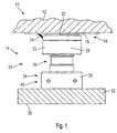
- a compensating structure 10 has in the embodiment shown in FIG. 1 on a balancing plate 12, which is on a plurality of bearings, of which a bearing 14 is shown on a non shown bridge abutment or superstructure end is supported.
- the balance plate 12 is provided on its underside in the areas to be supported with sliding plate 16, which forms part of a sliding bearing 18.
- the sliding bearing 18 also has a sliding disk 20 made of a plastic with low coefficients of friction such as PTFE. It is particularly favorable if the sliding disk 20 consists of ultrahigh molecular weight polyethylene which has a coefficient of friction comparable to PTFE, but is substantially more durable.
- the sliding disk 20 is received on a hood body 22, which supports a sealing lip 24 which extends beyond the sliding disk 20 on the sliding plate 16 is supported.
- the interior thus formed is provided in a manner known per se with lubricant, wherein it is also possible to provide a lubricant supply for the permanent lubrication.
- the hood body 22 is formed to fit a ball pressure screw 26.
- the ball pressure screw 26 and the hood body 22 form condyle and socket of a pivot bearing 28.
- the pivot bearing 28 is height adjustable via an adjustment of the ball pressure screw 26.
- a support nut 30 is provided which projects into a support plate 32 partially and partially supported on the surface of the support plate.
- the support nut 30 has as well as the ball pressure screw 26 has a hexagonal portion 34 and 36, and by adjusting the relative angular position between the ball pressure screw 26 and support nut 30, the height of the pivot bearing 28 is adjustable.
- the angular positions can be adjusted via fixing screws 38 and 40, which are preferably countersunk.
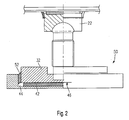
- the bearing 14 according to the invention is provided with an elastic body 42.
- the elastic body 42 extends on the underside of the support plate 40 practically over the entire support plate. In a conventional manner, it consists of elastomeric material and is concave at its edge regions 44 in the unloaded state.
- the underside 46 of the support plate 32 is this formed over the entire surface, while in the embodiment of FIG. 1, a Duchtrittsaus Principleung is provided in extension of the ball pressure screw 26. It is understood that in the embodiment according to FIG. 1, nevertheless, an elastic body can be provided, which then preferably extends annularly or, if necessary, is divided into a plurality of individual elastic bodies.
- the support plate 30 is received together with the elastic body 42 in a bearing body 48.
- the bearing body 48 extends substantially cup-shaped, and the combination of the support plate 32, the elastic body 42 and the bearing body 48 forms a bearing block 50 for the bearing 14th
- a vertical, annular elastic body 52 is additionally provided, which serves for the elastic support of horizontal forces between the support plate 32 and the bearing body 48. Also, the elastic body 52 has in the unloaded state concave side surfaces.
- Fig. 3 From Fig. 3 it can be seen in which way the elastic body 42 and 52 can deform in special load situations.
- the state of both elastic bodies 42 and 52 is shown in the unloaded state.
- the state of the elastic body 42 and 52 is shown in Fig. 3 in the lower region, which is achieved when a load on the bridge by, for example, a train a Slanting the compensating plate initiates.
- a load on the bridge by, for example, a train a Slanting the compensating plate initiates.
- the moments are absorbed both by the elastic body 42 and partially by the elastic body 52, and after response of the pivot bearing 28 takes place in a conventional manner a provision with respect to the recording of moments, but not with respect to the deflection.
- this short-term overshoot makes it possible to reliably prevent the track bearing from being destroyed or at least severely worn by the inclination.
- a particular loading problem with balancing plates for railway bridges is that the load introduction takes place suddenly and then exists as a combined movement, thus requiring both a response of the plain bearing and the rotary bearing. According to the invention exactly this load situation is taken into account by the elastic body.
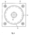
- Fig. 4 is a plan view of the bearing body 48 can be seen.
- the bearing body 48 is fixed with four bolts 54 on the superstructure or the abutment. In a circular recess rests on the elastic body 42 and 52 supported support plate 32nd
- Fig. 4 the recess 56 is further shown, in which the support nut 30 of the ball pressure screw 26 is partially received.
Abstract
Description
Die Erfindung betrifft eine Ausgleichskonstruktion, gemäß dem Oberbegriff von Anspruch 1.The invention relates to a compensating construction according to the preamble of claim 1.
Eine derartige Ausgleichskonstruktion ist aus DE-A-198 06 566 bekannt. Diese Lösung zeichnet sich dadurch aus, dass auch bei Brücken größerer Länge die Fugenbewegungen aufgenommen werden können. Eine Ausgleichsplatte überbrückt die Fuge und insbesondere wird der kritische Endtangentenwinkel der Gleise, der erhebliche und gefährliche Abhebekräfte an den Schienenstützpunkten erzeugt, um ein Vielfaches reduziert.Such a compensation construction is known from DE-A-198 06 566. This solution is characterized by the fact that even with bridges of greater length, the movements of the joints can be absorbed. A compensating plate bridges the gap and in particular the critical end tangent angle of the track, which generates considerable and dangerous lifting forces at the rail supports, is reduced by a multiple.
Diese Lösung ist zwar im Grunde ausgesprochen günstig gegenüber den bislang bekannten Lösungen. Bei der Realisierung der sogenannten festen Fahrbahn, also einer schotterfreien Gleisverlegung, sind hohe Anforderungen an die Lager für die Ausgleichsplatte zu stellen. Andererseits dürfen die Kosten nicht zu stark erhöht werden, um die erwarteten Kostenvorteile der festen Fahrbahn gegenüber einer Schotterkonstrukion nicht ins Gegenteil zu verkehren.Although this solution is basically extremely cheap compared to the previously known solutions. In the realization of the so-called fixed carriageway, so a ballast-free track laying, high demands are placed on the bearings for the balance plate. On the other hand, the costs must not be increased too much in order not to reverse the expected cost advantages of the fixed carriageway compared to a ballast construction.
Aus der genannten Offenlegungsschrift sind für die Lagerung der Ausgleichsplatte auf dem Überbau elastisch oder gleitend verschiebliche Lager bekannt. Derartige Lager können beispielsweise als großvolumige Elastomerblöcke realisiert sein, oder durch eine Kombination aus einer Gleitscheibe und einem Gleitblech, die aufeinander ruhen und die gewünschten Bewegungen ausführen. Im Hinblick auf die zur Verfügung stehende Bauhöhe ist es erforderlich, die Höhe derartiger Lager auf beispielsweise weniger als 200 Millimeter begrenzt zu halten.From the above-mentioned publication elastic or sliding sliding bearings are known for the storage of the balance plate on the superstructure. Such bearings can be realized for example as large-volume elastomer blocks, or by a combination of a sliding disk and a sliding plate, which rest on each other and perform the desired movements. In view of the available height, it is necessary to keep the height of such bearings limited to, for example, less than 200 millimeters.
Ein Elastomerkörper, der unter Last steht, verhält sich hinsichtlich seiner Volumenänderung wie eine nicht-kompressible Flüssigkeit. Es ist bekannt, Elastomerkörper daher mit konkaven Seitenflächen herzustellen, so dass die Seitenflächen unter Belastung im Wesentlichen gerade sind. Bei entsprechend hoher Last entsteht eine recht weiche Lagerung mit der Möglichkeit der Horizontalverschiebung.An elastomeric body under load behaves like a non-compressible fluid in volume change. It is therefore known to produce elastomeric bodies with concave side surfaces, so that the side surfaces are substantially straight under load. With a correspondingly high load, a rather soft bearing with the possibility of horizontal displacement arises.
Andererseits sind derartige Elastomerlager hinsichtlich der Dauerhaltbarkeit eingeschränkt. Die Materialbelastung und Verformung ist nicht unbeachtlich. Zudem entsteht gerade beim Betrieb einer derartigen Ausgleichsplatte im bahnhofsnahen Bereich mit häufigem Lastwechsel eine Walkarbeit, die gerade bei hohen Umgebungstemperaturen für das Elastomerlager belastend wirkt und die Dauerhaltbarkeit weiter reduziert, so dass die gewünschte Haltbarkeit von 20 Jahren bei derartigen Lösungen nicht erreichbar ist.On the other hand, such elastomeric bearings are limited in durability. The material load and deformation is not insignificant. In addition, especially when operating such a compensating plate in the area close to the railway station with frequent load changes a flexing work, which acts stressing especially at high ambient temperatures for the elastomer bearing and durability further reduced, so that the desired durability of 20 years is not achievable in such solutions.
Die DE-A-27 46 490 beschreibt eine Lösung für Straßenbrücken, die die Längendehnung von Brückensegmenten durch horizontal gleit- und drehbewegliche Elemente ausgleichen soll. Eine vertikale Bewegung und damit der nötige Freiheitsgrad, um ein Einfedern bei Lastwechseln an Eisenbahnkonstruktionen zu ermöglichen, ist mit der hier beschriebenen Lösung jedoch nicht möglich.DE-A-27 46 490 describes a solution for road bridges, which is intended to compensate for the elongation of bridge segments by horizontally sliding and rotatable elements. A vertical movement and thus the necessary degree of freedom to allow compression during load changes to railway constructions, however, is not possible with the solution described here.
Aus der US-B-6,324,795 ist darüberhinaus eine kombinierte Kalotten- und Elastomerlagerung für erdbebengefährdete Gebäude bekannt, bei der die Last auf viele kleine Lagereinheiten verteilt werden soll. Durch vergleichsweise besonders hohe Elastomerblöcke sollen punktuelle Vertikalverschiebung des Erdbodens so ausgeglichen werden können, dass sie sich nicht auf das Gebäude übertragen und Spannungsrisse verursachen. Durch die Kalottenlagerung sollen darüberhinaus punktuelle Neigungen des Erdbodens ausgeglichen werden.Furthermore, from US-B-6,324,795 a combined dome and elastomer storage for earthquake-prone buildings is known in which the load is to be distributed to many small storage units. By comparatively high elastomer blocks punctual vertical displacement of the soil are to be compensated so that they do not transfer to the building and cause stress cracks. The calotte bearing is also intended to compensate for punctual slopes of the soil.
Um die sehr hohe Last des Gebäudes und die mögliche große Verschiebung des Erdbodens bei einem Erdbeben aufzufangen, ist die Bauhöhe dieser hier beschriebenen Lager jedoch sehr groß und deshalb für den sehr geringen bei Eisenbahnkonstruktionen zur Vefügung stehenden Raum nicht anwendbar. Auch bedingt der sehr große Elastomerblock eine starke Walkarbeit bei Lastwechseln, die für eine sporadische Belastung wie bei einem Erdbeben durchaus tolerierbar ist, bei der Verwendung für Eisenbahnkonstruktionen jedoch die gewünschte oben erwähnte lange Lebensdauer der. Lager keinesfalls erreichen würde.In order to absorb the very high load of the building and the possible large displacement of the ground in an earthquake, the height of these bearings described here, however, is very large and therefore not applicable for the very small space available in railway constructions space. Also requires the very large elastomer block a strong flexing during load changes, which is quite tolerable for a sporadic load as in an earthquake, however, when used for railway constructions, the desired above-mentioned long life of the. Bearing would not reach.
Ferner ist es im anderen Zusammenhang bekannt geworden, Elastomerlager mit eingelagerten horizontalen Platten zu versehen, die die Verformung reduzieren sollen. Zwar ist die Verformungsneigung eines derartigen Elastomerlagers geringer. Andererseits ist ein derartiges Lager gegenüber Scherkräften und anderen Kräften steifer, so dass die Belastung des Elastomermaterials selbst noch höher wird.Furthermore, it has become known in other contexts to provide elastomeric bearings with embedded horizontal plates, which are intended to reduce the deformation. Although the deformation tendency of such an elastomeric bearing is lower. On the other hand, such a bearing is stiffer to shear forces and other forces, so that the load on the elastomeric material itself becomes even higher.
Daher liegt der Erfindung die Aufgabe zu Grunde, eine Ausgleichskonstruktion für den Eisenbahnbau gemäss dem Oberbegriff von Anspruch 1 zu schaffen, die besonders dauerhaltbar ist, ohne den zu Verfügung stehenden Bauraum zu überschreiben, wobei dennoch die Kosten, insbesondere auch die Wartungskosten, gering sein sollen.Therefore, the invention is based on the object to provide a compensation structure for railway construction according to the preamble of claim 1, which is particularly durable, without overwriting the available space, yet the cost, especially the maintenance costs, should be low ,
Diese Aufgabe wird erfindungsgemäß durch Anspruch 1 gelöst. Vorteilhafte Weiterbildung ergeben sich aus den Unteransprüchen.This object is achieved by claim 1. Advantageous development will become apparent from the dependent claims.
Die erfindungsgemäße Ausgleichskonstruktion zeichnet sich durch die Realisierung eines Drehlagers aus, wobei das Drehlager mit einem Gleitlager kombiniert ist. Ein Gleitlager kann bei Verwendung geeigneter Werkstoffe wie UHMW ausgesprochen langlebig sein, wobei durch die Kombination sichergestellt ist, dass die Gleitscheibe stets parallel zum Gleitblech geführt ist.The compensation structure according to the invention is characterized by the realization of a pivot bearing, wherein the pivot bearing is combined with a sliding bearing. A plain bearing can be extremely durable when using suitable materials such as UHMW, whereby the combination ensures that the sliding disk is always guided parallel to the sliding plate.
Ein Drehlager ist grundsätzlich in der Lage, Schrägstellungen zu kompensieren. Das Drehlager kann beispielsweise als Punktkippgleitlager ausgebildet sein. Ein derartiges Lager weist eine Gelenkpfanne und einen Gelenkkopf aus, die zueinander passen und gut druckbelastbar sind.A pivot bearing is basically able to compensate for inclinations. The pivot bearing may be formed, for example, as Punktkippgleitlager. Such a bearing has a joint socket and a joint head, which fit together and are well pressure resistant.
Erfindungsgemäß besonders günstig ist es, dass durch die unmittelbar benachbarte Anordnung von Drehlager und Gleitlager Kippbewegungen der Ausgleichsplatte die Gleitbewegung nicht stören, sondern harmonisch und verzögerungsfrei vom Drehlager aufgenommen werden können. In diesem Zusammenhang ist es besonders günstig, wenn der Haubenkörper Drehlager und Gleitlager verbindet und Drehbewegungen sowohl in Schienenlängsrichtung als auch in Schienenquerrichtung exakt geführt abgefangen werden können. Das erfindungsgemäße kombinierte Dreh- und Gleitlager bietet eine verschleißarme und exakte Führung, so dass eine zweiachsige winkelanpassung ermöglicht ist.It is particularly favorable according to the invention that tilting movements of the compensating plate do not disturb the sliding movement due to the immediately adjacent arrangement of pivot bearings and plain bearings, but can be absorbed harmoniously and without delay by the rotary bearing. In this context, it is particularly advantageous if the hood body pivot bearing and plain bearing connects and rotational movements can be intercepted precisely guided both in the rail longitudinal direction and in the rail transverse direction. The combined rotary and sliding bearing according to the invention provides a low-wear and precise guidance, so that a biaxial angular adjustment is made possible.
Bevorzugt erstreckt sich dementsprechend eine Schwenkachse des erfindungsgemäßen Drehlagers um eine horizontale Richtung, während sich die andere Drehachse um die andere horizontale Richtung erstreckt.Accordingly, a pivot axis of the pivot bearing according to the invention preferably extends around a horizontal direction, while the other axis of rotation extends around the other horizontal direction.
Erfindungsgemäß besonders günstig ist es, dass die Kombination eines Drehlagers mit einem Gleitlager die Möglichkeit der Höhenverstellbarkeit eröffnet. Dies stellt einen signifikanten Vorteil des erfindungsgemäß besonders günstigen Punktkippgleitlagers gegenüber sogenannten Kalottengleitlagern dar. Ein weiterer Vorteil der erfindungsgemäßen Kombination des Drehlagers mit dem Gleitlager liegt in der Schutzwirkung des Haubenkörpers. Der Haubenkörper erstreckt sich nahezu halbkreisförmig und bildet eine Haube, so dass er unverlierbar auf dem Drehlager gehalten ist. Der Überdeckungswinkel beträgt bevorzugt 120° bis 180° und insbesondere etwa 160°.According to the invention, it is particularly favorable that the combination of a pivot bearing with a plain bearing opens up the possibility of height adjustment. This represents a significant advantage Another advantage of the inventive combination of the pivot bearing with the plain bearing is the protective effect of the hood body. The hood body extends almost semicircular and forms a hood so that it is held captive on the pivot bearing. The cover angle is preferably 120 ° to 180 ° and in particular about 160 °.
Die Höhenverstellbarkeit des Drehlagers ermöglicht es auch, in Auflagerdruck sämtlicher für die Abstützung der Ausgleichsplatte erforderlicher Gleitlager gleich zu halten. Damit wird der Verschleiß der Gleitlager vergleichmäßigt, so dass die Wartungskosten sinken.The height adjustment of the pivot bearing also makes it possible to keep equal in bearing pressure of all necessary for the support of the balance plate plain bearing. Thus, the wear of the plain bearings is made uniform, so that the maintenance costs decrease.
In einer bevorzugten Ausgestaltung ist zusätzlich unterhalb des Gleitlagers ein Elastikkörper vorgesehen, der das Drehlager horizontal überragt. Der Elastikkörper ist damit momentensicher und erlaubt es, die Ansprechverzögerung des Drehlagers so kompensieren, dass die gesamte Konstruktion wesentlich langlebiger wird.In a preferred embodiment, an elastic body is additionally provided below the slide bearing, which projects beyond the pivot bearing horizontally. The elastic body is torque-safe and allows it to compensate for the response delay of the pivot bearing so that the entire construction is much more durable.
Es versteht sich, das erfindungsgemäß die genaue Ausgestaltung des Elastikkörpers in weiten Bereichen an die Erfordernisse anpassbar ist. In vorteilhafter Ausgestaltung kann beispielsweise ein zusätzlicher sich vertikal erstrechender Elastikkörper vorgesehen sein, der auch Seitenkräfte elastisch aufnimmt.It is understood that according to the invention the exact configuration of the elastic body can be adapted to the requirements in a wide range. In an advantageous embodiment, for example, an additional vertically ersturchender elastic body may be provided, which also absorbs lateral forces elastic.
Nachdem die Wesentlichen Lagerkräfte aber erfindungsgemäß durch die dauerhaft auslenkbaren Drehlager und gegebenenfalls das Gleitlager aufgenommen werden, ist die in den Elastikkörper eingeleitete Belastung deutlich, beispielsweise um eine Zehnerpotenz, geringer als bei der Verwendung reiner Elastomerlager.However, according to the invention, after the substantial bearing forces are absorbed by the permanently deflectable pivot bearings and possibly the slide bearing, the load introduced into the elastic body is significantly lower, for example by one order of magnitude, than when using pure elastomer bearings.
Während der Elastikkörper bei Bedarf auch zwischen Ausgleichsplatte und Drehlager vorgesehen sein kann, ist es in erfindungsgemäß vorteilhafter Ausgestaltung vorgesehen, den Elastikkörper in dem Lagerstuhl des Drehlagers zu integrieren.While the elastic body can also be provided between the compensating plate and the pivot bearing if required, it is in accordance with the invention provided advantageous configuration to integrate the elastic body in the bearing block of the pivot bearing.
Durch eine Höhenverstellbarkeit des Drehlagers lässt sich eine Einjustierung vor Ort auch bei schwierigen Einbausituationen realisieren.Due to the height adjustability of the pivot bearing, an on-site adjustment can be realized even in difficult installation situations.
Überraschend ist die erfindlungsgemäß erforderliche Bauhöhe so gering, dass die Realisierung der erfindungsgemäßen Ausgleichskonstruktion auch bei knappen bauseitigen Dimensionierungen möglich ist. Beispielsweise kann die Bauhöhe 200 mm oder sogar weniger betragen. Bevorzugt ist hierzu die Kugeldruckschraube des Punktkippgleitlagers in dem Lagerkörper versenkt, und die Lagerkräfte werden über Stellmutter der Kugeldruckschraube, die Stützmutter, aufgenommen.Surprisingly, the height required according to the invention is so small that the realization of the compensating construction according to the invention is possible even in the case of scarce on-site dimensioning. For example, the height may be 200 mm or even less. For this purpose, the ball pressure screw of the Punktkippgleitlagers is preferably sunk in the bearing body, and the bearing forces are added via adjusting nut of the ball pressure screw, the support nut.
Weitere Vorteile, Einzelheiten und Merkmale ergeben sich aus der nachstehenden Beschreibung zweier Ausführungsbeispiele an Hand der Zeichnungen:Further advantages, details and features will become apparent from the following description of two embodiments with reference to the drawings:
Es zeigen:
- Fig. 1
- einen Schnitt durch einen Teil einer erfindungsgemäßen Ausgleichskonstruktion in einer Ausführungsform;
- Fig. 2
- einen Schnitt durch die Ausführungsform gemäß Fig. 1 jedoch in einer anderen Darstellung;
- Fig. 3
- eine Detailvergrößerung aus Fig. 2; und
- Fig. 4
- eine Draufsicht auf den unteren Teil des erfindungsgemäßen Lagers.
- Fig. 1
- a section through a part of a compensation structure according to the invention in one embodiment;
- Fig. 2
- a section through the embodiment of Figure 1 but in another illustration.
- Fig. 3
- an enlarged detail of Fig. 2; and
- Fig. 4
- a plan view of the lower part of the bearing according to the invention.
Eine Ausgleichskonstruktion 10 weist in dem Ausführungsbeispiel gemäß Fig. 1 eine Ausgleichsplatte 12 auf, die über mehrere Lager, von denen ein Lager 14 dargestellt ist, auf einem nicht dargestellten Brücken-Widerlager oder Überbauende abgestützt ist.A compensating
Die Ausgleichsplatte 12 ist an ihrer Unterseite in den Bereichen, die abgestützt werden sollen, mit Gleitblech 16 versehen, das ein Teil eines Gleitlager 18 bildet.The
Das Gleitlager 18 weist ferner eine Gleitscheibe 20 aus einem Kunststoff mit geringen Reibungskoeffizienten wie PTFE auf. Besonders günstig ist es, wenn die Gleitscheibe 20 aus ultrahochmolekularem Polyethylen besteht, das eine mit PTFE vergleichbaren Reibungskoeffizienten aufweist, jedoch wesentlich dauerhafter ist.The sliding
Die Gleitscheibe 20 ist auf einem Haubenkörper 22 aufgenommen, der eine Dichtlippe 24 abstützt, die über die Gleitscheibe 20 hinausgehend sich auf dem Gleitblech 16 abstützt. Der so gebildete Innenraum ist in an sich bekannter Weise mit Gleitmittel versehen, wobei es auch möglich ist, einen Gleitmittelvorrat für die Dauerschmierung bereitzustellen.The sliding
Der Haubenkörper 22 ist passend zu einer Kugeldruckschraube 26 ausgebildet. Die Kugeldruckschraube 26 und der Haubenkörper 22 bilden Gelenkkopf und Gelenkpfanne eines Drehlagers 28. Das Drehlager 28 ist über einen Verstellung der Kugeldruckschraube 26 höheneinstellbar. Hierzu ist eine Stützmutter 30 vorgesehen, die in eine Stützplatte 32 teilweise hineinragt und sich teilweise auf der Oberfläche der Stützplatte abstützt. Die Stützmutter 30 weist ebenso wie die Kugeldruckschraube 26 einen Sechskantbereich 34 und 36 auf, und durch eine Verstellung der relativen Winkelposition zwischen Kugeldruckschraube 26 und Stützmutter 30 ist die Höhe des Drehlagers 28 einstellbar.The
Die Winkelpositionen lassen sich je über Fixierschrauben 38 und 40 einstellen, die bevorzugt versenkt ausgeführt sind.The angular positions can be adjusted via fixing
Aus Fig. 2 ist ersichtlich, in welcher Weise das erfindungsgemäße Lager 14 mit einem Elastikkörpers 42 versehen ist. Der Elastikkörper 42 erstrecht sich an der Unterseite der Stützplatte 40 praktisch über die gesamte Stützplatte hinweg. In an sich bekannter Weise besteht er aus Elastomermaterial und is an seinen Randbereichen 44 in unbelasteten Zustand konkav ausgebildet.From Fig. 2 it can be seen how the bearing 14 according to the invention is provided with an
In dem Ausführungsbeispiel gemäß Fig. 2 ist die Unterseite 46 der Stützplatte 32 hierzu vollflächig ausgebildet, während bei der Ausführungsform gemäß Fig. 1 eine Duchtrittsausnehmung in Verlängerung der Kugeldruckschraube 26 vorgesehen ist. Es versteht sich, dass bei der Ausführungsform gemäß Fig. 1 dennoch ein Elastikkörper vorgesehen sein kann, der sich dann bevorzugt ringförmig erstreckt oder bei Bedarf auf mehrere Einzel-Elastikkörper aufgeteilt ist.In the embodiment shown in FIG. 2, the
Wie auf Fig. 2 ersichtlich ist, ist die Stützplatte 30 zusammen mit dem Elastikkörper 42 in einem Lagerkörper 48 aufgenommen. Der Lagerkörper 48 erstreckt sich im Wesentlichen napfförmig, und die Kombination aus der Stützplatte 32, dem Elastikkörper 42 und dem Lagerkörper 48 bildet einen Lagerstuhl 50 für das Lager 14.As can be seen in FIG. 2, the
Wie aus Fig. 2, aber auch aus Fig. 3, ersichtlich ist, ist zusätzlich ein vertikaler, ringförmiger Elastikkörper 52 vorgesehen, der der elastischen Abstützung von Horizontalkräften zwischen der Stützplatte 32 und dem Lagerkörper 48 dient. Auch der Elastikkörper 52 weist in unbelastetem Zustand konkave Seitenflächen auf.As can be seen from FIG. 2, but also from FIG. 3, a vertical, annular
Aus Fig. 3 ist ersichtlich, in welcher Weise die Elastikkörper 42 und 52 sich bei besonderen Belastungssituationen verformen können. Im Bereich der Fig. 3 oben ist der Zustand beider Elastikkörper 42 und 52 in unbelastetem Zustand dargestellt. Demgegenüber ist in Fig. 3 im unteren Bereich der Zustand der Elastikkörper 42 und 52 dargestellt, der erreicht wird, wenn eine Belastung der Brücke durch beispielsweise einen Zug eine Schrägstellung der Ausgleichsplatte einleitet. Bis die Kombination aus Haubenkörper 22 und Kugeldruckschraube 26 von der Haftreibung in die Gleitreibung übergeht, entstehen neben der Einfederung im Bereich des Lagerstuhls 50 Momente, die der erfindungsgemäße Elastikkörper auffangen kann.From Fig. 3 it can be seen in which way the
Bei der Ausführungsform gemäß Fig. 3 werden die Momente sowohl durch den Elastikkörper 42 als auch partiell durch den Elastikkörper 52 aufgenommen, und nach Ansprechen der Drehlager 28 erfolgt in an sich bekannter Weise eine Rückstellung hinsichtlich der Aufnahme von Momenten, jedoch nicht hinsichtlich der Einfederung. Dieses kurzzeitige Überschwingen erlaubt es andererseits, sicher zu verhindern, dass das Gleislager durch die Schrägstellung zerstört oder mindestens stark abgenützt wird. Ein besonderes Belastungsproblem bei Ausgleichsplatten für Eisenbahnbrücken ist es, dass die Lasteinleitung plötzlich erfolgt und dann als kombinierte Bewegung vorliegt, also sowohl ein Ansprechen des Gleitlagers als auch des Drehlagers verlangt. Erfindungsgemäß wird genau dieser Belastungssituation durch den Elastikkörper Rechnung getragen.In the embodiment of FIG. 3, the moments are absorbed both by the
Aus Fig. 4 ist eine Draufsicht auf den Lagerkörper 48 ersichtlich. Der Lagerkörper 48 ist mit vier Schraubbolzen 54 an dem Überbau oder dem Widerlager befestigt. In einer kreisrunden Ausnehmung ruht die über die Elastikkörper 42 und 52 abgestützte Stützplatte 32.From Fig. 4 is a plan view of the bearing
In Fig. 4 ist ferner die Ausnehmung 56 dargestellt, in welcher die Stützmutter 30 der Kugeldruckschraube 26 teilweise aufgenommen ist.In Fig. 4, the
Claims (11)
- Compensating construction (10) for bridging a joint in the railway construction, with a supportable compensation plate (12) on a bridge abutment or at least one end of the bridge overhang and bearings (14) for this on the bridge overhang or on the overhang, by means of which the compensation plate (12), in particular when bouncing the bridge, is stored, whereby the bearings (14) are flexibly mobile implemented, characterised in that, each bearing (14) comprises a turning bearing (28) and a sliding bearing (18).
- Compensating construction according to one of the preceding claims, characterised in that the sliding bearing (18) is configured between the turning bearing (28) and the compensation plate (12).
- Compensating construction according to one of the preceding claims, characterised in that the turning bearing (28) is designed as a height adjustable bearing.
- Compensating construction according to one of the preceding claims, characterised in that the turning bearing (28) is designed as point tilting sliding bearing.
- Compensating construction according to one of the preceding claims, characterised in that as known in the art, the sliding bearing (18) consists of a sliding disc (20) above the turning bearing (28), which slides on sliding metal sheets (16), where the sliding disc (20) is manufactured preferably from ultra high molecular polyethylene.
- Compensating construction according to claim 5, characterised in that the sliding bearing (18) is chambered and in particular a sealing rim extends beyond the sliding disc (20) to the sliding metal sheet (16) and slides on this.
- Compensating construction according to one of the preceding claims, characterised in that a hood body (22) and a ball pressure screw (26) of the turning bearing (28) form a ball joint, whose bearing surface takes up an angle from 120° to 180°, preferably approximately 160°.
- Compensating construction according to one of the preceding claims, characterised in that an elastic body (42) extends formed essentially flat or layered beneath the turning bearing (28).
- Compensating construction according to one of the preceding claims, characterised in that the turning bearing (28) comprises a ball pressure screw (26), which is stored in a supporting nut (30), by means of which the turning bearing is height adjustable.
- Compensating construction according to one of the preceding claims, characterised in that the elastic body is designed as part of a bearing support (50) of the turning bearing (28) and between a support plate (32) and a bearing body (48) is essentially taken up along its full surface.
- Compensating construction according to one of the preceding claims, characterised in that the turning bearing (28) is supported on the elastic body, which is preferably made of elastomer.
Applications Claiming Priority (4)
| Application Number | Priority Date | Filing Date | Title |
|---|---|---|---|
| DE10163422 | 2001-12-21 | ||
| DE10163422 | 2001-12-21 | ||
| DE10244993 | 2002-09-26 | ||
| DE10244993A DE10244993B4 (en) | 2001-12-21 | 2002-09-26 | compensation structure |
Publications (3)
| Publication Number | Publication Date |
|---|---|
| EP1323865A2 EP1323865A2 (en) | 2003-07-02 |
| EP1323865A3 EP1323865A3 (en) | 2004-01-14 |
| EP1323865B1 true EP1323865B1 (en) | 2006-09-27 |
Family
ID=26010845
Family Applications (1)
| Application Number | Title | Priority Date | Filing Date |
|---|---|---|---|
| EP02028634A Expired - Lifetime EP1323865B1 (en) | 2001-12-21 | 2002-12-20 | Balance construction |
Country Status (3)
| Country | Link |
|---|---|
| EP (1) | EP1323865B1 (en) |
| AT (1) | ATE340896T1 (en) |
| DE (1) | DE50208246D1 (en) |
Families Citing this family (1)
| Publication number | Priority date | Publication date | Assignee | Title |
|---|---|---|---|---|
| CN110055826B (en) * | 2019-04-28 | 2023-09-22 | 中铁二院工程集团有限责任公司 | Construction method of cutting rack rail reinforced track bed structure |
Family Cites Families (5)
| Publication number | Priority date | Publication date | Assignee | Title |
|---|---|---|---|---|
| DE801730C (en) * | 1948-11-27 | 1951-01-22 | Gutehoffnungshuette Oberhausen | Pivot bearing for folding bridges |
| DE2461325B1 (en) * | 1974-12-24 | 1976-04-01 | Kober Ag | Plain bearings for bridges or similar structures |
| DE2746490C3 (en) * | 1977-10-15 | 1982-05-19 | Friedrich Maurer Söhne GmbH & Co KG, 8000 München | Bridging device for expansion joints in bridges or the like. |
| DE19806566C5 (en) | 1998-02-17 | 2007-04-05 | Stog, Arnulf | Balancing plate for railway bridges |
| US6324795B1 (en) * | 1999-11-24 | 2001-12-04 | Ever-Level Foundation Systems, Inc. | Seismic isolation system between floor and foundation comprising a ball and socket joint and elastic or elastomeric element |
-
2002
- 2002-12-20 DE DE50208246T patent/DE50208246D1/en not_active Expired - Lifetime
- 2002-12-20 EP EP02028634A patent/EP1323865B1/en not_active Expired - Lifetime
- 2002-12-20 AT AT02028634T patent/ATE340896T1/en active
Also Published As
| Publication number | Publication date |
|---|---|
| ATE340896T1 (en) | 2006-10-15 |
| EP1323865A2 (en) | 2003-07-02 |
| DE50208246D1 (en) | 2006-11-09 |
| EP1323865A3 (en) | 2004-01-14 |
Similar Documents
| Publication | Publication Date | Title |
|---|---|---|
| EP1709248B1 (en) | Device for displacing a tongue blade in addition to a height-adjustable roller device | |
| EP1803964B1 (en) | Hybrid stiffness module for vibration isolation | |
| WO2007073788A2 (en) | Friction pendulum bearing | |
| EP2978897B1 (en) | Junction structure and railway bridge with such a junction structure | |
| DE60122908T2 (en) | PANEELBEFESTIGUNGSELEMENT | |
| EP1323865B1 (en) | Balance construction | |
| DE4219472A1 (en) | Bearing device for railway rails - consists of two angled elements with variable inclination | |
| DE10244993B4 (en) | compensation structure | |
| AT3270U1 (en) | BEARINGS FOR CONSTRUCTIONS AND BRIDGE BEARINGS | |
| EP0400198A1 (en) | Device for resiliently clamping supporting beams in a roadway bridging construction | |
| EP0856610B1 (en) | Manhole or caisson cover | |
| DE102008062973B3 (en) | Device for supporting of bridge constructions, particularly for guiding or anchor point, has calotte that is provided with round collection unit and central hump at cover surface | |
| EP0338124B1 (en) | Bridge deck joint bridging | |
| EP1395709B1 (en) | Bearing system and bearings | |
| EP0155622A2 (en) | Vertically adjustable bearing for the transferring and raising and/or lowering of heavy loads, particularly of bridges | |
| DE3031173A1 (en) | HYDRAULIC PISTON TRACK BRAKE FOR BRAKING RAILWAYS | |
| EP1836404A2 (en) | Friction pendulum bearing | |
| WO2011047881A1 (en) | Structure bearing | |
| DE102022204542B3 (en) | structural plain bearing | |
| DE102015217510B4 (en) | Plain bearing slewing ring | |
| DE1901771A1 (en) | Pressure pad protection in pivot bearing for - structural works | |
| AT521152B1 (en) | Railroad tie | |
| DE102022123421A1 (en) | Structure for guiding a monorail | |
| DE102008049201A1 (en) | Device for supporting a bridge | |
| DE2936113A1 (en) | Spiral chute for bulk goods - made in plate construction from ductile material in one layer to protect downward movement of coal etc. |
Legal Events
| Date | Code | Title | Description |
|---|---|---|---|
| PUAI | Public reference made under article 153(3) epc to a published international application that has entered the european phase |
Free format text: ORIGINAL CODE: 0009012 |
|
| AK | Designated contracting states |
Designated state(s): AT BE BG CH CY CZ DE DK EE ES FI FR GB GR IE IT LI LU MC NL PT SE SI SK TR |
|
| AX | Request for extension of the european patent |
Extension state: AL LT LV MK RO |
|
| PUAL | Search report despatched |
Free format text: ORIGINAL CODE: 0009013 |
|
| AK | Designated contracting states |
Kind code of ref document: A3 Designated state(s): AT BE BG CH CY CZ DE DK EE ES FI FR GB GR IE IT LI LU MC NL PT SE SI SK TR |
|
| AX | Request for extension of the european patent |
Extension state: AL LT LV MK RO |
|
| 17P | Request for examination filed |
Effective date: 20040710 |
|
| AKX | Designation fees paid |
Designated state(s): AT BE BG CH CY CZ DE DK EE ES FI FR GB GR IE IT LI LU MC NL PT SE SI SK TR |
|
| 17Q | First examination report despatched |
Effective date: 20041209 |
|
| GRAP | Despatch of communication of intention to grant a patent |
Free format text: ORIGINAL CODE: EPIDOSNIGR1 |
|
| GRAS | Grant fee paid |
Free format text: ORIGINAL CODE: EPIDOSNIGR3 |
|
| GRAA | (expected) grant |
Free format text: ORIGINAL CODE: 0009210 |
|
| AK | Designated contracting states |
Kind code of ref document: B1 Designated state(s): AT BE BG CH CY CZ DE DK EE ES FI FR GB GR IE IT LI LU MC NL PT SE SI SK TR |
|
| PG25 | Lapsed in a contracting state [announced via postgrant information from national office to epo] |
Ref country code: IT Free format text: LAPSE BECAUSE OF FAILURE TO SUBMIT A TRANSLATION OF THE DESCRIPTION OR TO PAY THE FEE WITHIN THE PRESCRIBED TIME-LIMIT;WARNING: LAPSES OF ITALIAN PATENTS WITH EFFECTIVE DATE BEFORE 2007 MAY HAVE OCCURRED AT ANY TIME BEFORE 2007. THE CORRECT EFFECTIVE DATE MAY BE DIFFERENT FROM THE ONE RECORDED. Effective date: 20060927 Ref country code: SI Free format text: LAPSE BECAUSE OF FAILURE TO SUBMIT A TRANSLATION OF THE DESCRIPTION OR TO PAY THE FEE WITHIN THE PRESCRIBED TIME-LIMIT Effective date: 20060927 Ref country code: SK Free format text: LAPSE BECAUSE OF FAILURE TO SUBMIT A TRANSLATION OF THE DESCRIPTION OR TO PAY THE FEE WITHIN THE PRESCRIBED TIME-LIMIT Effective date: 20060927 Ref country code: FI Free format text: LAPSE BECAUSE OF FAILURE TO SUBMIT A TRANSLATION OF THE DESCRIPTION OR TO PAY THE FEE WITHIN THE PRESCRIBED TIME-LIMIT Effective date: 20060927 Ref country code: CZ Free format text: LAPSE BECAUSE OF FAILURE TO SUBMIT A TRANSLATION OF THE DESCRIPTION OR TO PAY THE FEE WITHIN THE PRESCRIBED TIME-LIMIT Effective date: 20060927 Ref country code: IE Free format text: LAPSE BECAUSE OF FAILURE TO SUBMIT A TRANSLATION OF THE DESCRIPTION OR TO PAY THE FEE WITHIN THE PRESCRIBED TIME-LIMIT Effective date: 20060927 |
|
| REG | Reference to a national code |
Ref country code: GB Ref legal event code: FG4D Free format text: NOT ENGLISH |
|
| RIN1 | Information on inventor provided before grant (corrected) |
Inventor name: STOG, ARNULF |
|
| REG | Reference to a national code |
Ref country code: CH Ref legal event code: EP Ref country code: CH Ref legal event code: NV Representative=s name: KELLER & PARTNER PATENTANWAELTE AG |
|
| REG | Reference to a national code |
Ref country code: IE Ref legal event code: FG4D Free format text: LANGUAGE OF EP DOCUMENT: GERMAN |
|
| REF | Corresponds to: |
Ref document number: 50208246 Country of ref document: DE Date of ref document: 20061109 Kind code of ref document: P |
|
| PG25 | Lapsed in a contracting state [announced via postgrant information from national office to epo] |
Ref country code: SE Free format text: LAPSE BECAUSE OF FAILURE TO SUBMIT A TRANSLATION OF THE DESCRIPTION OR TO PAY THE FEE WITHIN THE PRESCRIBED TIME-LIMIT Effective date: 20061227 Ref country code: BG Free format text: LAPSE BECAUSE OF FAILURE TO SUBMIT A TRANSLATION OF THE DESCRIPTION OR TO PAY THE FEE WITHIN THE PRESCRIBED TIME-LIMIT Effective date: 20061227 Ref country code: DK Free format text: LAPSE BECAUSE OF FAILURE TO SUBMIT A TRANSLATION OF THE DESCRIPTION OR TO PAY THE FEE WITHIN THE PRESCRIBED TIME-LIMIT Effective date: 20061227 |
|
| PG25 | Lapsed in a contracting state [announced via postgrant information from national office to epo] |
Ref country code: BE Free format text: LAPSE BECAUSE OF NON-PAYMENT OF DUE FEES Effective date: 20061231 Ref country code: MC Free format text: LAPSE BECAUSE OF NON-PAYMENT OF DUE FEES Effective date: 20061231 |
|
| PG25 | Lapsed in a contracting state [announced via postgrant information from national office to epo] |
Ref country code: ES Free format text: LAPSE BECAUSE OF FAILURE TO SUBMIT A TRANSLATION OF THE DESCRIPTION OR TO PAY THE FEE WITHIN THE PRESCRIBED TIME-LIMIT Effective date: 20070107 |
|
| PG25 | Lapsed in a contracting state [announced via postgrant information from national office to epo] |
Ref country code: PT Free format text: LAPSE BECAUSE OF FAILURE TO SUBMIT A TRANSLATION OF THE DESCRIPTION OR TO PAY THE FEE WITHIN THE PRESCRIBED TIME-LIMIT Effective date: 20070313 |
|
| ET | Fr: translation filed | ||
| REG | Reference to a national code |
Ref country code: IE Ref legal event code: FD4D |
|
| GBV | Gb: ep patent (uk) treated as always having been void in accordance with gb section 77(7)/1977 [no translation filed] |
Effective date: 20060927 |
|
| PLBE | No opposition filed within time limit |
Free format text: ORIGINAL CODE: 0009261 |
|
| STAA | Information on the status of an ep patent application or granted ep patent |
Free format text: STATUS: NO OPPOSITION FILED WITHIN TIME LIMIT |
|
| 26N | No opposition filed |
Effective date: 20070628 |
|
| PG25 | Lapsed in a contracting state [announced via postgrant information from national office to epo] |
Ref country code: GB Free format text: LAPSE BECAUSE OF FAILURE TO SUBMIT A TRANSLATION OF THE DESCRIPTION OR TO PAY THE FEE WITHIN THE PRESCRIBED TIME-LIMIT Effective date: 20060927 |
|
| BERE | Be: lapsed |
Owner name: STOG, ARNULF Effective date: 20061231 |
|
| PG25 | Lapsed in a contracting state [announced via postgrant information from national office to epo] |
Ref country code: GR Free format text: LAPSE BECAUSE OF FAILURE TO SUBMIT A TRANSLATION OF THE DESCRIPTION OR TO PAY THE FEE WITHIN THE PRESCRIBED TIME-LIMIT Effective date: 20061228 |
|
| PG25 | Lapsed in a contracting state [announced via postgrant information from national office to epo] |
Ref country code: EE Free format text: LAPSE BECAUSE OF FAILURE TO SUBMIT A TRANSLATION OF THE DESCRIPTION OR TO PAY THE FEE WITHIN THE PRESCRIBED TIME-LIMIT Effective date: 20060927 |
|
| PG25 | Lapsed in a contracting state [announced via postgrant information from national office to epo] |
Ref country code: LU Free format text: LAPSE BECAUSE OF NON-PAYMENT OF DUE FEES Effective date: 20061220 Ref country code: TR Free format text: LAPSE BECAUSE OF FAILURE TO SUBMIT A TRANSLATION OF THE DESCRIPTION OR TO PAY THE FEE WITHIN THE PRESCRIBED TIME-LIMIT Effective date: 20060927 |
|
| PG25 | Lapsed in a contracting state [announced via postgrant information from national office to epo] |
Ref country code: CY Free format text: LAPSE BECAUSE OF FAILURE TO SUBMIT A TRANSLATION OF THE DESCRIPTION OR TO PAY THE FEE WITHIN THE PRESCRIBED TIME-LIMIT Effective date: 20060927 |
|
| PGFP | Annual fee paid to national office [announced via postgrant information from national office to epo] |
Ref country code: NL Payment date: 20141219 Year of fee payment: 13 |
|
| REG | Reference to a national code |
Ref country code: CH Ref legal event code: PCAR Free format text: NEW ADDRESS: EIGERSTRASSE 2 POSTFACH, 3000 BERN 14 (CH) |
|
| PGFP | Annual fee paid to national office [announced via postgrant information from national office to epo] |
Ref country code: FR Payment date: 20141230 Year of fee payment: 13 |
|
| REG | Reference to a national code |
Ref country code: NL Ref legal event code: MM Effective date: 20160101 |
|
| REG | Reference to a national code |
Ref country code: FR Ref legal event code: ST Effective date: 20160831 |
|
| PG25 | Lapsed in a contracting state [announced via postgrant information from national office to epo] |
Ref country code: NL Free format text: LAPSE BECAUSE OF NON-PAYMENT OF DUE FEES Effective date: 20160101 |
|
| PG25 | Lapsed in a contracting state [announced via postgrant information from national office to epo] |
Ref country code: FR Free format text: LAPSE BECAUSE OF NON-PAYMENT OF DUE FEES Effective date: 20151231 |
|
| PGFP | Annual fee paid to national office [announced via postgrant information from national office to epo] |
Ref country code: AT Payment date: 20161228 Year of fee payment: 15 |
|
| PGFP | Annual fee paid to national office [announced via postgrant information from national office to epo] |
Ref country code: CH Payment date: 20170119 Year of fee payment: 15 |
|
| REG | Reference to a national code |
Ref country code: CH Ref legal event code: PL |
|
| REG | Reference to a national code |
Ref country code: AT Ref legal event code: MM01 Ref document number: 340896 Country of ref document: AT Kind code of ref document: T Effective date: 20171220 |
|
| PG25 | Lapsed in a contracting state [announced via postgrant information from national office to epo] |
Ref country code: LI Free format text: LAPSE BECAUSE OF NON-PAYMENT OF DUE FEES Effective date: 20171231 Ref country code: AT Free format text: LAPSE BECAUSE OF NON-PAYMENT OF DUE FEES Effective date: 20171220 Ref country code: CH Free format text: LAPSE BECAUSE OF NON-PAYMENT OF DUE FEES Effective date: 20171231 |
|
| PGFP | Annual fee paid to national office [announced via postgrant information from national office to epo] |
Ref country code: DE Payment date: 20211108 Year of fee payment: 20 |
|
| REG | Reference to a national code |
Ref country code: DE Ref legal event code: R071 Ref document number: 50208246 Country of ref document: DE |