EP1323669A2 - Hydrogen generation apparatus and fuel cell system - Google Patents
Hydrogen generation apparatus and fuel cell system Download PDFInfo
- Publication number
- EP1323669A2 EP1323669A2 EP02028702A EP02028702A EP1323669A2 EP 1323669 A2 EP1323669 A2 EP 1323669A2 EP 02028702 A EP02028702 A EP 02028702A EP 02028702 A EP02028702 A EP 02028702A EP 1323669 A2 EP1323669 A2 EP 1323669A2
- Authority
- EP
- European Patent Office
- Prior art keywords
- water
- section
- hydrogen
- humidifying
- reformed gas
- Prior art date
- Legal status (The legal status is an assumption and is not a legal conclusion. Google has not performed a legal analysis and makes no representation as to the accuracy of the status listed.)
- Withdrawn
Links
Images


Classifications
-
- C—CHEMISTRY; METALLURGY
- C01—INORGANIC CHEMISTRY
- C01B—NON-METALLIC ELEMENTS; COMPOUNDS THEREOF; METALLOIDS OR COMPOUNDS THEREOF NOT COVERED BY SUBCLASS C01C
- C01B3/00—Hydrogen; Gaseous mixtures containing hydrogen; Separation of hydrogen from mixtures containing it; Purification of hydrogen
- C01B3/02—Production of hydrogen or of gaseous mixtures containing a substantial proportion of hydrogen
- C01B3/32—Production of hydrogen or of gaseous mixtures containing a substantial proportion of hydrogen by reaction of gaseous or liquid organic compounds with gasifying agents, e.g. water, carbon dioxide, air
- C01B3/34—Production of hydrogen or of gaseous mixtures containing a substantial proportion of hydrogen by reaction of gaseous or liquid organic compounds with gasifying agents, e.g. water, carbon dioxide, air by reaction of hydrocarbons with gasifying agents
- C01B3/48—Production of hydrogen or of gaseous mixtures containing a substantial proportion of hydrogen by reaction of gaseous or liquid organic compounds with gasifying agents, e.g. water, carbon dioxide, air by reaction of hydrocarbons with gasifying agents followed by reaction of water vapour with carbon monoxide
-
- H—ELECTRICITY
- H01—ELECTRIC ELEMENTS
- H01M—PROCESSES OR MEANS, e.g. BATTERIES, FOR THE DIRECT CONVERSION OF CHEMICAL ENERGY INTO ELECTRICAL ENERGY
- H01M8/00—Fuel cells; Manufacture thereof
- H01M8/06—Combination of fuel cells with means for production of reactants or for treatment of residues
- H01M8/0606—Combination of fuel cells with means for production of reactants or for treatment of residues with means for production of gaseous reactants
- H01M8/0612—Combination of fuel cells with means for production of reactants or for treatment of residues with means for production of gaseous reactants from carbon-containing material
-
- H—ELECTRICITY
- H01—ELECTRIC ELEMENTS
- H01M—PROCESSES OR MEANS, e.g. BATTERIES, FOR THE DIRECT CONVERSION OF CHEMICAL ENERGY INTO ELECTRICAL ENERGY
- H01M8/00—Fuel cells; Manufacture thereof
- H01M8/06—Combination of fuel cells with means for production of reactants or for treatment of residues
- H01M8/0662—Treatment of gaseous reactants or gaseous residues, e.g. cleaning
- H01M8/0668—Removal of carbon monoxide or carbon dioxide
-
- C—CHEMISTRY; METALLURGY
- C01—INORGANIC CHEMISTRY
- C01B—NON-METALLIC ELEMENTS; COMPOUNDS THEREOF; METALLOIDS OR COMPOUNDS THEREOF NOT COVERED BY SUBCLASS C01C
- C01B2203/00—Integrated processes for the production of hydrogen or synthesis gas
- C01B2203/02—Processes for making hydrogen or synthesis gas
- C01B2203/0205—Processes for making hydrogen or synthesis gas containing a reforming step
- C01B2203/0227—Processes for making hydrogen or synthesis gas containing a reforming step containing a catalytic reforming step
- C01B2203/0233—Processes for making hydrogen or synthesis gas containing a reforming step containing a catalytic reforming step the reforming step being a steam reforming step
-
- C—CHEMISTRY; METALLURGY
- C01—INORGANIC CHEMISTRY
- C01B—NON-METALLIC ELEMENTS; COMPOUNDS THEREOF; METALLOIDS OR COMPOUNDS THEREOF NOT COVERED BY SUBCLASS C01C
- C01B2203/00—Integrated processes for the production of hydrogen or synthesis gas
- C01B2203/02—Processes for making hydrogen or synthesis gas
- C01B2203/0283—Processes for making hydrogen or synthesis gas containing a CO-shift step, i.e. a water gas shift step
-
- C—CHEMISTRY; METALLURGY
- C01—INORGANIC CHEMISTRY
- C01B—NON-METALLIC ELEMENTS; COMPOUNDS THEREOF; METALLOIDS OR COMPOUNDS THEREOF NOT COVERED BY SUBCLASS C01C
- C01B2203/00—Integrated processes for the production of hydrogen or synthesis gas
- C01B2203/04—Integrated processes for the production of hydrogen or synthesis gas containing a purification step for the hydrogen or the synthesis gas
- C01B2203/0435—Catalytic purification
- C01B2203/044—Selective oxidation of carbon monoxide
-
- C—CHEMISTRY; METALLURGY
- C01—INORGANIC CHEMISTRY
- C01B—NON-METALLIC ELEMENTS; COMPOUNDS THEREOF; METALLOIDS OR COMPOUNDS THEREOF NOT COVERED BY SUBCLASS C01C
- C01B2203/00—Integrated processes for the production of hydrogen or synthesis gas
- C01B2203/04—Integrated processes for the production of hydrogen or synthesis gas containing a purification step for the hydrogen or the synthesis gas
- C01B2203/0465—Composition of the impurity
- C01B2203/047—Composition of the impurity the impurity being carbon monoxide
-
- C—CHEMISTRY; METALLURGY
- C01—INORGANIC CHEMISTRY
- C01B—NON-METALLIC ELEMENTS; COMPOUNDS THEREOF; METALLOIDS OR COMPOUNDS THEREOF NOT COVERED BY SUBCLASS C01C
- C01B2203/00—Integrated processes for the production of hydrogen or synthesis gas
- C01B2203/06—Integration with other chemical processes
- C01B2203/066—Integration with other chemical processes with fuel cells
-
- C—CHEMISTRY; METALLURGY
- C01—INORGANIC CHEMISTRY
- C01B—NON-METALLIC ELEMENTS; COMPOUNDS THEREOF; METALLOIDS OR COMPOUNDS THEREOF NOT COVERED BY SUBCLASS C01C
- C01B2203/00—Integrated processes for the production of hydrogen or synthesis gas
- C01B2203/12—Feeding the process for making hydrogen or synthesis gas
- C01B2203/1205—Composition of the feed
- C01B2203/1211—Organic compounds or organic mixtures used in the process for making hydrogen or synthesis gas
- C01B2203/1235—Hydrocarbons
- C01B2203/1241—Natural gas or methane
-
- C—CHEMISTRY; METALLURGY
- C01—INORGANIC CHEMISTRY
- C01B—NON-METALLIC ELEMENTS; COMPOUNDS THEREOF; METALLOIDS OR COMPOUNDS THEREOF NOT COVERED BY SUBCLASS C01C
- C01B2203/00—Integrated processes for the production of hydrogen or synthesis gas
- C01B2203/12—Feeding the process for making hydrogen or synthesis gas
- C01B2203/1258—Pre-treatment of the feed
-
- Y—GENERAL TAGGING OF NEW TECHNOLOGICAL DEVELOPMENTS; GENERAL TAGGING OF CROSS-SECTIONAL TECHNOLOGIES SPANNING OVER SEVERAL SECTIONS OF THE IPC; TECHNICAL SUBJECTS COVERED BY FORMER USPC CROSS-REFERENCE ART COLLECTIONS [XRACs] AND DIGESTS
- Y02—TECHNOLOGIES OR APPLICATIONS FOR MITIGATION OR ADAPTATION AGAINST CLIMATE CHANGE
- Y02E—REDUCTION OF GREENHOUSE GAS [GHG] EMISSIONS, RELATED TO ENERGY GENERATION, TRANSMISSION OR DISTRIBUTION
- Y02E60/00—Enabling technologies; Technologies with a potential or indirect contribution to GHG emissions mitigation
- Y02E60/30—Hydrogen technology
- Y02E60/50—Fuel cells
Definitions
- the present invention relates to a hydrogen generation apparatus of generating a reformed gas by reforming a fuel such as a hydrocarbon-based fuel and to a fuel cell system or the like using the hydrogen generation apparatus.
- a fuel-cell power-generating system using a fuel cell has a high power-generation efficiency and moreover, the heat produced with power generation can be effectively used, application of the system to household cogeneration is expected.
- a power-generating system uses not only a fuel cell but also a hydrogen generation apparatus provided with a reformer of generating a reformed gas containing hydrogen by making a hydrocarbon component such as natural gas or LPG, alcohol such as methanol, or a material such as a naphtha component react with water.
- a hydrocarbon component such as natural gas or LPG, alcohol such as methanol, or a material such as a naphtha component react with water.
- a hydrogen generation apparatus has a configuration of using not only a reformer of generating a reformed gas but also a carbon-monoxide-removing section constituted by a shifter of making carbon monoxide shift-react with water and a purifying section of oxidizing carbon monoxide.
- the efficiency of the hydrogen generation apparatus is further deteriorated as the heat quantity to heat the reformer up to a temperature necessary for a reforming reaction increases.
- the hydrogen generation apparatus makes a material such as hydrocarbon react with vaporized water.
- water has an extremely-large amount of evaporative latent heat, the reformer requires much heat in order to vaporized water. Therefore, it is difficult to raise the efficiency of the hydrogen generation apparatus up to a certain value or more.
- the shifter of performing a shift reaction located at the downstream side of the reformer more easily reduces carbon monoxide as the ratio of water vapor to a reformed gas increases at a low temperature and the quantity of air to be supplied necessary for a reaction can be decreased in the purifying section at the downstream side of the shifter. Therefore, excessive consumption of hydrogen can be controlled and stable operations can be performed.
- By increasing the quantity of water vapor and raising a temperature it is possible to further downsize the shifter by decreasing a catalyst volume because the shift reaction rate increases.
- the present invention is achieved to solve the above problems on the conventional hydrogen generation apparatus and its object is to provide a hydrogen generation apparatus operating at a high efficiency while humidifying a material gas with a simple structure and at a low heat quantity and a fuel-cell power-generating system using the hydrogen generation apparatus.
- the 1st invention of the present invention is a hydrogen generation apparatus comprising:
- the 2nd invention of the present invention is the hydrogen generation apparatus according to the 1st invention, wherein said material-humidifying means humidifies said material by at least using the moisture contained in an off-gas discharged from a fuel cell operated by said reformed gas output from said carbon-monoxide-removing means.
- the 3rd invention of the present invention is the hydrogen generation apparatus according to the 1st invention, wherein said material-humidifying means humidifies said material by using the moisture contained in the reformed gas output from said carbon-monoxide-removing means.
- the 4th invention of the present invention is the hydrogen generation apparatus according to the 2nd or the 3rd inventions, wherein said material-humidifying means has a transmission film of transmitting at least moisture and said transmission film is provided so as to form the boundary between the path of said off-gas or said reformed gas and the path of said material.
- the 5th invention of the present invention is the hydrogen generation apparatus according to the 4th invention, wherein said transmission film also transmits hydrogen.
- the 6th invention of the present invention is the hydrogen generation apparatus according to the 2nd invention, wherein said material-humidifying means comprises:
- the 7th invention of the present invention is the hydrogen generation apparatus according to the 4th invention, wherein said material-humidifying means heat-exchanges said off-gas or said reformed gas with said material.
- the 8th invention of the present invention is the hydrogen generation apparatus according to the 6th invention, wherein said off-gas is used to heat said reformer, and said voltage-applying means controls the temperature of said reformer by adjusting a voltage to be applied to said hydrophilic proton conductor.
- the 9th invention of the present invention is a fuel-cell power-generating system comprising:
- the 10th invention of the present invention is a fuel-cell power-generating system comprising:
- the 11th invention of the present invention is the fuel-cell power-generating system according to the 10th invention, wherein the quantity of the water to be supplied to said material is controlled in accordance with the temperature of said hydrothermal carrying body.
- the 12th invention of the present invention is a hydrogen-generating method comprising:
- the 13th invention of the present invention is the hydrogen-generating method according to the 12th invention, wherein said material-humidifying step includes a step of humidifying said material by at least using the moisture contained in an off-gas discharged from a fuel cell to be operated by the reformed gas output through said carbon-monoxide-removing step, and the hydrogen-generating method further comprising a voltage-applying step of applying a voltage to a hydrophilic proton conductor provided to form the boundary between the path of said off-gas and the path of said material by using said hydrophilic proton conductor.
- the 14th invention of the present invention is the hydrogen-generating method according to the 13th invention, wherein the temperature in said reforming step is controlled by using said off-gas to heat in said reforming step and adjusting a voltage to be applied to said hydrophilic proton conductor in said voltage-applying step.
- FIG. 1 is a schematic sectional view showing a configuration of a hydrogen generation apparatus of this embodiment.
- reference numeral 1 denotes a reformer
- 2 denotes a heating section of heating the reformer
- 3 denotes a material-supplying section of supplying a material to the reformer
- 4 denotes a reforming water-supplying section for supplying water to the reformer 1.
- the reformer 1, the material supplying section 3, and the reforming water-supplying section 4 constitute a reformer of the present invention.
- a CO-shifter 5 corresponding to a shifter of the present invention is set at the downstream side of the reformer 1 and an air-supplying section 6 and a CO-purifying section 7 corresponding to a part of carbon-monoxide-removing means of the present invention are set at the downstream side of the CO-shifter 5.
- the CO-shifter 5 and CO-purifying section 7 constitute carbon-monoxide-removing means of the present invention.
- a fuel-cell power-generating section 8 corresponding to a fuel cell of the present invention is set at the downstream side of the CO-purifying section 7.
- Reference numeral 9 denotes a material-humidifying section corresponding to material-humidifying means of the present invention and 10 denotes a cooling-water-circulating section of circulating cooling water through the fuel-cell power-generating section 8.
- the temperature of cooling water serving as a hydrothermal carrying body of the present invention is detected by a cooling-water-temperature detector 11.
- Reference numeral 12 denotes a combustion-gas-supplying section of supplying a combustion gas to the heating section.
- a reformed catalyst obtained by carrying Ru to alumina is set into the reformer 1
- a transforming catalyst made of copper and zinc is set into the CO-shifter 5
- a CO-purifying catalyst obtained by carrying Pt to alumina is set into the CO-purifying section 7.
- These catalysts are catalysts generally used for a hydrogen generation apparatus. Even if using other catalysts having the same functions, advantages of the present invention are not changed. For example, an Ni catalyst is used as a reforming catalyst, a Pt catalyst or Fe-Cr catalyst is used as a CO-transforming catalyst, and a Ru catalyst or the like is used as a CO-purifying catalyst.
- Materials to be supplied to the reformer 1 include natural gas, methanol, and gasoline and reforming types include water-vapor reforming performed by adding water vapor and partial reforming performed by adding air. A case of obtaining a reformed gas by water-vapor-reforming a natural gas will be described below.
- a natural gas that is a material is supplied from the material-supplying section 3 to the reformer 1.
- Water is supplied from the reforming water-supplying section 4 to the reformer 1 and vaporized into water vapor in the reformer 1.
- the water vapor is mixed with a material and brought into contact with a reformed catalyst set into the reformer 1.
- the reformed catalyst is heated so as to have a temperature close to about 700°C and the material is made to react with water vapor and converted into a reformed gas mainly containing hydrogen.
- the composition of the generated reformed gas slightly depends on the temperature of the reformed catalyst, approx. 80% of hydrogen and approx. 10% of carbon dioxide and approx. 10% of carbon monoxide are respectively contained as an average value excluding water vapor.
- the CO concentration of the reformed gas is reduced to approx. 0.5% through a shift reaction in the CO-shifter 5 set at the downstream side of the reformer 1 and then further reduced to 10 ppm or less by making oxygen in the air supplied from the purifying-air-supplying section 6 react with CO.
- the reformed gas excluding CO is supplied to the fuel-cell power-generating section 8. Because heat is generated simultaneously with electricity under power generation, the fuel-cell power-generating section 8 is cooled by the cooling water supplied by the cooling-water-circulating section 8 to keep a constant temperature. The temperature of the fuel-cell power-generating section 8 is controlled by fluctuating the quantity of cooling water so that the temperature to be detected by the cooling-water detector 11 becomes constant.
- the heated cooling water is sent to the material-humidifying section 9 and used to humidify the material supplied from the material-supplying section 3.
- the material-humidifying section 9 operates so that the material sufficiently contacts with water and the material is humidified up to the dew point at a cooling-water temperature.
- the humidified material is supplied to the reformer 1. Because the cooling-water temperature is generally set to 65°C to 90°C at which the fuel-cell power-generating section 8 shows a high property, the S/C (the ratio of water vapor and carbon in material) after passing through the material-humidifying section 9 approximately ranges between 0.5 and 2. Therefore, water is additionally supplied by the reforming water-supplying section 4 so that the S/C ranges between 2.5 to 3.5 at the reformer 1.
- a wide heat-exchange area is necessary. Because this causes the apparatus to be increased in size, it is difficult to improve the efficiency up to a certain level or higher. Particularly, the water to react with a material in accordance with a reforming reaction has a large amount of evaporative latent heat and this prevents the efficiency from being improved.
- a fuel-cell power-generating section is generally operated so that a temperature of 65° to 90°C is kept constant by cooling the heat produced for at the time of power generation with cooling water. The heat is generally used for hot-water supply.
- this embodiment makes it possible to use some of the heat produced in the fuel-cell power-generating section 8 for humidification of a material and take out some of the water vapor necessary for the reformer 1, it is possible to control the heating value used to vaporize the water to be supplied to the hydrogen generation apparatus.
- a temperature of 100°C or higher is necessary.
- This embodiment uses a section having a configuration of circulating a material gas through a tank of storing cooling water as the material-humidifying section 9.
- any means as the material-humidifying means of the present invention as long as the means has a configuration capable of efficiently bringing cooling water into contact with a material gas.
- a hydrothermal carrying body of the present invention is described as cooling water of directly supplying heat and moisture to a material. Instead, however, it is also possible to heat water with a heat medium such as ethylene glycol and humidify a material with the heated water. In this case, the heat medium indirectly supplies heat and moisture to the material.
- the fuel-cell power-generating section 8 is generally constituted by holding polymer electrolytes with flat electrodes coated with the carbon carrying a noble metal, partitioning them with carbon or metallic separators, and laminating them.
- the section 8 is constituted so as to circulate water by forming a cooling-water channel on the above separators, it is also allowed that the cooling section is constituted so as to efficiently remove the heat produced by electrodes of the fuel-cell power-generating section 8.
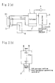
- FIG. 2(a) this embodiment is similar to the embodiment 1 except that a total-heat exchanger 30 corresponding to the material-humidifying means of the present invention is provided at the downstream side of the fuel-cell power-generating section 8. Therefore, this embodiment is described mainly on points different from the embodiment 1 by providing FIG.2(a) with the same symbol for same portions or corresponding portions as that of FIG.1 and omitting detailed descriptions, and thereby an example of a hydrogen generation apparatus of and an example of a hydrogen-generating method of the present invention are described below.
- FIG. 2(a) is a schematic sectional view showing a configuration of a fuel-cell power-generating system of this embodiment.
- a reformed gas generated by a hydrogen generation apparatus is supplied to a fuel-cell power-generating section 8, and most hydrogen is consumed for power generation and discharged as an off-gas. Because the off-gas still contains hydrogen, it is burned together with a heating fuel supplied from a combustion-gas-supplying section 12 by a heating section 2 to heat a reformer 1.
- the off-gas is fully heat-exchanged with a material supplied from the material-supplying section 3 in the total-heat-exchanging section 30.
- a water-transmitting film 30a of separating an off-gas from a material and forming the boundary between the paths of the off-gas and the material is formed in the total-heat-exchanging section 30, the water vapor in the off-gas moves to the material through the water-transmitting film 30a to humidify the material.
- this embodiment uses a water-transmitting film as a transmitting film of the present invention and an electrolytic film used for a polymer fuel cell, any film can be used as long as the film allows water to transmit (such as water-transmitting polymer film) . Even in the case of a film formed by a material such as zeolite capable of transmitting water, the same effect can be obtained.
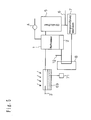
- the embodiment 3 is similar to the embodiment 2 except that a full-heat exchanger 40 corresponding to material-humidifying means of the present invention is set between a CO-purifying section 37 and a fuel-cell power-generating section 38. Therefore, this embodiment will be described mainly on points different from the embodiment 2 by providing FIG.3 with the same symbol for same portions or corresponding portions as that of FIG.2(a) and omitting detailed descriptions.
- the total-heat exchanger 40 has a water-transmitting film of separating a reformed gas discharged from a CO-purifying section 7 from a material and forming the boundary between the path of the reformed gas and that of the material.
- FIG. 3 is a schematic sectional view showing a configuration of a fuel-cell power-generating system of this embodiment.
- the full-heat exchanging section 40 humidifies a material by totally heat-exchanging the reformed gas after passing through the CO-purifying section 7 with a material and moving the water vapor in the reformed gas to the material by a water-transmitting film.
- By humidifying the material it is possible to decrease the quantity of the water to be supplied from a reforming water-supplying section 4 and control the heating value of the reformer 1.
- the reformed gas after passing through the CO-purifying section 7 is usually 100°C or higher which is higher than the operating temperature of the fuel-cell power-generating section 38, it is possible not only to improve the efficiency of the reformer 1 but also to efficiently lower the reformed-gas temperature up to the temperature of the fuel-cell power-generating section 8 and control the water condensation in the pipe between the CO-purifying section 7 and fuel-cell power-generating section 8 by recovering water vapor and heat from the reformed gas between the CO-purifying section 7 and fuel-cell power-generating section 8 at the present embodiment.
- the embodiment 4 is the same as the embodiment 2 except that a total-heat exchanger 50 is set between a CO-shifter 5 and a CO-purifying section 7 and a transformed-water-supplying section 51 for supplying water to the Co-shifter 5 is set at the upstream side of the CO-shifter 5. Therefore, the embodiment 4 is described below mainly on points different from the embodiment 2 by providing FIG.4 same symbol for same portions or corresponding portions as that of FIG.2(a) and omitting detailed descriptions.
- the total-heat exchanger 50 has a water-transmitting film of separating the reformed gas discharged from the CO-shifter 5 from a material and forming the boundary between the path of the reformed gas and the path of the material similarly to the case of the total-heat exchangers 30 and 40.
- FIG. 4 is a schematic sectional view showing a configuration of a fuel-cell power-generating system of this embodiment.
- the water vapor contained in and the heat of the reformed gas are recovered at the downstream side of the CO-purifying section 7.
- troubles occur that the reactivity in the purifying section located at the downstream side of the shifter is deteriorated due to excessive water vapor and the power-generation efficiency may be deteriorated because the quantity of water vapor becomes excessive in the fuel-cell power-generating section located at the downstream side of the purifying section and thereby water is easily condensed on the electrode surface.
- a material and the reformed gas after passing through the CO-shifter 5 are totally heat-exchanged by the full-heat exchanger 50 and the material is humidified by moving the water vapor in the reformed gas to the material through a water-transmitting film.
- water vapor and heat are recovered from the reformed gas after passing through the CO-shifter 45, it is possible to prevent the reactivity of the CO-purifying section 7 from deteriorating due to excessive water vapor or water is condensed on the electrode surface of the fuel-cell power-generating section 8. Thereby it is possible to decrease the volume of the CO-shifter without deteriorating the efficiency of the hydrogen generation apparatus, and stably reduce a CO concentration.
- This embodiment uses the total-heat exchanger 50 as material-humidifying means of the present invention.
- any configuration can be used as long as the configuration makes it possible to recover moisture from the reformed gas output from the CO-shifter 5.
- it is also allowed to use a method of separating a gas from a liquid by cooling a reformed gas with the water to be supplied to the reformer 1 and CO-shifter 5 by the reforming water-supplying section 4 and the transformed-water-supplying section 51 and condensing the moisture in the reformed gas.
- it is allowed to use a configuration excluding the transforming-water-supplying section 51.
- the embodiment 5 is the same as the embodiment 1 except that a material-humidifying section 69 storing the water heated by sunlight therein is set between a material-supplying section 3 and a reformer 1. Therefore, the embodiment 5 is described mainly on points different from the embodiment 1 by providing FIG.5 with the same symbol for the same portions or corresponding portions as that of FIG.1 and omitting detailed descriptions.
- FIG. 5 is a schematic sectional view showing a configuration of a fuel-cell power-generating system of this embodiment.
- the embodiment 1 heats the water in the material-humidifying section 9 by using the heat of the fuel-cell power-generating section 8, a trouble occurs that the efficiency of hot-water supply using the waste heat of the fuel-cell power-generating section 8 is deteriorated.
- the same effect can be obtained by using terrestrial heat instead of sunlight at a spa or the like.
- the embodiment 6 is similar to the embodiment 2 except that a material-humidifying section 80 using a water-hydrogen-transmitting film of transmitting even hydrogen is used instead of the full-heat exchanger 30 having a water-transmitting film 30a. Therefore, this embodiment is described mainly on points different from the embodiment 2 by omitting detailed descriptions.
- FIG. 6 is a schematic sectional view of the material-humidifying section 80 of a fuel-cell power-generating system of this embodiment, in which a water-hydrogen-transmitting film 81 of transmitting moisture and hydrogen is formed at the position where the water-transmitting film 30a is provided.
- a material is humidified by moving the moisture in an off-gas by the water-transmitting film 30a in the total-heat-exchanging section 30 but the whole hydrogen in the off-gas is supplied to the heating section 2.
- this embodiment because some of the hydrogen in an off-gas is returned to a material by transmitting the off-gas from the water-hydrogen-transmitting film 81, it is possible to use the hydrogen not reacting in a fuel-cell power-generating section 8 for fuel-cell power generation again and thereby, the power-generation efficiency is improved.
- a polymer electrolytic film used for a polymer fuel cell is used as the water-hydrogen-transmitting film 81. It is publicly known that a polymer electrolytic film transmits hydrogen. However, in a fuel-cell section, hydrogen transmitted without contributing to power generation reacts with oxygen at the cathode side to deteriorate the power-generation efficiency or damages a film. Therefore, various studies for control are made. In general, hydrogen is easily transmitted when the dew point of a circulating gas is low and a film becomes slightly dry. In the case of this embodiment, hydrogen is easily transmitted because a material gas nearby a material-gas entrance 84 and an off-gas nearby an off-gas exit 83 respectively have a low dew point.
- a water-hydrogen-transmitting film can use not only a polymer electrolytic film but also a zeolite film having a pore diameter capable of transmitting only hydrogen among carbon dioxide and hydrogen, silicon rubber or a film obtained by mixing a hydrophilic compound such as phosphate into a heat-resistant polymer film such as polyimide.
- the driving force of a hydrogen-transmitting film is the difference between hydrogen partial pressures of an off-gas and a material. Therefore, by securing a sufficient area of the film, it is possible to recover hydrogen before the driving force, that is, the difference between hydrogen concentrations of the both sides of a film disappears.
- a designer of a generator can freely select the above mentioned from viewpoints of a cost and a setting space.
- Embodiment 7 of the present invention will be described below.
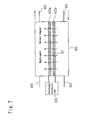
- the embodiment 7 is similar to the embodiment 2 except that a material-humidifying section 90 corresponding to material-humidifying means of the present invention is provided at the downstream side of a fuel-cell power-generating section 8 and the material-humidifying section 90 has the same composition that a carbon electrode 92 carrying platinum is provided on the both faces of it conductive film 91, as the case of a polymer electric fuel cell. Therefore, this embodiment is described mainly on points different from the embodiment 2 and omitting detailed descriptions.
- FIG. 7 is a schematic sectional view of the material-humidifying section 90 of a fuel-cell power-generating system of this embodiment.
- the proton conductive film 91 on which an electrode 92a facing the flow of an off-gas and an electrode 92b facing the flow of a material are arranged is provided at the position where the water-transmitting film 30a is provided.
- the electrodes 92a and 92b are connected to an external voltage controller 93 to generate a potential difference in the material-humidifying section 90 in accordance with a voltage applied from the voltage controller 93.
- the proton conductive film 91 is an example of a hydrophilic proton conductor and the electrodes 92a and 92b and the voltage controller 93 serve as voltage-applying means of the present invention.
- the embodiment 6 humidifies a material by transmitting the moisture and hydrogen in an off-gas depending on the progress by the water-hydrogen-transmitting film 81 in the material-humidifying section 80.
- this embodiment transmits the hydrogen in an off-gas by applying a voltage to the electrodes 92a and 92b set to the both sides of the proton conductive film 91. Therefore, because the quantity of hydrogen to be transmitted can be controlled and hydrogen ions moves followed by water moleculars, it is possible to more efficiently transmit water and hydrogen. In this case, the potential difference between the electrodes 92a and 92b is set so that the potential of the electrode 92b becomes higher than that of the electrode 92a.
- a polymer electric fuel cell having a configuration similar to that of the material-humidifying section 90 is constituted by a hydrogen electrode (reformed-gas electrode) and an oxygen electrode (air electrode), in the case of this embodiment, a material gas is circulated instead of oxygen at the oxygen-electrode side .
- Amaterial gas does not function as an oxidant but it has a function same as an inert gas such as nitrogen. That is, the hydrogen dissociated by a hydrogen electrode becomes ions, and the ions pass through a film and are combined again at the material-gas-side electrode and become hydrogen moleculars. Because the material-humidifying section 90 functions as a concentration cell depending on the difference between hydrogen concentrations of the both electrodes, hydrogen moves by shorting the both electrodes. Moreover, by applying a voltage, it is possible to increase the moving distance of the hydrogen.
- a heating section 2 for heating a reformer 1 is present at the downstream side of an off-gas exit 83, it is possible to control the temperature of the reformer 1 by controlling the transmission rate of hydrogen.
- the transmission rate of hydrogen can be controlled by controlling a voltage to be applied to the electrodes 92a and 92b set to the both faces of the proton conductive film 91 in accordance with the above principle.
- an Ru catalyst of 0.2L is set into a reformer 1
- a copper-zinc catalyst of 2L is set into a CO-shifter 5
- a Pt catalyst of 0.2L is set into a CO-purifying section 7.
- Methane of 7L/min supplied from a material-supplying section 3 is humidified by a material-humidifying section 9 and moreover, water is added by a reforming water-supplying section 4 so that S/C becomes 3 to supply them to the reformer 1.
- the combustion value of a heating section 2 is adjusted so that the Ru catalyst in the reformer 1 becomes 700°C to generate a reformed gas and supply the gas to a fuel-cell power-generating section 8.
- Power is generated by the fuel-cell power-generating section 8 so that DC power becomes 2 kW.
- a power-generation efficiency of 37% is obtained which is calculated in accordance with the total calorific value of the methane supplied to the material-supplying section 3 and heating section 2 and the DC power of 2 kW by adjusting the flow rate of cooling water so that the temperature detected by a cooling-water-temperature-detecting section 11 becomes 80°C.
- a catalyst is set into a reformer 1, CO-shifter 5, and CO-purifying section 7 respectively, similarly to the case of the example 1.
- Methane of 7L/min supplied from a material-supplying section 3 is humidified by a total-heat-exchanging section 30, moreover water is added by a reforming water-supplying section 4 so that S/C becomes 3 to supply them to the reformer 1.
- the combustion value of a heating section 2 is adjusted so that the Ru catalyst in the reformer 1 becomes 700°C to generate a reformed gas and supply the gas to a fuel-cell power-generating section 8.
- Power is generated by the fuel-cell power-generating section 8 so that DC power becomes 2 kW.
- a power-generation efficiency of 38% is obtained which is calculated in accordance with the total calorific value of the methane supplied to the material-supplying section 3 and heating section 2 and the DC power of 2 kW.
- a catalyst is set into a reformer 1, CO-shifter 5, and CO-purifying section 7 respectively, similarly to the case of the example 1.
- Methane of 7L/min supplied from a material-supplying section 3 is humidified by a total-heat-exchanging section 40, moreover water is added by a reforming water-supplying section 4 so that S/C becomes 3 to supply them to the reformer 1.
- the combustion value of a heating section 2 is adjusted so that the Ru catalyst in the reformer 1 becomes 700°C to generate a reformed gas and supply the gas to a fuel-cell power-generating section 8.
- Power is generated by the fuel-cell power-generating section 8 so that DC power becomes 2 kW.
- a power-generation efficiency of 38.5% is obtained which is calculated in accordance with the total calorific value of the methane supplied to the material-supplying section 3 and heating section 2 and the DC power of 2 kW.
- a copper-zinc catalyst of 1L is set into a CO-shifter 5.
- a quantity of a catalyst equal to the case of the example 1 is set into a reformer 1 and CO-purifying section 7 respectively.
- Methane of 7L/min supplied from a material-supplying section 3 is humidified by a total-heat-exchanging section 50 and moreover, water is added by a reforming water-supplying section 54 so that S/C becomes 3 to supply them to the reformer 1.
- the combustion value of a heating section 2 is adjusted so that the Ru catalyst in the reformer 1 becomes 700°C to generate a reformed gas.
- Water is supplied by a shifting-water-supplying section 51 at the upstream side of a CO-shifter 7 so that S/C becomes 5.
- Power is generated by a fuel-cell power-generating section 8 so that DC power becomes 2 kW.
- a power-generation efficiency of 39% is obtained which is calculated in accordance with the total calorific value of the methane supplied to the material-supplying section 3 and heating section 2 and the DC power of 2 kW.
- methane of 7L/min supplied from a material-supplying section 3 is humidified by a material-humidifying section 69 and supplied to a reformer 1 similarly to the case of the example 1.
- a material-humidifying section 9 is painted black so that it is sufficiently exposed to sunlight.
- the water temperature in the material-humidifying section 69 with a humidified-water-temperature-detecting section 71 shows 93°C.
- S/C shows 3.1. Therefore, water is not added to a reforming water-supplying section 4.
- the combustion value of a heating section 2 is adjusted so that the Ru catalyst in the reformer 1 becomes 700°C to generate a reformed gas and supply the gas to a fuel-cell power-generating section 8. Power is generated by the fuel-cell power-generating section 8 so that DC power becomes 2 kW.
- a power generation efficiency of 41% is obtained which is calculated in accordance with the total calorific value of the methane supplied to the material-supplying section 3 and heating section 2 and the DC power of 2 kW.
- a catalyst is set into a reformer 1, CO-shifter 5, and CO-purifying section 7 respectively, similarly to the case of the example 1.
- the material-humidifying section 80 shown in FIG. 6 is set instead of the total-heat-exchanging section 30.
- the methane of 7L/min supplied from a material-supplying section 3 is humidified by the material-humidifying section 80 and moreover, water is added by a reforming water-supplying section 4 so that S/C becomes 3 to supply them to the reformer 1.
- the combustion value of a heating section 2 is adjusted so that the Ru catalyst in the reformer 1 becomes 700°C to generate a reformed gas, supply the gas to a fuel-cell power-generating section 8, and make the section 8 generate power.
- a power-generation efficiency of 41.5% is obtained which is calculated in accordance with the total calorific value of the methane supplied to the material-supplying section 3 and heating section 2 and the generated DC power.
- a catalyst is set into a reformer 1, CO-shifter 5, and CO-purifying section 7 respectively, similarly to the case of the example 1.
- the material-humidifying section 90 shown in FIG. 7 is set instead of the total-heat-exchanging section 30.
- the methane of 7L/min supplied from a material-supplying section 3 is humidified by a material-humidifying section 80 and moreover water is added by a reforming water-supplying section 4 so that S/C becomes 3 to supply them to the reformer 1.
- the combustion value of a heating section 2 is adjusted so that the Ru catalyst in the reformer 1 becomes 700°C to generate a reformed gas, supply the gas to a fuel-cell power-generating section 8, and make the section 8 generate power.
- a voltage of 200 mv is applied to electrodes 92a, 92b at the both faces of a proton conductive film 91.
- a power generation efficiency of 42% is obtained which is calculated in accordance with the total calorific value of the methane supplied to the material-supplying section 3 and heating section 2 and the generated DC power.
- the methane of 7L/min supplied from the material-supplying section 3 is directly supplied to the reformer 1 without humidifying the methane by the material-humidifying section 9.
- power is generated by a fuel-cell power-generating section 8 so that DC power becomes 2 kW.
- the flow rate of cooling water is adjusted so that the temperature detected by a cooling-water-temperature-detecting section 11 becomes 80°C.
- a power generation efficiency of 33% is obtained which is calculated in accordance with the total calorific value of the methane supplied to the material-supplying section 3 and heating section 2 and the DC power of 2 kW.
- Each of the above embodiments is described as a fuel-cell power-generating system including the fuel-cell power-generating section 8. However, it is also allowed to realize the present invention as a single hydrogen generation apparatus excluding the fuel-cell power-generating section 8.
- a fuel-cell power-generating system forms a cycle of supplying the off-gas discharged from the fuel-cell power-generating section 8 to the heating section 2 of the reformer 1.
- a fuel-cell power-generating system of the present invention does not have to form any kind of closed cycles to circulate any gas and materials.
- to humidify a material is the reformed gas directly outputted from reformer 1 or off gas outputted from a fuel-cell power-generation system 8, but the present invention is not limited such a composition. What is meant that material-humidifying means of humidifying material indirectly in the present invention may be to moisture the material by gas other than reformed gas directly outputted from reformer 1 in the fuel-cell power-generation system.
- external means of the present invention is the material-humidifying section 69 to which heat is supplied in the form of sunlight or terrestrial heat.
- external means is not restricted to the section 69. It is allowed to use a system serving as a heat source and moisture-supply source for a material such as a boiler and a refrigerator independent from a fuel-cell power-generating system.
- a heating value necessary for water evaporation can be controlled by a reformer.
Abstract
a reformer of generating a reformed gas containing at least hydrogen and carbon monoxide by making a material containing an organic compound react with water;
carbon-monoxide-removing means of including at least a shifter of reducing the carbon monoxide contained in the reformed gas generated by the reformer in accordance with a shift reaction; and
material-humidifying means of humidifying the material by directly or indirectly using moisture contained in the reformed gas.
Description
- The present invention relates to a hydrogen generation apparatus of generating a reformed gas by reforming a fuel such as a hydrocarbon-based fuel and to a fuel cell system or the like using the hydrogen generation apparatus.
- Because a fuel-cell power-generating system using a fuel cell has a high power-generation efficiency and moreover, the heat produced with power generation can be effectively used, application of the system to household cogeneration is expected.
- In the case of a household purpose, it is preferable to operate a fuel-cell power-generating system at a comparatively low temperature from the viewpoints of correspondence to frequent start/stop of an apparatus, durability of the apparatus, and cost cutting. Therefore, development of a polymer electric fuel cell using a polymer electrolytic film as a power-generating section is progressed.
- Most fuel cells generate power by using hydrogen as a fuel. However, because a reformed-gas infrastructure is not prepared at present, a power-generating system uses not only a fuel cell but also a hydrogen generation apparatus provided with a reformer of generating a reformed gas containing hydrogen by making a hydrocarbon component such as natural gas or LPG, alcohol such as methanol, or a material such as a naphtha component react with water.
- Not only hydrogen but also carbon dioxide and carbon monoxide are contained in the reformed gas generated by the reformer as auxiliary components. Because a polymer electric fuel cell being currently developed operates at a low temperature of 100°C or lower, it is necessary to minimize the carbon monoxide contained in a reformed gas in order to maintain the activity of a cell electrode catalyst. Therefore, a hydrogen generation apparatus has a configuration of using not only a reformer of generating a reformed gas but also a carbon-monoxide-removing section constituted by a shifter of making carbon monoxide shift-react with water and a purifying section of oxidizing carbon monoxide.
- The efficiency of the hydrogen generation apparatus is further deteriorated as the heat quantity to heat the reformer up to a temperature necessary for a reforming reaction increases.
- The hydrogen generation apparatus makes a material such as hydrocarbon react with vaporized water. However, because water has an extremely-large amount of evaporative latent heat, the reformer requires much heat in order to vaporized water. Therefore, it is difficult to raise the efficiency of the hydrogen generation apparatus up to a certain value or more.
- On the other hand, because the shift reaction is an exothermic equilibrium reaction, the shifter of performing a shift reaction located at the downstream side of the reformer more easily reduces carbon monoxide as the ratio of water vapor to a reformed gas increases at a low temperature and the quantity of air to be supplied necessary for a reaction can be decreased in the purifying section at the downstream side of the shifter. Therefore, excessive consumption of hydrogen can be controlled and stable operations can be performed. By increasing the quantity of water vapor and raising a temperature, it is possible to further downsize the shifter by decreasing a catalyst volume because the shift reaction rate increases.
- However, because the water vapor in the shifter is obtained by the reformer and a large amount of evaporative latent heat is necessary in order to increase the quantity of water vapor as described above, the heat quantity required to heat the reformer increases and increasing the quantity of water vapor in the reformer in order to improve the efficiency of the shifter and downsize the section causes the efficiency of the reformer to lower.
- To prevent the above mentioned, a technique is proposed which performs humidification by adding separately-prepared water to a material gas (for example, refer to Japanese Patent Laid-Open No. 10-330101 and Japanese Patent Laid-Open No. 11-106204). Thereby, because evaporative latent heat to change water to water vapor is decreased, it is possible to reduce the heat quantity necessary for a reforming device and improve the efficiency of a shift reaction in the shifter. Moreover, by using the carbon-monoxide-removing section or the heat of the cooling water for a fuel cell, it is possible to perform humidification without lowering the efficiency.
- However, a material gas used for a conventional hydrogen generation apparatus is only humidified by using a heat source in the generator. Thereby, problems occur that improvement of efficiency is limited and piping for heat recovery and humidification becomes complicated.
- The present invention is achieved to solve the above problems on the conventional hydrogen generation apparatus and its object is to provide a hydrogen generation apparatus operating at a high efficiency while humidifying a material gas with a simple structure and at a low heat quantity and a fuel-cell power-generating system using the hydrogen generation apparatus.
- The 1st invention of the present invention is a hydrogen generation apparatus comprising:
- a reformer of generating a reformed gas containing at least hydrogen and carbon monoxide by making a material containing an organic compound react with water;
- carbon-monoxide-removing means of including at least a shifter of reducing said carbon monoxide contained in said reformed gas generated by said reformer in accordance with a shift reaction; and
- material-humidifying means of humidifying said material by directly or indirectly using moisture contained in said reformed gas.
-
- The 2nd invention of the present invention is the hydrogen generation apparatus according to the 1st invention, wherein said material-humidifying means humidifies said material by at least using the moisture contained in an off-gas discharged from a fuel cell operated by said reformed gas output from said carbon-monoxide-removing means.
- The 3rd invention of the present invention is the hydrogen generation apparatus according to the 1st invention, wherein said material-humidifying means humidifies said material by using the moisture contained in the reformed gas output from said carbon-monoxide-removing means.
- The 4th invention of the present invention is the hydrogen generation apparatus according to the 2nd or the 3rd inventions, wherein said material-humidifying means has a transmission film of transmitting at least moisture and said transmission film is provided so as to form the boundary between the path of said off-gas or said reformed gas and the path of said material.
- The 5th invention of the present invention is the hydrogen generation apparatus according to the 4th invention, wherein said transmission film also transmits hydrogen.
- The 6th invention of the present invention is the hydrogen generation apparatus according to the 2nd invention,
wherein said material-humidifying means comprises: - a hydrophilic proton conductor provided to form the boundary between the path of said off-gas and the path of said material; and
- voltage-applying means of applying a voltage to said hydrophilic proton conductor.
-
- The 7th invention of the present invention is the hydrogen generation apparatus according to the 4th invention, wherein said material-humidifying means heat-exchanges said off-gas or said reformed gas with said material.
- The 8th invention of the present invention is the hydrogen generation apparatus according to the 6th invention,
wherein said off-gas is used to heat said reformer, and
said voltage-applying means controls the temperature of said reformer by adjusting a voltage to be applied to said hydrophilic proton conductor. - The 9th invention of the present invention is a fuel-cell power-generating system comprising:
- the hydrogen generation apparatus according to any one of the 1st, the 2nd, the 3rd, the 6th or the 8th inventions; and
- a fuel cell of generating power by the reformed gas supplied from said hydrogen generation apparatus.
-
- The 10th invention of the present invention is a fuel-cell power-generating system comprising:
- a reformer of generating a reformed gas containing at least hydrogen and carbon monoxide by making a material containing an organic compound react with water;
- carbon-monoxide-removing means containing at least a shifter of reducing said carbon monoxide contained in the reformed gas generated by said reformer in accordance with a shift reaction;
- a fuel cell of generating power by said reformed gas output from said carbon-monoxide-removing means; and
- material-humidifying means of humidifying said material, wherein said material-humidifying means has a hydrothermal carrying body of supplying water to said material and circulating means of making said hydrothermal carrying body circulate, and
-
- The 11th invention of the present invention is the fuel-cell power-generating system according to the 10th invention, wherein the quantity of the water to be supplied to said material is controlled in accordance with the temperature of said hydrothermal carrying body.
- The 12th invention of the present invention is a hydrogen-generating method comprising:
- a reforming step of generating a reformed gas containing at least hydrogen and carbon monoxide by making a material containing an organic compound react with water;
- a carbon-monoxide-removing step of including at least a shifting step of reducing said carbon monoxide in the reformed gas generated in said reforming step in accordance with a shift reaction; and
- a material-humidifying step of humidifying said material by directly or indirectly using moisture contained in said reformed gas.
-
- The 13th invention of the present invention is the hydrogen-generating method according to the 12th invention,
wherein said material-humidifying step includes a step of humidifying said material by at least using the moisture contained in an off-gas discharged from a fuel cell to be operated by the reformed gas output through said carbon-monoxide-removing step, and the hydrogen-generating method further comprising
a voltage-applying step of applying a voltage to a hydrophilic proton conductor provided to form the boundary between the path of said off-gas and the path of said material by using said hydrophilic proton conductor. - The 14th invention of the present invention is the hydrogen-generating method according to the 13th invention, wherein the temperature in said reforming step is controlled by using said off-gas to heat in said reforming step and adjusting a voltage to be applied to said hydrophilic proton conductor in said voltage-applying step.
-
- FIG. 1 is a schematic longitudinal sectional view showing a configuration of a fuel-cell power-generating system of an embodiment 1 of the present invention.
- FIG. 2(a) is a schematic longitudinal sectional view
showing a configuration of the fuel-cell power-generating
system of an
embodiment 2 of the present invention. - FIG. 2(b) is a schematic longitudinal sectional view
showing a configuration of a material-humidifying section of
the fuel-cell power-generating system of the
embodiment 2 of the present invention. - FIG. 3 is a schematic longitudinal sectional view showing
a configuration of the fuel-cell power-generating system of
an
embodiment 3 of the present invention. - FIG. 4 is a schematic longitudinal sectional view showing
a configuration of the fuel-cell power-generating system of
an
embodiment 4 of the present invention. - FIG. 5 is a schematic longitudinal sectional view showing
a configuration of the fuel-cell power-generating system of
an
embodiment 5 of the present invention. - FIG. 6 is a schematic longitudinal sectional view showing
a configuration of the material-humidifying section of the
fuel-cell power-generating system of an
embodiment 6 of the present invention. - FIG. 7 is a schematic longitudinal sectional view showing
a configuration of the material-humidifying section of the
fuel-cell power-generating system of an
embodiment 7 of the present invention. -
-
- 1
- Reformer
- 2
- Heating section
- 3
- Material-supplying section
- 4
- Reforming water-supplying section
- 5
- CO-shifter
- 6
- Air-supplying section
- 7
- CO-purifying section
- 8
- Fuel-cell power-generating section
- 9, 69
- Material-humidifying section
- 10
- Cooling-water-circulating section
- 11
- Cooling-water-temperature-detecting section
- 12
- Combustion-gas-supplying section
- 30, 40, 50
- Total-heat-exchanging section
- 51
- Shifting-water-supplying section
- 71
- Humidifying-water-temperature-detecting section
- Embodiments of the present invention are described below by referring to the accompanying drawings.
- Firstly, a configuration of a fuel-cell power-generating system of this embodiment is described below by referring to FIG. 1. FIG. 1 is a schematic sectional view showing a configuration of a hydrogen generation apparatus of this embodiment.
- In FIG. 1, reference numeral 1 denotes a reformer, 2 denotes a heating section of heating the reformer, 3 denotes a material-supplying section of supplying a material to the
reformer 1, and 4 denotes a reforming water-supplying section for supplying water to the reformer 1. The reformer 1, thematerial supplying section 3, and the reforming water-supplyingsection 4 constitute a reformer of the present invention. A CO-shifter 5 corresponding to a shifter of the present invention is set at the downstream side of the reformer 1 and an air-supplyingsection 6 and aCO-purifying section 7 corresponding to a part of carbon-monoxide-removing means of the present invention are set at the downstream side of theCO-shifter 5. The CO-shifter 5 andCO-purifying section 7 constitute carbon-monoxide-removing means of the present invention. A fuel-cell power-generatingsection 8 corresponding to a fuel cell of the present invention is set at the downstream side of theCO-purifying section 7. Reference numeral 9 denotes a material-humidifying section corresponding to material-humidifying means of the present invention and 10 denotes a cooling-water-circulating section of circulating cooling water through the fuel-cell power-generatingsection 8. The temperature of cooling water serving as a hydrothermal carrying body of the present invention is detected by a cooling-water-temperature detector 11.Reference numeral 12 denotes a combustion-gas-supplying section of supplying a combustion gas to the heating section. A reformed catalyst obtained by carrying Ru to alumina is set into the reformer 1, a transforming catalyst made of copper and zinc is set into the CO-shifter 5, and a CO-purifying catalyst obtained by carrying Pt to alumina is set into theCO-purifying section 7. These catalysts are catalysts generally used for a hydrogen generation apparatus. Even if using other catalysts having the same functions, advantages of the present invention are not changed. For example, an Ni catalyst is used as a reforming catalyst, a Pt catalyst or Fe-Cr catalyst is used as a CO-transforming catalyst, and a Ru catalyst or the like is used as a CO-purifying catalyst. - Then, operations of a fuel-cell power-generating system of the present invention will be described below.
- Materials to be supplied to the reformer 1 include natural gas, methanol, and gasoline and reforming types include water-vapor reforming performed by adding water vapor and partial reforming performed by adding air. A case of obtaining a reformed gas by water-vapor-reforming a natural gas will be described below.
- A natural gas that is a material is supplied from the material-supplying
section 3 to the reformer 1. Water is supplied from the reforming water-supplyingsection 4 to the reformer 1 and vaporized into water vapor in the reformer 1. The water vapor is mixed with a material and brought into contact with a reformed catalyst set into the reformer 1. - The reformed catalyst is heated so as to have a temperature close to about 700°C and the material is made to react with water vapor and converted into a reformed gas mainly containing hydrogen. Though the composition of the generated reformed gas slightly depends on the temperature of the reformed catalyst, approx. 80% of hydrogen and approx. 10% of carbon dioxide and approx. 10% of carbon monoxide are respectively contained as an average value excluding water vapor. The CO concentration of the reformed gas is reduced to approx. 0.5% through a shift reaction in the CO-shifter 5 set at the downstream side of the reformer 1 and then further reduced to 10 ppm or less by making oxygen in the air supplied from the purifying-air-supplying
section 6 react with CO. - Thus, the reformed gas excluding CO is supplied to the fuel-cell power-generating
section 8. Because heat is generated simultaneously with electricity under power generation, the fuel-cell power-generatingsection 8 is cooled by the cooling water supplied by the cooling-water-circulatingsection 8 to keep a constant temperature. The temperature of the fuel-cell power-generatingsection 8 is controlled by fluctuating the quantity of cooling water so that the temperature to be detected by the cooling-water detector 11 becomes constant. - The heated cooling water is sent to the material-humidifying section 9 and used to humidify the material supplied from the material-supplying
section 3. The material-humidifying section 9 operates so that the material sufficiently contacts with water and the material is humidified up to the dew point at a cooling-water temperature. The humidified material is supplied to the reformer 1. Because the cooling-water temperature is generally set to 65°C to 90°C at which the fuel-cell power-generatingsection 8 shows a high property, the S/C (the ratio of water vapor and carbon in material) after passing through the material-humidifying section 9 approximately ranges between 0.5 and 2. Therefore, water is additionally supplied by the reforming water-supplyingsection 4 so that the S/C ranges between 2.5 to 3.5 at the reformer 1. When the cooling-water temperature sufficiently rises, it is unnecessary to supply water from the reforming water-supplyingsection 4 to the reformer 1 because it is possible to mix a necessary quantity of water with the material. Moreover, it is possible to correspond to a case of starting the apparatus or a case of continuing operations while changing temperatures of the fuel-cell power-generatingsection 8 by calculating the humidifying degree of the material in accordance with the cooling-water temperature detected by the cooling-water-temperature detector 11 and controlling the water quantity to be additionally supplied from the reforming water-supplyingsection 4. - Then, the operational principle of this embodiment will be described below. Though a cogeneration system using a fuel-cell power-generating system also effectively uses the heat produced with power generation from the viewpoint of the demand balance between power and heat of a general home, it is necessary to improve a power ratio, that is, a power-generation efficiency. To improve the power-generation efficiency, it is necessary to improve the efficiency of a hydrogen generation apparatus. Therefore, it is generally contrived to effectively use the heat of the exhaust gas of a combusting section of heating a reformer or reduce the loss of the heat released from the hydrogen generation apparatus.
- However, to recover low-temperature exhaust heat, a wide heat-exchange area is necessary. Because this causes the apparatus to be increased in size, it is difficult to improve the efficiency up to a certain level or higher. Particularly, the water to react with a material in accordance with a reforming reaction has a large amount of evaporative latent heat and this prevents the efficiency from being improved. Moreover, a fuel-cell power-generating section is generally operated so that a temperature of 65° to 90°C is kept constant by cooling the heat produced for at the time of power generation with cooling water. The heat is generally used for hot-water supply.
- On the other hand, because this embodiment makes it possible to use some of the heat produced in the fuel-cell power-generating
section 8 for humidification of a material and take out some of the water vapor necessary for the reformer 1, it is possible to control the heating value used to vaporize the water to be supplied to the hydrogen generation apparatus. To efficiently vaporize water at the atmospheric pressure, a temperature of 100°C or higher is necessary. However, by bringing a material into contact with the water of lower than 100°C, it is possible to efficiently recover heat from a low-temperature heat source such as the fuel-cell power-generatingsection 8, efficiently obtain water vapor at a heating value smaller than the case of vaporizing water, and improve the efficiency of the hydrogen generation apparatus. - This embodiment uses a section having a configuration of circulating a material gas through a tank of storing cooling water as the material-humidifying section 9. However, it is allowed to use any means as the material-humidifying means of the present invention as long as the means has a configuration capable of efficiently bringing cooling water into contact with a material gas. Moreover, it is allowed to use a configuration capable of bringing the water heated through heat exchange with cooling water into contact with a material. Furthermore, a hydrothermal carrying body of the present invention is described as cooling water of directly supplying heat and moisture to a material. Instead, however, it is also possible to heat water with a heat medium such as ethylene glycol and humidify a material with the heated water. In this case, the heat medium indirectly supplies heat and moisture to the material.
- Moreover, the fuel-cell power-generating
section 8 is generally constituted by holding polymer electrolytes with flat electrodes coated with the carbon carrying a noble metal, partitioning them with carbon or metallic separators, and laminating them. In the case of this embodiment, though thesection 8 is constituted so as to circulate water by forming a cooling-water channel on the above separators, it is also allowed that the cooling section is constituted so as to efficiently remove the heat produced by electrodes of the fuel-cell power-generatingsection 8. - Then,
embodiment 2 of the present invention will be described below. As shown in FIG. 2(a), this embodiment is similar to the embodiment 1 except that a total-heat exchanger 30 corresponding to the material-humidifying means of the present invention is provided at the downstream side of the fuel-cell power-generatingsection 8. Therefore, this embodiment is described mainly on points different from the embodiment 1 by providing FIG.2(a) with the same symbol for same portions or corresponding portions as that of FIG.1 and omitting detailed descriptions, and thereby an example of a hydrogen generation apparatus of and an example of a hydrogen-generating method of the present invention are described below. - FIG. 2(a) is a schematic sectional view showing a configuration of a fuel-cell power-generating system of this embodiment. A reformed gas generated by a hydrogen generation apparatus is supplied to a fuel-cell power-generating
section 8, and most hydrogen is consumed for power generation and discharged as an off-gas. Because the off-gas still contains hydrogen, it is burned together with a heating fuel supplied from a combustion-gas-supplyingsection 12 by aheating section 2 to heat a reformer 1. - Because a large amount of water vapor is contained in the off-gas, the flame temperature is lowered and the efficiency of the reformer 1 is deteriorated when directly burning the off-gas in the
heating section 2. - In the case of this embodiment, however, the off-gas is fully heat-exchanged with a material supplied from the material-supplying
section 3 in the total-heat-exchangingsection 30. Moreover, as shown in FIG. 2(b), because a water-transmittingfilm 30a of separating an off-gas from a material and forming the boundary between the paths of the off-gas and the material is formed in the total-heat-exchangingsection 30, the water vapor in the off-gas moves to the material through the water-transmittingfilm 30a to humidify the material. - Thus, by humidifying the material and obtaining a part of the water vapor for reforming reaction from the material, it is possible to decrease the quantity of the water to be supplied from the reforming water-supplying
section 4 to the reforming device 1 and control the heating value of the reformer 1. Moreover, because the water vapor contained in the off-gas is simultaneously removed and thereby, the flame temperature in theheating section 2 is prevented from lowering, the efficiency of the hydrogen generation apparatus is further improved. - Though this embodiment uses a water-transmitting film as a transmitting film of the present invention and an electrolytic film used for a polymer fuel cell, any film can be used as long as the film allows water to transmit (such as water-transmitting polymer film) . Even in the case of a film formed by a material such as zeolite capable of transmitting water, the same effect can be obtained.
- Then,
embodiment 3 of the present invention will be described below. As shown in FIG. 3, theembodiment 3 is similar to theembodiment 2 except that a full-heat exchanger 40 corresponding to material-humidifying means of the present invention is set between a CO-purifying section 37 and a fuel-cell power-generating section 38. Therefore, this embodiment will be described mainly on points different from theembodiment 2 by providing FIG.3 with the same symbol for same portions or corresponding portions as that of FIG.2(a) and omitting detailed descriptions. Moreover, the total-heat exchanger 40 has a water-transmitting film of separating a reformed gas discharged from aCO-purifying section 7 from a material and forming the boundary between the path of the reformed gas and that of the material. - FIG. 3 is a schematic sectional view showing a configuration of a fuel-cell power-generating system of this embodiment. In the case of this embodiment, the full-
heat exchanging section 40 humidifies a material by totally heat-exchanging the reformed gas after passing through theCO-purifying section 7 with a material and moving the water vapor in the reformed gas to the material by a water-transmitting film. By humidifying the material, it is possible to decrease the quantity of the water to be supplied from a reforming water-supplyingsection 4 and control the heating value of the reformer 1. - Moreover, because the reformed gas after passing through the
CO-purifying section 7 is usually 100°C or higher which is higher than the operating temperature of the fuel-cell power-generating section 38, it is possible not only to improve the efficiency of the reformer 1 but also to efficiently lower the reformed-gas temperature up to the temperature of the fuel-cell power-generatingsection 8 and control the water condensation in the pipe between theCO-purifying section 7 and fuel-cell power-generatingsection 8 by recovering water vapor and heat from the reformed gas between theCO-purifying section 7 and fuel-cell power-generatingsection 8 at the present embodiment. - Then,
embodiment 4 of the present invention will be described below. As shown in FIG. 4, theembodiment 4 is the same as theembodiment 2 except that a total-heat exchanger 50 is set between a CO-shifter 5 and aCO-purifying section 7 and a transformed-water-supplyingsection 51 for supplying water to theCo-shifter 5 is set at the upstream side of theCO-shifter 5. Therefore, theembodiment 4 is described below mainly on points different from theembodiment 2 by providing FIG.4 same symbol for same portions or corresponding portions as that of FIG.2(a) and omitting detailed descriptions. Moreover, the total-heat exchanger 50 has a water-transmitting film of separating the reformed gas discharged from the CO-shifter 5 from a material and forming the boundary between the path of the reformed gas and the path of the material similarly to the case of the total-heat exchangers - FIG. 4 is a schematic sectional view showing a configuration of a fuel-cell power-generating system of this embodiment.
- In the case of the
embodiment 3, the water vapor contained in and the heat of the reformed gas are recovered at the downstream side of theCO-purifying section 7. However, at the time of increasing the quantity of water vapor at the shifter, troubles occur that the reactivity in the purifying section located at the downstream side of the shifter is deteriorated due to excessive water vapor and the power-generation efficiency may be deteriorated because the quantity of water vapor becomes excessive in the fuel-cell power-generating section located at the downstream side of the purifying section and thereby water is easily condensed on the electrode surface. - In the case of this embodiment, however, a material and the reformed gas after passing through the CO-shifter 5 are totally heat-exchanged by the full-
heat exchanger 50 and the material is humidified by moving the water vapor in the reformed gas to the material through a water-transmitting film. However, because water vapor and heat are recovered from the reformed gas after passing through the CO-shifter 45, it is possible to prevent the reactivity of theCO-purifying section 7 from deteriorating due to excessive water vapor or water is condensed on the electrode surface of the fuel-cell power-generatingsection 8. Thereby it is possible to decrease the volume of the CO-shifter without deteriorating the efficiency of the hydrogen generation apparatus, and stably reduce a CO concentration. - This embodiment uses the total-
heat exchanger 50 as material-humidifying means of the present invention. However, any configuration can be used as long as the configuration makes it possible to recover moisture from the reformed gas output from theCO-shifter 5. For example, it is also allowed to use a method of separating a gas from a liquid by cooling a reformed gas with the water to be supplied to the reformer 1 and CO-shifter 5 by the reforming water-supplyingsection 4 and the transformed-water-supplyingsection 51 and condensing the moisture in the reformed gas. Moreover, it is allowed to use a configuration excluding the transforming-water-supplyingsection 51. - Then,
embodiment 5 of the present invention will be described below. As shown in FIG. 5, theembodiment 5 is the same as the embodiment 1 except that a material-humidifying section 69 storing the water heated by sunlight therein is set between a material-supplyingsection 3 and a reformer 1. Therefore, theembodiment 5 is described mainly on points different from the embodiment 1 by providing FIG.5 with the same symbol for the same portions or corresponding portions as that of FIG.1 and omitting detailed descriptions. - FIG. 5 is a schematic sectional view showing a configuration of a fuel-cell power-generating system of this embodiment. Though the embodiment 1 heats the water in the material-humidifying section 9 by using the heat of the fuel-cell power-generating
section 8, a trouble occurs that the efficiency of hot-water supply using the waste heat of the fuel-cell power-generatingsection 8 is deteriorated. - In the case of this embodiment, however, it is possible to efficiently improve the efficiency of the reformer 1 without deteriorating the hot-water supply efficiency because the water in the material-
humidifying section 69 by sunlight. - The same effect can be obtained by using terrestrial heat instead of sunlight at a spa or the like.
- Then,
embodiment 6 of the present invention will be described below. Theembodiment 6 is similar to theembodiment 2 except that a material-humidifying section 80 using a water-hydrogen-transmitting film of transmitting even hydrogen is used instead of the full-heat exchanger 30 having a water-transmittingfilm 30a. Therefore, this embodiment is described mainly on points different from theembodiment 2 by omitting detailed descriptions. - FIG. 6 is a schematic sectional view of the material-
humidifying section 80 of a fuel-cell power-generating system of this embodiment, in which a water-hydrogen-transmittingfilm 81 of transmitting moisture and hydrogen is formed at the position where the water-transmittingfilm 30a is provided. - In the case of the
embodiment 2, a material is humidified by moving the moisture in an off-gas by the water-transmittingfilm 30a in the total-heat-exchangingsection 30 but the whole hydrogen in the off-gas is supplied to theheating section 2. In the case of this embodiment, however, because some of the hydrogen in an off-gas is returned to a material by transmitting the off-gas from the water-hydrogen-transmittingfilm 81, it is possible to use the hydrogen not reacting in a fuel-cell power-generatingsection 8 for fuel-cell power generation again and thereby, the power-generation efficiency is improved. - A polymer electrolytic film used for a polymer fuel cell is used as the water-hydrogen-transmitting
film 81. It is publicly known that a polymer electrolytic film transmits hydrogen. However, in a fuel-cell section, hydrogen transmitted without contributing to power generation reacts with oxygen at the cathode side to deteriorate the power-generation efficiency or damages a film. Therefore, various studies for control are made. In general, hydrogen is easily transmitted when the dew point of a circulating gas is low and a film becomes slightly dry. In the case of this embodiment, hydrogen is easily transmitted because a material gas nearby a material-gas entrance 84 and an off-gas nearby an off-gas exit 83 respectively have a low dew point. - A water-hydrogen-transmitting film can use not only a polymer electrolytic film but also a zeolite film having a pore diameter capable of transmitting only hydrogen among carbon dioxide and hydrogen, silicon rubber or a film obtained by mixing a hydrophilic compound such as phosphate into a heat-resistant polymer film such as polyimide.
- The driving force of a hydrogen-transmitting film is the difference between hydrogen partial pressures of an off-gas and a material. Therefore, by securing a sufficient area of the film, it is possible to recover hydrogen before the driving force, that is, the difference between hydrogen concentrations of the both sides of a film disappears. However, a designer of a generator can freely select the above mentioned from viewpoints of a cost and a setting space.
- Moreover, by laminating films and alternately supplying an off-gas and a material gas to the both sides of each film in order to increase the area of the water-hydrogen-transmitting
film 81, it is possible to realize the recovery of hydrogen and moisture to a material at a small volume. -
Embodiment 7 of the present invention will be described below. As shown in FIG. 7, theembodiment 7 is similar to theembodiment 2 except that a material-humidifying section 90 corresponding to material-humidifying means of the present invention is provided at the downstream side of a fuel-cell power-generatingsection 8 and the material-humidifying section 90 has the same composition that a carbon electrode 92 carrying platinum is provided on the both faces of itconductive film 91, as the case of a polymer electric fuel cell. Therefore, this embodiment is described mainly on points different from theembodiment 2 and omitting detailed descriptions. - FIG. 7 is a schematic sectional view of the material-
humidifying section 90 of a fuel-cell power-generating system of this embodiment. The protonconductive film 91 on which anelectrode 92a facing the flow of an off-gas and anelectrode 92b facing the flow of a material are arranged is provided at the position where the water-transmittingfilm 30a is provided. Theelectrodes external voltage controller 93 to generate a potential difference in the material-humidifying section 90 in accordance with a voltage applied from thevoltage controller 93. In the above configuration, the protonconductive film 91 is an example of a hydrophilic proton conductor and theelectrodes voltage controller 93 serve as voltage-applying means of the present invention. - The
embodiment 6 humidifies a material by transmitting the moisture and hydrogen in an off-gas depending on the progress by the water-hydrogen-transmittingfilm 81 in the material-humidifying section 80. - However, this embodiment transmits the hydrogen in an off-gas by applying a voltage to the
electrodes conductive film 91. Therefore, because the quantity of hydrogen to be transmitted can be controlled and hydrogen ions moves followed by water moleculars, it is possible to more efficiently transmit water and hydrogen. In this case, the potential difference between theelectrodes electrode 92b becomes higher than that of theelectrode 92a. - Though a polymer electric fuel cell having a configuration similar to that of the material-
humidifying section 90 is constituted by a hydrogen electrode (reformed-gas electrode) and an oxygen electrode (air electrode), in the case of this embodiment, a material gas is circulated instead of oxygen at the oxygen-electrode side . Amaterial gas does not function as an oxidant but it has a function same as an inert gas such as nitrogen. That is, the hydrogen dissociated by a hydrogen electrode becomes ions, and the ions pass through a film and are combined again at the material-gas-side electrode and become hydrogen moleculars. Because the material-humidifying section 90 functions as a concentration cell depending on the difference between hydrogen concentrations of the both electrodes, hydrogen moves by shorting the both electrodes. Moreover, by applying a voltage, it is possible to increase the moving distance of the hydrogen. - Moreover, when a
heating section 2 for heating a reformer 1 is present at the downstream side of an off-gas exit 83, it is possible to control the temperature of the reformer 1 by controlling the transmission rate of hydrogen. The transmission rate of hydrogen can be controlled by controlling a voltage to be applied to theelectrodes conductive film 91 in accordance with the above principle. - In the case of the fuel-cell power-generating system in FIG. 1, an Ru catalyst of 0.2L is set into a reformer 1, a copper-zinc catalyst of 2L is set into a CO-shifter 5, and a Pt catalyst of 0.2L is set into a
CO-purifying section 7. Methane of 7L/min supplied from a material-supplyingsection 3 is humidified by a material-humidifying section 9 and moreover, water is added by a reforming water-supplyingsection 4 so that S/C becomes 3 to supply them to the reformer 1. The combustion value of aheating section 2 is adjusted so that the Ru catalyst in the reformer 1 becomes 700°C to generate a reformed gas and supply the gas to a fuel-cell power-generatingsection 8. Power is generated by the fuel-cell power-generatingsection 8 so that DC power becomes 2 kW. A power-generation efficiency of 37% is obtained which is calculated in accordance with the total calorific value of the methane supplied to the material-supplyingsection 3 andheating section 2 and the DC power of 2 kW by adjusting the flow rate of cooling water so that the temperature detected by a cooling-water-temperature-detecting section 11 becomes 80°C. - In the case of the fuel-cell power-generating system in FIG. 2, a catalyst is set into a reformer 1, CO-shifter 5, and
CO-purifying section 7 respectively, similarly to the case of the example 1. Methane of 7L/min supplied from a material-supplyingsection 3 is humidified by a total-heat-exchangingsection 30, moreover water is added by a reforming water-supplyingsection 4 so that S/C becomes 3 to supply them to the reformer 1. The combustion value of aheating section 2 is adjusted so that the Ru catalyst in the reformer 1 becomes 700°C to generate a reformed gas and supply the gas to a fuel-cell power-generatingsection 8. Power is generated by the fuel-cell power-generatingsection 8 so that DC power becomes 2 kW. A power-generation efficiency of 38% is obtained which is calculated in accordance with the total calorific value of the methane supplied to the material-supplyingsection 3 andheating section 2 and the DC power of 2 kW. - In the case of the fuel-cell power-generating system in FIG. 3, a catalyst is set into a reformer 1, CO-shifter 5, and
CO-purifying section 7 respectively, similarly to the case of the example 1. Methane of 7L/min supplied from a material-supplyingsection 3 is humidified by a total-heat-exchangingsection 40, moreover water is added by a reforming water-supplyingsection 4 so that S/C becomes 3 to supply them to the reformer 1. The combustion value of aheating section 2 is adjusted so that the Ru catalyst in the reformer 1 becomes 700°C to generate a reformed gas and supply the gas to a fuel-cell power-generatingsection 8. Power is generated by the fuel-cell power-generatingsection 8 so that DC power becomes 2 kW. A power-generation efficiency of 38.5% is obtained which is calculated in accordance with the total calorific value of the methane supplied to the material-supplyingsection 3 andheating section 2 and the DC power of 2 kW. - In the case of the fuel-cell power-generating system in FIG. 4, a copper-zinc catalyst of 1L is set into a CO-shifter 5. A quantity of a catalyst equal to the case of the example 1 is set into a reformer 1 and
CO-purifying section 7 respectively. Methane of 7L/min supplied from a material-supplyingsection 3 is humidified by a total-heat-exchangingsection 50 and moreover, water is added by a reforming water-supplying section 54 so that S/C becomes 3 to supply them to the reformer 1. The combustion value of aheating section 2 is adjusted so that the Ru catalyst in the reformer 1 becomes 700°C to generate a reformed gas. Water is supplied by a shifting-water-supplyingsection 51 at the upstream side of a CO-shifter 7 so that S/C becomes 5. Power is generated by a fuel-cell power-generatingsection 8 so that DC power becomes 2 kW. A power-generation efficiency of 39% is obtained which is calculated in accordance with the total calorific value of the methane supplied to the material-supplyingsection 3 andheating section 2 and the DC power of 2 kW. - In the case of the fuel-cell power-generating system in FIG. 5, methane of 7L/min supplied from a material-supplying
section 3 is humidified by a material-humidifying section 69 and supplied to a reformer 1 similarly to the case of the example 1. A material-humidifying section 9 is painted black so that it is sufficiently exposed to sunlight. As a result of measuring the water temperature in the material-humidifying section 69 with a humidified-water-temperature-detectingsection 71, the water temperature shows 93°C. As a result of measuring the water-vapor quantity of the gas after passing through the material-humidifying section 69, S/C shows 3.1. Therefore, water is not added to a reforming water-supplyingsection 4. The combustion value of aheating section 2 is adjusted so that the Ru catalyst in the reformer 1 becomes 700°C to generate a reformed gas and supply the gas to a fuel-cell power-generatingsection 8. Power is generated by the fuel-cell power-generatingsection 8 so that DC power becomes 2 kW. A power generation efficiency of 41% is obtained which is calculated in accordance with the total calorific value of the methane supplied to the material-supplyingsection 3 andheating section 2 and the DC power of 2 kW. - In the case of the fuel-cell power-generating system in FIG. 2, a catalyst is set into a reformer 1, CO-shifter 5, and
CO-purifying section 7 respectively, similarly to the case of the example 1. The material-humidifying section 80 shown in FIG. 6 is set instead of the total-heat-exchangingsection 30. The methane of 7L/min supplied from a material-supplyingsection 3 is humidified by the material-humidifying section 80 and moreover, water is added by a reforming water-supplyingsection 4 so that S/C becomes 3 to supply them to the reformer 1. The combustion value of aheating section 2 is adjusted so that the Ru catalyst in the reformer 1 becomes 700°C to generate a reformed gas, supply the gas to a fuel-cell power-generatingsection 8, and make thesection 8 generate power. A power-generation efficiency of 41.5% is obtained which is calculated in accordance with the total calorific value of the methane supplied to the material-supplyingsection 3 andheating section 2 and the generated DC power. - In the fuel-cell power-generating system in FIG. 2, a catalyst is set into a reformer 1, CO-shifter 5, and
CO-purifying section 7 respectively, similarly to the case of the example 1. The material-humidifying section 90 shown in FIG. 7 is set instead of the total-heat-exchangingsection 30. The methane of 7L/min supplied from a material-supplyingsection 3 is humidified by a material-humidifying section 80 and moreover water is added by a reforming water-supplyingsection 4 so that S/C becomes 3 to supply them to the reformer 1. The combustion value of aheating section 2 is adjusted so that the Ru catalyst in the reformer 1 becomes 700°C to generate a reformed gas, supply the gas to a fuel-cell power-generatingsection 8, and make thesection 8 generate power. A voltage of 200 mv is applied toelectrodes conductive film 91. A power generation efficiency of 42% is obtained which is calculated in accordance with the total calorific value of the methane supplied to the material-supplyingsection 3 andheating section 2 and the generated DC power. - In the case of the example 1, the methane of 7L/min supplied from the material-supplying
section 3 is directly supplied to the reformer 1 without humidifying the methane by the material-humidifying section 9. Similarly to the case of the example 1, power is generated by a fuel-cell power-generatingsection 8 so that DC power becomes 2 kW. The flow rate of cooling water is adjusted so that the temperature detected by a cooling-water-temperature-detecting section 11 becomes 80°C. A power generation efficiency of 33% is obtained which is calculated in accordance with the total calorific value of the methane supplied to the material-supplyingsection 3 andheating section 2 and the DC power of 2 kW. - Each of the above embodiments is described as a fuel-cell power-generating system including the fuel-cell power-generating
section 8. However, it is also allowed to realize the present invention as a single hydrogen generation apparatus excluding the fuel-cell power-generatingsection 8. - Moreover, in the case of each of the above embodiments, a fuel-cell power-generating system forms a cycle of supplying the off-gas discharged from the fuel-cell power-generating
section 8 to theheating section 2 of the reformer 1. However, it is also allowed to use the off-gas discharged from the fuel-cell power-generatingsection 8 for other external means and a fuel-cell power-generating system of the present invention does not have to form any kind of closed cycles to circulate any gas and materials. - Moreover, in each of the above embodiments, to humidify a material is the reformed gas directly outputted from reformer 1 or off gas outputted from a fuel-cell power-
generation system 8, but the present invention is not limited such a composition. What is meant that material-humidifying means of humidifying material indirectly in the present invention may be to moisture the material by gas other than reformed gas directly outputted from reformer 1 in the fuel-cell power-generation system. - Moreover, in the case of the above example 5, it is assumed that external means of the present invention is the material-
humidifying section 69 to which heat is supplied in the form of sunlight or terrestrial heat. However, external means is not restricted to thesection 69. It is allowed to use a system serving as a heat source and moisture-supply source for a material such as a boiler and a refrigerator independent from a fuel-cell power-generating system. - As described above, according to the present invention, a heating value necessary for water evaporation can be controlled by a reformer.
- Moreover, by fully-heat-exchanging the off-gas after passing through a fuel-cell power-generating section with a material, it is possible to not only control the heating value necessary for water evaporation but also to remove water vapor from the off-gas. Therefore, it is possible to prevent the flame temperature in a heating section from lowering.
- Furthermore, by totally-heat-exchanging the reformed gas after passing through a CO-purifying section with a material, it is possible to not only control the heating value necessary for water evaporation but also efficiently lower the reformed-gas temperature up to operating temperature of a fuel-cell power-generating section and simultaneously control condensation of the water in a pipe.
- Furthermore, by totally-heat-exchanging the reformed gas after passing through a CO-shifter with a material, it is possible not only to control the heating value necessary for water evaporation but also decrease the volume of the CO-shifter and stably reduce a CO concentration.
- Furthermore, by heating a material-humidifying section with sunlight, it is possible to improve the efficiency of a hydrogen-generating section without deteriorating the hot-water supply efficiency.
- Thus, according to the present invention, it is possible to provide a fuel-cell power-generating system having a high power-generation efficiency.
- As described above, according to the present invention, it is possible to improve the efficiency of a hydrogen generation apparatus and reduce the catalyst volume of a CO-shifter.
said hydrothermal carrying body heat-exchanges with said fuel cell.
Claims (14)
- A hydrogen generation apparatus comprising:a reformer of generating a reformed gas containing at least hydrogen and carbon monoxide by making a material containing an organic compound react with water;carbon-monoxide-removing means of including at least a shifter of reducing said carbon monoxide contained in said reformed gas generated by said reformer in accordance with a shift reaction; andmaterial-humidifying means of humidifying said material by directly or indirectly using moisture contained in said reformed gas.
- The hydrogen generation apparatus according to claim 1, wherein said material-humidifying means humidifies said material by at least using the moisture contained in an off-gas discharged from a fuel cell operated by said reformed gas output from said carbon-monoxide-removing means.
- The hydrogen generation apparatus according to claim 1, wherein said material-humidifying means humidifies said material by using the moisture contained in the reformed gas output from said carbon-monoxide-removing means.
- The hydrogen generation apparatus according to claim 2 or 3, wherein said material-humidifying means has a transmission film of transmitting at least moisture and said transmission film is provided so as to form the boundary between the path of said off-gas or said reformed gas and the path of said material.
- The hydrogen generation apparatus according to claim 4, wherein said transmission film also transmits hydrogen.
- The hydrogen generation apparatus according to claim 2, wherein said material-humidifying means comprises:a hydrophilic proton conductor provided to form the boundary between the path of said off-gas and the path of said material; andvoltage-applying means of applying a voltage to said hydrophilic proton conductor.
- The hydrogen generation apparatus according to claim 4, wherein said material-humidifying means heat-exchanges said off-gas or said reformed gas with said material.
- The hydrogen generation apparatus according to claim 6,
wherein said off-gas is used to heat said reformer, and
said voltage-applying means controls the temperature of said reformer by adjusting a voltage to be applied to said hydrophilic proton conductor. - A fuel-cell power-generating system comprising:the hydrogen generation apparatus according to any one of claims 1, 2, 3, 6 or 8; anda fuel cell of generating power by the reformed gas supplied from said hydrogen generation apparatus.
- A fuel-cell power-generating system comprising:wherein said material-humidifying means has a hydrothermal carrying body of supplying water to said material and circulating means of making said hydrothermal carrying body circulate, anda reformer of generating a reformed gas containing at least hydrogen and carbon monoxide by making a material containing an organic compound react with water;carbon-monoxide-removing means containing at least a shifter of reducing said carbon monoxide contained in the reformed gas generated by said reformer in accordance with a shift reaction;a fuel cell of generating power by said reformed gas output from said carbon-monoxide-removing means; andmaterial-humidifying means of humidifying said material,
said hydrothermal carrying body heat-exchanges with said fuel cell. - The fuel-cell power-generating system according to claim 10, wherein the quantity of the water to be supplied to said material is controlled in accordance with the temperature of said hydrothermal carrying body.
- A hydrogen-generating method comprising:a reforming step of generating a reformed gas containing at least hydrogen and carbon monoxide by making a material containing an organic compound react with water;a carbon-monoxide-removing step of including at least a shifting step of reducing said carbon monoxide in the reformed gas generated in said reforming step in accordance with a shift reaction; anda material-humidifying step of humidifying said material by directly or indirectly using moisture contained in said reformed gas.
- The hydrogen-generating method according to claim 12,
wherein said material-humidifying step includes a step of humidifying said material by at least using the moisture contained in an off-gas discharged from a fuel cell to be operated by the reformed gas output through said carbon-monoxide-removing step, and the hydrogen-generating method further comprising
a voltage-applying step of applying a voltage to a hydrophilic proton conductor provided to form the boundary between the path of said off-gas and the path of said material by using said hydrophilic proton conductor. - The hydrogen-generating method according to claim 13, wherein the temperature in said reforming step is controlled by using said off-gas to heat in said reforming step and adjusting a voltage to be applied to said hydrophilic proton conductor in said voltage-applying step.
Applications Claiming Priority (2)
| Application Number | Priority Date | Filing Date | Title |
|---|---|---|---|
| JP2001400372 | 2001-12-28 | ||
| JP2001400372 | 2001-12-28 |
Publications (2)
| Publication Number | Publication Date |
|---|---|
| EP1323669A2 true EP1323669A2 (en) | 2003-07-02 |
| EP1323669A3 EP1323669A3 (en) | 2004-07-21 |
Family
ID=19189607
Family Applications (1)
| Application Number | Title | Priority Date | Filing Date |
|---|---|---|---|
| EP02028702A Withdrawn EP1323669A3 (en) | 2001-12-28 | 2002-12-19 | Hydrogen generation apparatus and fuel cell system |
Country Status (3)
| Country | Link |
|---|---|
| US (1) | US7201983B2 (en) |
| EP (1) | EP1323669A3 (en) |
| KR (1) | KR100507734B1 (en) |
Families Citing this family (1)
| Publication number | Priority date | Publication date | Assignee | Title |
|---|---|---|---|---|
| KR101295237B1 (en) * | 2011-11-08 | 2013-08-12 | 지에스칼텍스 주식회사 | Fuel cell system |
Citations (5)
| Publication number | Priority date | Publication date | Assignee | Title |
|---|---|---|---|---|
| US3677823A (en) * | 1969-10-06 | 1972-07-18 | United Aircraft Corp | Fuel saturator for low temperature fuel cells |
| US4539267A (en) * | 1984-12-06 | 1985-09-03 | United Technologies Corporation | Process for generating steam in a fuel cell powerplant |
| US6103411A (en) * | 1997-05-27 | 2000-08-15 | Sanyo Electric Co., Lted. | Hydrogen production apparatus and method operable without supply of steam and suitable for fuel cell systems |
| WO2001048849A1 (en) * | 1999-12-28 | 2001-07-05 | Daikin Industries, Ltd. | Humidifying device for fuel cell |
| JP2002260702A (en) * | 2001-03-02 | 2002-09-13 | Daikin Ind Ltd | Reformer and fuel cell system equipped with same |
Family Cites Families (6)
| Publication number | Priority date | Publication date | Assignee | Title |
|---|---|---|---|---|
| JPS57209803A (en) | 1981-06-18 | 1982-12-23 | Matsushita Electric Ind Co Ltd | Modifying device using steam |
| JP3111697B2 (en) | 1992-10-20 | 2000-11-27 | 富士電機株式会社 | Solid polymer electrolyte fuel cell |
| JPH11106204A (en) | 1997-10-01 | 1999-04-20 | Sanyo Electric Co Ltd | Hydrogen production apparatus and hydrogen production process |
| JP2001143733A (en) | 1999-11-16 | 2001-05-25 | Daikin Ind Ltd | Humidifier of fuel cell system |
| TW496010B (en) * | 2000-03-23 | 2002-07-21 | Sanyo Electric Co | Solid high molcular type fuel battery |
| US20020168307A1 (en) * | 2001-03-09 | 2002-11-14 | James Seaba | Micro component hydrocarbon steam reformer system and cycle for producing hydrogen gas |
-
2002
- 2002-12-19 EP EP02028702A patent/EP1323669A3/en not_active Withdrawn
- 2002-12-19 US US10/323,040 patent/US7201983B2/en not_active Expired - Fee Related
- 2002-12-27 KR KR10-2002-0084692A patent/KR100507734B1/en not_active IP Right Cessation
Patent Citations (5)
| Publication number | Priority date | Publication date | Assignee | Title |
|---|---|---|---|---|
| US3677823A (en) * | 1969-10-06 | 1972-07-18 | United Aircraft Corp | Fuel saturator for low temperature fuel cells |
| US4539267A (en) * | 1984-12-06 | 1985-09-03 | United Technologies Corporation | Process for generating steam in a fuel cell powerplant |
| US6103411A (en) * | 1997-05-27 | 2000-08-15 | Sanyo Electric Co., Lted. | Hydrogen production apparatus and method operable without supply of steam and suitable for fuel cell systems |
| WO2001048849A1 (en) * | 1999-12-28 | 2001-07-05 | Daikin Industries, Ltd. | Humidifying device for fuel cell |
| JP2002260702A (en) * | 2001-03-02 | 2002-09-13 | Daikin Ind Ltd | Reformer and fuel cell system equipped with same |
Non-Patent Citations (2)
| Title |
|---|
| PATENT ABSTRACTS OF JAPAN vol. 007, no. 061 (C-156), 15 March 1983 (1983-03-15) & JP 57 209803 A (MATSUSHITA DENKI SANGYO KK), 23 December 1982 (1982-12-23) * |
| PATENT ABSTRACTS OF JAPAN vol. 2003, no. 01, 14 January 2003 (2003-01-14) & JP 2002 260702 A (DAIKIN IND LTD), 13 September 2002 (2002-09-13) * |
Also Published As
| Publication number | Publication date |
|---|---|
| US20030157382A1 (en) | 2003-08-21 |
| EP1323669A3 (en) | 2004-07-21 |
| KR20030057395A (en) | 2003-07-04 |
| KR100507734B1 (en) | 2005-08-10 |
| US7201983B2 (en) | 2007-04-10 |
Similar Documents
| Publication | Publication Date | Title |
|---|---|---|
| US7138197B2 (en) | Method of operating a fuel cell power plant | |
| US7883803B2 (en) | SOFC system producing reduced atmospheric carbon dioxide using a molten carbonated carbon dioxide pump | |
| US6312842B1 (en) | Water retention system for a fuel cell power plant | |
| US8293416B2 (en) | Fuel cell system | |
| US20090208785A1 (en) | SOFC electrochemical anode tail gas oxidizer | |
| US6790546B2 (en) | Method of heating and humidifying at least one of a fuel stream and an oxidant stream for a fuel cell | |
| US6875246B2 (en) | Water vapor transfer device for fuel cell reformer | |
| US6277509B1 (en) | Hydride bed water recovery system for a fuel cell power plant | |
| EP1808926B1 (en) | Fuel Cell System | |
| JP3414045B2 (en) | Hybrid fuel cell power generator | |
| US7201983B2 (en) | Hydrogen generation apparatus and method and fuel cell system | |
| JP4166561B2 (en) | Fuel cell power generation system | |
| JP4610906B2 (en) | Fuel cell power generation system and method for starting fuel cell power generation system | |
| KR101295237B1 (en) | Fuel cell system | |
| JP4281529B2 (en) | Solid polymer fuel cell power generator | |
| JP2002158025A (en) | Fuel cell electricity generating system | |
| KR20060135382A (en) | Fuel reforming system having auxiliary heat source and fuel cell system comprising the same | |
| JP2009217965A (en) | Fuel cell system | |
| JP2003034501A (en) | Fuel reforming system and fuel battery system |
Legal Events
| Date | Code | Title | Description |
|---|---|---|---|
| PUAI | Public reference made under article 153(3) epc to a published international application that has entered the european phase |
Free format text: ORIGINAL CODE: 0009012 |
|
| AK | Designated contracting states |
Designated state(s): AT BE BG CH CY CZ DE DK EE ES FI FR GB GR IE IT LI LU MC NL PT SE SI SK TR |
|
| AX | Request for extension of the european patent |
Extension state: AL LT LV MK RO |
|
| PUAL | Search report despatched |
Free format text: ORIGINAL CODE: 0009013 |
|
| AK | Designated contracting states |
Kind code of ref document: A3 Designated state(s): AT BE BG CH CY CZ DE DK EE ES FI FR GB GR IE IT LI LU MC NL PT SE SI SK TR |
|
| AX | Request for extension of the european patent |
Extension state: AL LT LV MK RO |
|
| 17P | Request for examination filed |
Effective date: 20040819 |
|
| AKX | Designation fees paid |
Designated state(s): DE FR GB |
|
| RAP1 | Party data changed (applicant data changed or rights of an application transferred) |
Owner name: PANASONIC CORPORATION |
|
| 17Q | First examination report despatched |
Effective date: 20130613 |
|
| STAA | Information on the status of an ep patent application or granted ep patent |
Free format text: STATUS: THE APPLICATION IS DEEMED TO BE WITHDRAWN |
|
| 18D | Application deemed to be withdrawn |
Effective date: 20131024 |