EP1323558A1 - Powered closing unit of an opening of a vehicle and corresponding vehicle - Google Patents
Powered closing unit of an opening of a vehicle and corresponding vehicle Download PDFInfo
- Publication number
- EP1323558A1 EP1323558A1 EP02364047A EP02364047A EP1323558A1 EP 1323558 A1 EP1323558 A1 EP 1323558A1 EP 02364047 A EP02364047 A EP 02364047A EP 02364047 A EP02364047 A EP 02364047A EP 1323558 A1 EP1323558 A1 EP 1323558A1
- Authority
- EP
- European Patent Office
- Prior art keywords
- sealing device
- movable panel
- opening
- panel
- fixed assembly
- Prior art date
- Legal status (The legal status is an assumption and is not a legal conclusion. Google has not performed a legal analysis and makes no representation as to the accuracy of the status listed.)
- Granted
Links
Images


Classifications
-
- B—PERFORMING OPERATIONS; TRANSPORTING
- B60—VEHICLES IN GENERAL
- B60J—WINDOWS, WINDSCREENS, NON-FIXED ROOFS, DOORS, OR SIMILAR DEVICES FOR VEHICLES; REMOVABLE EXTERNAL PROTECTIVE COVERINGS SPECIALLY ADAPTED FOR VEHICLES
- B60J1/00—Windows; Windscreens; Accessories therefor
- B60J1/08—Windows; Windscreens; Accessories therefor arranged at vehicle sides
- B60J1/12—Windows; Windscreens; Accessories therefor arranged at vehicle sides adjustable
- B60J1/16—Windows; Windscreens; Accessories therefor arranged at vehicle sides adjustable slidable
-
- E—FIXED CONSTRUCTIONS
- E05—LOCKS; KEYS; WINDOW OR DOOR FITTINGS; SAFES
- E05F—DEVICES FOR MOVING WINGS INTO OPEN OR CLOSED POSITION; CHECKS FOR WINGS; WING FITTINGS NOT OTHERWISE PROVIDED FOR, CONCERNED WITH THE FUNCTIONING OF THE WING
- E05F11/00—Man-operated mechanisms for operating wings, including those which also operate the fastening
- E05F11/38—Man-operated mechanisms for operating wings, including those which also operate the fastening for sliding windows, e.g. vehicle windows, to be opened or closed by vertical movement
- E05F11/52—Man-operated mechanisms for operating wings, including those which also operate the fastening for sliding windows, e.g. vehicle windows, to be opened or closed by vertical movement combined with means for producing an additional movement, e.g. a horizontal or a rotary movement
- E05F11/525—Man-operated mechanisms for operating wings, including those which also operate the fastening for sliding windows, e.g. vehicle windows, to be opened or closed by vertical movement combined with means for producing an additional movement, e.g. a horizontal or a rotary movement for vehicle windows
-
- E—FIXED CONSTRUCTIONS
- E05—LOCKS; KEYS; WINDOW OR DOOR FITTINGS; SAFES
- E05F—DEVICES FOR MOVING WINGS INTO OPEN OR CLOSED POSITION; CHECKS FOR WINGS; WING FITTINGS NOT OTHERWISE PROVIDED FOR, CONCERNED WITH THE FUNCTIONING OF THE WING
- E05F11/00—Man-operated mechanisms for operating wings, including those which also operate the fastening
- E05F11/53—Man-operated mechanisms for operating wings, including those which also operate the fastening for sliding windows, e.g. vehicle windows, to be opened or closed by horizontal movement
- E05F11/535—Man-operated mechanisms for operating wings, including those which also operate the fastening for sliding windows, e.g. vehicle windows, to be opened or closed by horizontal movement for vehicle windows
-
- E—FIXED CONSTRUCTIONS
- E05—LOCKS; KEYS; WINDOW OR DOOR FITTINGS; SAFES
- E05F—DEVICES FOR MOVING WINGS INTO OPEN OR CLOSED POSITION; CHECKS FOR WINGS; WING FITTINGS NOT OTHERWISE PROVIDED FOR, CONCERNED WITH THE FUNCTIONING OF THE WING
- E05F15/00—Power-operated mechanisms for wings
- E05F15/60—Power-operated mechanisms for wings using electrical actuators
- E05F15/603—Power-operated mechanisms for wings using electrical actuators using rotary electromotors
- E05F15/632—Power-operated mechanisms for wings using electrical actuators using rotary electromotors for horizontally-sliding wings
- E05F15/652—Power-operated mechanisms for wings using electrical actuators using rotary electromotors for horizontally-sliding wings operated by screw-and-nut mechanisms
-
- E—FIXED CONSTRUCTIONS
- E05—LOCKS; KEYS; WINDOW OR DOOR FITTINGS; SAFES
- E05Y—INDEXING SCHEME RELATING TO HINGES OR OTHER SUSPENSION DEVICES FOR DOORS, WINDOWS OR WINGS AND DEVICES FOR MOVING WINGS INTO OPEN OR CLOSED POSITION, CHECKS FOR WINGS AND WING FITTINGS NOT OTHERWISE PROVIDED FOR, CONCERNED WITH THE FUNCTIONING OF THE WING
- E05Y2900/00—Application of doors, windows, wings or fittings thereof
- E05Y2900/50—Application of doors, windows, wings or fittings thereof for vehicles
- E05Y2900/53—Application of doors, windows, wings or fittings thereof for vehicles characterised by the type of wing
- E05Y2900/55—Windows
Definitions
- the field of the invention is that of motor vehicle bays. More specifically, the invention relates to shutter devices for a bay formed in the body of a vehicle, and comprising a movable part sliding, capable of releasing or closing an opening.
- a window is brought back, held by a connecting frame.
- This the latter has an internal part and an external part, which pinch simultaneously the edges of the glass and the opening in the bodywork, with a seal.
- the most widely used technique for opening and closing windows is to make it vertically movable in its own plan, making it enter or exit the box or the door trim side.
- the shutter device (hereinafter called "flush bay") presented in these documents includes a fixed assembly and a movable part with respect to this fixed assembly.
- the mobile part is connected to the whole fixed by functional elements which ensure the required mobility and which are attached to the face of the fixed part facing the interior of the vehicle.
- Such a flush bay can be mounted entirely independently of the vehicle, and brought from the outside into the housing defined for this purpose on the vehicle body. It can also be joined together, in particular by bonding to the lower part of a door, using the technique described in patent document EP 1 022 172. This solves most of the problems identified above.
- the flush bay looks, from the outside, an aspect smooth, flush, because no frame is necessary.
- the movement of the mobile part can be, for example, tilting or sliding. An example of this latter case is described briefly below.
- the functional means comprise a device guide comprising first and second guide rails fixedly mounted on the fixed bay assembly, on either side of the opening closed by the panel mobile. This is mounted on the rails, to slide in one direction longitudinal, in a sliding plane between one (or more) position opening and an intermediate release position in which it is in look of the bay and clear of it.
- Hinge means ensure the connection of the panel with the rails of guide so as to allow transverse movement of the panel between its intermediate release position in which it is opposite and recessed transverse of the bay, and its closed position in which it is embedded in the Bay.
- the movable panel thus passes from the plane formed by the fixed assembly (closed position) to a substantially parallel plane of sliding, and reciprocally.
- the invention relates in particular to this type of closure device, to its variants and improvements.
- the invention can be applied to all shutter devices including the opening and / or closing kinematics includes displacement (y) between an open position and a position intermediate release, in a plane parallel to the plane of the fixed assembly, and a displacement (x) in this parallel plane.
- This composition key for longitudinal displacement movements and of transverse embedding is particularly advantageous, because it allows a opening of the panel along the vehicle (for example parallel to the side of this one) while ensuring at closing, an embedding of the panel in the bay.
- the panel is operated using a handle which can be fixed on the part bottom of the panel.
- a handle which can be fixed on the part bottom of the panel.
- the berries must remain easy to manufacture, deliver and go up, which is generally not very compatible with the concept of automation.
- the invention does not, however, target this type of movement device. swaying, which pose many problems, especially in terms sealing and aesthetics, because the clearance between the movable panel and the opening in the fixed assembly must be large at the rear.
- the invention therefore relates to devices in which the kinematics is broken down into two movements (in x then in y), the movable panel remaining in permanence substantially parallel "to itself", or, more exactly, to the plane defined by the bay. In other words, the movable panel passes in a plurality planes, all substantially parallel.
- substantially means that there may be games, shifts or displacements that are not perfectly straight, due to the structure and shape of the rack and the vehicle, materials, tolerances, wear, ... However, it does not include the case of a panel "in travers ”in a swinging device.
- plan should be understood here in a extended meaning: the plane formed by the bay is generally curved, according to one, or even two, directions (this may also justify, in some cases, the term “Substantially”).
- the invention therefore particularly aims to overcome the drawbacks of the prior art cited above.
- the invention aims to provide a device shutter of a bay integrating a movable panel, remaining permanently substantially parallel to the plane formed by the bay, and whose operation is automated.
- the invention also aims to provide such a device shutter of a bay which ensures a complete and simultaneous embedding of the panel in the bay during a closing operation.
- the invention also aims to provide such a shutter device a bay that is simple to make, to mount on a door or on a vehicle, and which allows easy and reliable use.
- said motorization means act on drive means ensuring said sliding movement, up to a stop interrupting this sliding, when closing said opening, when said fixed panel is opposite said opening, the energy applied to said drive means then being transferred to said one or more joints to return said movable panel to the closed position.
- said sliding element comprises advantageously a first section integral with said movable panel and a second section integral with said rail, connected at the level of said articulation, said first and second sections being selectively secured or separated in translation, so as to interrupt the translational movement of said first profile, when the closure of said opening, when the movable panel is opposite of said opening, said second profile continuing its movement in translation on an additional portion of said rail.
- Said additional portion of said rail can advantageously carry a cam or a ramp, causing a rotation of said second profile, so as to act on said articulation to return said movable panel to said position shutter.
- said first profile is stopped in translation using a stop acting on said first profile and / or on said movable panel.
- said movable panel is placed in said plane due to its own weight, when it is not kept in shutter position.
- said motorization means single transmit torque to said joint when said panel is in look of said bay, to bring said movable panel into said position shutter.
- said motorization means preferably act on a worm / nut system, said nut being formed on and / or integral with at at least one element secured to said movable panel, said displacement of sliding corresponding to a displacement of said nut on said screw, and said locking / unlocking movement corresponding to a locked position of said nut on said screw.
- the device shutter comprises two support and / or guide elements
- said elements motorization means act advantageously on the support element and / or guide, the support and / or upper guide element being passive.
- the device can comprise a single support and / or guide element.
- This approach is well suited, in particular to a new structure, according to which said movable panel has at least an edge and / or an angle common with an edge and / or an angle of said device shutter.
- the closure device advantageously comprises means for stably holding said movable panel in a position of predetermined opening.
- Said holding means can in particular press said panel movable against said fixed assembly.
- said means of maintenance are formed and / or actuated by said motorization means.
- said holding means act so as to interrupt the sliding of said movable panel and to reverse the direction of rotation of said motorization means.
- At least part of the edges of said part mobile is equipped with a seal, ensuring sealing in said position shutter and damper forming in said open position predetermined.
- the latter is advantageously a flexible screw, especially when the closure device is not flat.
- said single motorization means are joined to said fixed assembly.
- they are mounted in and / or on one of said support and / or guide elements.
- said bay is formed in a panel window.
- the invention also relates to motor vehicles comprising at least minus a sealing device as described above.
- the general principle of the invention is based in particular on the use of unique motorization means ensuring a apart the sliding (or, in a particular embodiment, the rotation) of the mobile part, in an opening plane, and on the other hand the passage of the plane opening to the shutter plan.
- the invention therefore proposes to implement selectively movements in two perpendicular (or quasi-perpendicular) directions, with a single motorization, and actuation means very simple.
- a rack is motorized as described in the patent document already cited EP-0 778 168. We first recall the corresponding principle, using Figures 1 and 2.
- the shutter device of a bay of Figure 1 comprises a panel 11 sliding, movable along guide rails 12a, 12b, between positions for closing and opening an opening 13 formed in a fixed element 14 intended to be attached to the body of a vehicle, to seal a bay formed on it.
- the panel 11 is connected to the rails of guidance by means of articulation members 25 and 26.
- articulation members 25 and 26 allow movement of panel 11 from a position where it is engaged in the bay (shutter position) towards an intermediate release position (open position) where it is in look at the bay and slightly behind it, and vice versa.
- Each articulation member 25, 26 is formed of two elements, by example of the sections, secured by an axis A1, A2 forming a joint.
- the first element 251, 261 is integral with the fixed part. More specifically, the second element is mounted in one of the rails 12a, 12b respectively, in which it can slide.
- the invention therefore proposes to ensure the motorization of these two perpendicular movements using a single motorized means.
- the latter therefore ensures the sliding of the movable panel, in the plane of sliding, driving the element 262 of the articulation member.
- stop means are provided to interrupt sliding when the movable panel is opposite the opening.
- the energy applied by the motorization means to the element 262 is then converted into a couple, which causes the rotation of the latter, and by therefore moving the movable panel to its position shutter.
- the return to the open position is done usually under the sole effect of weight, when the torque is no longer applied (and / or that locking means are unlocked).
- Means training, guiding and / or slowing movement can be planned.
- the drive can advantageously be ensured using a worm screw 31, actuated in rotation by a motor 32.
- Element 262 of the articulation member has a threaded bore, cooperating with the worm. So when the engine drives the screw 31 in rotation (the movable panel being in the sliding plane), the element 262 moves along the thread and, consequently, the movable panel 11 slide (33) along the fixed part.
- the element 262 When closing, the element 262 moves longitudinally up to a stop 34, which corresponds to the position opposite the opening for the movable panel. This element 262 can then no longer progress along of the screw 31. The latter continuing to rotate, the element 262 is driven in rotation (35).
- the stop 34 can be a shim mounted on the rail, and acting directly on element 262. Means can also be provided or mounted on the screw itself, such as one or more lugs coming to register in corresponding housings of element 262 (this allowing by also control the opening of the panel).
- the screw 231 is made of a flexible material, especially when the bay has a curved shape.
- the worm can be replaced by a bearing drum a helical groove in which a lug formed in the element moves 262.
- the end of the groove corresponds to the end of the slide: the drum then drives the lug, and therefore the element 262, in rotation, to ensure the closing.
- the elements 261 and 262 are separable by sliding. They are therefore linked when moving ensuring the sliding, so that the displacement of the element 262 causes that of the movable panel, and separated in translation when moving perpendicular to closure, according to the principle illustrated in Figure 4.
- a stop 41 is provided to stop the element 261 secured to the panel mobile (and / or the mobile panel itself). When closing, when it reaches this stop 41, the element 261 is stopped, and keeps the movable part 11 facing of the opening. On the other hand, the element 262 continues to move, under the action of the motorization means and, for example, of the worm.
- a cam (not shown), or a similar means, acts on this element 262, so that, simultaneously with its translation 43, it straightens up, by a rotational movement 44 thus acting on the joint and, consequently, on the movable panel 11.
- the means for driving the element 262 can be varied.
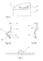
- FIG. 5 shows a vehicle door, having a fixed window 51 and a glass, or panel, movable 52, sliding horizontally.
- the glass assembly fixed + movable glass can be attached, as a whole, for example by gluing, on the door casing 53.
- the movable window 52 is mounted on a hinge member, or toggle, as illustrated in Figures 6A and 6B.
- the knee brace 61 can move in translation, for example using an endless screw 62.
- a seal 71 illustrated in FIG. 7, which is a partial section along the axis AA (FIG. 5), ensures on the one hand sealing, and on the other hand stopping the window mobile, when in the closed position.
- FIGS. 8A and 8B show the drive mechanism, respectively when the movable window is in the closed position and in the open, according to a particular embodiment.
- the motor 81 drives an endless screw 62, acting on the toggle 61.
- the stop 84 interrupts the translation of the toggle joint, the movement of translation then transforming into a rotation.
- the movable window 52 In the open position (FIG. 8B), the movable window 52 is preferably pressed against the fixed window 51, with damping by the seal 71. This allows avoid vibrations, shocks, deterioration, ...
- This plating is ensured by a reverse rotation of the motor 81, the nut of the knee lifter being stopped in translation, for example using a cable 82 driven by a pulley 83 with spring, which is blocked to interrupt its rotation.
- the operation can then be as follows.
- the window 52 being closed, we activates the rotation of the motor 81 clockwise.
- the glass shifts by its housing, then replaces in translation.
- the engine is stopped 81, then the pulley 83 is blocked, and the motor 81 is actuated anti-clockwise.
- the movable window then presses against the fixed window.
- the closure is obtained by unlocking the pulley 83, then by actuating the motor 81 counterclockwise.
Abstract
Description
Le domaine de l'invention est celui des baies de véhicules automobiles. Plus précisément, l'invention concerne les dispositifs d'obturation d'une baie ménagée dans la carrosserie d'un véhicule, et comprenant une partie mobile coulissante, susceptible de libérer ou de fermer une ouverture.The field of the invention is that of motor vehicle bays. More specifically, the invention relates to shutter devices for a bay formed in the body of a vehicle, and comprising a movable part sliding, capable of releasing or closing an opening.
Classiquement, pour obturer la baie d'un véhicule, qu'il s'agisse d'une automobile, d'un véhicule utilitaire, d'un camion, d'un autobus ou d'un wagon de chemin de fer, on rapporte une vitre, maintenue par un cadre de liaison. Ce dernier présente une partie interne et une partie externe, qui viennent pincer simultanément les bords de la glace et de l'ouverture ménagée dans la carrosserie, avec une garniture d'étanchéité.Conventionally, to close the bay of a vehicle, whether it is a automobile, utility vehicle, truck, bus or railcar railway, a window is brought back, held by a connecting frame. This the latter has an internal part and an external part, which pinch simultaneously the edges of the glass and the opening in the bodywork, with a seal.
La technique la plus couramment répandue pour l'ouverture et la fermeture des vitres est de rendre celle-ci mobile verticalement dans son propre plan, en la faisant pénétrer ou sortir du caisson ou de la garniture des portières latérales.The most widely used technique for opening and closing windows is to make it vertically movable in its own plan, making it enter or exit the box or the door trim side.
Cette technique est aujourd'hui couramment utilisée et des solutions pour l'automatiser sont connues. L'équipement des automobiles en vitres électriques est aujourd'hui très répandu.This technique is commonly used today and solutions for automate it are known. The equipment of automobiles in electric windows is very widespread today.
Cette technique présente cependant de nombreux inconvénients. Les moyens d'actionnement et d'entraínement sont lourds, encombrants et complexes à monter. Les portes qui en résultent présentent en conséquence un volume important, nuisant au volume disponible à l'intérieur du véhicule (largeur aux coudes notamment).However, this technique has many drawbacks. The actuation and drive means are heavy, bulky and complex to assemble. The resulting doors therefore have a large volume, affecting the volume available inside the vehicle (width at the elbows in particular).
Elles ont de plus un coût de fabrication élevé et posent classiquement des problèmes d'étanchéité. La maintenance est également complexe. Elles imposent en outre des contraintes sur le plan de l'esthétique et de l'ergonomie.They also have a high manufacturing cost and conventionally pose sealing problems. Maintenance is also complex. They impose in addition, constraints in terms of aesthetics and ergonomics.
Une autre technique a été proposée par le titulaire de la présente demande de brevet. Cette technique est notamment décrite dans les documents de brevet EP - 0 778 168 et EP - 0 857 844. Le dispositif d'obturation (appelé par la suite "baie flush") présenté dans ces documents comprend un ensemble fixe et une partie mobile par rapport à cet ensemble fixe. La partie mobile est reliée à l'ensemble fixe par des éléments fonctionnels qui assurent la mobilité requise et qui sont rapportés sur la face de la partie fixe tournée vers l'intérieur du véhicule.Another technique has been proposed by the holder of this request patent. This technique is described in particular in patent documents EP - 0 778 168 and EP - 0 857 844. The shutter device (hereinafter called "flush bay") presented in these documents includes a fixed assembly and a movable part with respect to this fixed assembly. The mobile part is connected to the whole fixed by functional elements which ensure the required mobility and which are attached to the face of the fixed part facing the interior of the vehicle.
Une telle baie flush peut être montée intégralement indépendamment du véhicule, et rapportée, depuis l'extérieur, dans le logement défini à cet effet sur la carrosserie du véhicule. Elle peut également être solidarisée, en particulier par collage à la partie inférieure d'une portière, selon la technique décrite dans le document de brevet EP 1 022 172. On résout ainsi la plupart des problèmes identifiés plus haut.Such a flush bay can be mounted entirely independently of the vehicle, and brought from the outside into the housing defined for this purpose on the vehicle body. It can also be joined together, in particular by bonding to the lower part of a door, using the technique described in patent document EP 1 022 172. This solves most of the problems identified above.
Sur le plan esthétique, la baie flush présente, vue de l'extérieur, un aspect lisse, affleurant, du fait qu'aucun cadre n'est nécessaire.From an aesthetic point of view, the flush bay looks, from the outside, an aspect smooth, flush, because no frame is necessary.
Le mouvement de la partie mobile peut être, par exemple, basculant ou coulissant. On décrit ci-après, rapidement, un exemple de ce dernier cas.The movement of the mobile part can be, for example, tilting or sliding. An example of this latter case is described briefly below.
Pour assurer un coulissement de la partie mobile, constitué généralement par un panneau transparent, les moyens fonctionnels comprennent un dispositif de guidage comportant un premier et un second rails de guidage montés fixes sur l'ensemble fixe de la baie, de part et d'autre de l'ouverture fermée par le panneau mobile. Celui-ci est monté sur les rails, pour coulisser selon une direction longitudinale, dans un plan de coulissement entre une (ou plusieurs) position d'ouverture et une position intermédiaire de dégagement dans laquelle il est en regard de la baie et dégagé de celle-ci.To ensure sliding of the movable part, generally consisting by a transparent panel, the functional means comprise a device guide comprising first and second guide rails fixedly mounted on the fixed bay assembly, on either side of the opening closed by the panel mobile. This is mounted on the rails, to slide in one direction longitudinal, in a sliding plane between one (or more) position opening and an intermediate release position in which it is in look of the bay and clear of it.
Des moyens d'articulation assurent la liaison du panneau avec les rails de guidage de façon à permettre un déplacement transversal du panneau entre sa position intermédiaire de dégagement dans laquelle il est en regard et en retrait transversal de la baie, et sa position d'obturation dans laquelle il est enchâssé dans la baie.Hinge means ensure the connection of the panel with the rails of guide so as to allow transverse movement of the panel between its intermediate release position in which it is opposite and recessed transverse of the bay, and its closed position in which it is embedded in the Bay.
Le panneau mobile passe ainsi du plan formé par l'ensemble fixe (position d'obturation) à un plan sensiblement parallèle de coulissement, et réciproquement. The movable panel thus passes from the plane formed by the fixed assembly (closed position) to a substantially parallel plane of sliding, and reciprocally.
L'invention se rapporte notamment à ce type de dispositif d'obturation, à ses variantes et ses perfectionnements. Ainsi, l'invention peut s'appliquer à tous les dispositifs d'obturation dont la cinématique d'ouverture et/ou de fermeture inclut un déplacement (y) entre une position d'ouverture et une position intermédiaire de dégagement, dans un plan parallèle au plan de l'ensemble fixe, et un déplacement (x) dans ce plan parallèle.The invention relates in particular to this type of closure device, to its variants and improvements. Thus, the invention can be applied to all shutter devices including the opening and / or closing kinematics includes displacement (y) between an open position and a position intermediate release, in a plane parallel to the plane of the fixed assembly, and a displacement (x) in this parallel plane.
Cette clé de composition de mouvements de déplacement longitudinal et d'enchâssement transversal est particulièrement avantageuse, car elle permet une ouverture du panneau le long du véhicule (par exemple parallèlement au flanc de celui-ci) tout en assurant à la fermeture, un enchâssement du panneau dans la baie.This composition key for longitudinal displacement movements and of transverse embedding is particularly advantageous, because it allows a opening of the panel along the vehicle (for example parallel to the side of this one) while ensuring at closing, an embedding of the panel in the bay.
Dans le mode de réalisation décrit dans le brevet EP - 0 857 844, le panneau est manoeuvré à l'aide d'une poignée pouvant être fixée sur la partie inférieure du panneau. Plusieurs techniques ont été proposées pour réaliser et mettre en oeuvre cette poignée. Cependant, en général, les manoeuvres d'ouverture et de fermeture de ce type de dispositif d'obturation s'effectuent actuellement de façon manuelle.In the embodiment described in patent EP-0 857 844, the panel is operated using a handle which can be fixed on the part bottom of the panel. Several techniques have been proposed for making and implement this handle. However, in general, the maneuvers opening and closing of this type of closure device currently manually.
L'automatisation, et donc la motorisation, des baies flush est bien sûr souhaitable, sinon nécessaire, pour équiper des véhicules modernes. Le principe de la motorisation a donc été envisagé. Cependant, aucune solution efficace n'a pour l'instant été proposée.The automation, and therefore the motorization, of flush bays is of course desirable, if not necessary, to equip modern vehicles. The principle motorization has therefore been envisaged. However, no effective solution has so far been offered.
Une des raisons techniques à ce problème est que l'automatisation de la succession de déplacements (mouvement en x, puis en y) est beaucoup plus complexe que la mise en oeuvre d'un mouvement dans un seul plan, tel que cela est le cas lorsque la vitre pénètre dans la portière.One of the technical reasons for this problem is that the automation of the succession of displacements (movement in x, then in y) is much more complex as the implementation of a movement in a single plane, such as this is the case when the window enters the door.
On est donc conduit à prévoir des moyens spécifiques pour effectuer chacun des mouvements en x et en y, ce qui conduit à des montages complexes, coûteux et encombrants, et donc inadaptés.We are therefore led to provide specific means for carrying out each of the movements in x and in y, which leads to complex assemblies, expensive and bulky, and therefore unsuitable.
Le problème de l'encombrement (et du poids) est essentiel, dans le cas des baies flush : on ne peut pas dissimuler tout ou partie des moyens d'actionnement dans le caisson inférieur de la portière, que l'on souhaite conserver fermé. L'essentiel de la surface de la baie est donc visible, et il n'est pas envisageable que des moyens mécaniques (moteur, tringlerie, ...) soient apparents et/ou occupent une surface et un volume importants.The problem of space (and weight) is essential, in the case flush berries: you cannot hide all or part of the means actuation in the lower casing of the door, as desired keep closed. Most of the surface of the bay is therefore visible, and it is not not possible that mechanical means (engine, linkage, ...) are visible and / or occupy a large surface and volume.
Par ailleurs, les baies doivent rester aisées à fabriquer, à livrer et à monter, ce qui est généralement peu compatible avec la notion d'automatisation.In addition, the berries must remain easy to manufacture, deliver and go up, which is generally not very compatible with the concept of automation.
On notera qu'il a été envisagé de combiner les deux mouvements, sous la forme d'un mouvement louvoyant, selon lequel le bord distal de la parie mobile se trouve, en fin de course, dans le plan de la baie (la partie mobile étant alors « en travers », entre le plan d'obturation et le plan de coulissement). Il suffit alors de ramener, manuellement, le bord proximal pour assurer l'obturation.It will be noted that it has been envisaged to combine the two movements, under the form of a swaying movement, according to which the distal edge of the movable bet is, at the end of the race, in the bay plan (the mobile part then being "Crosswise", between the obturation plane and the sliding plane). It is enough then to bring back, manually, the proximal edge to ensure the obturation.
On n'obtient cependant pas une obturation complètement automatisée, à moins de prévoir des moyens complémentaires, ce qui ramène aux problèmes cités plus hauts.You do not get a fully automated shutter, however. less to plan additional resources, which brings back to the problems cited above.
L'invention ne vise cependant pas ce type de dispositifs à mouvement louvoyant, qui posent de nombreux problèmes, notamment en termes d'étanchéité et d'esthétique, du fait que le jeu entre le panneau mobile et l'ouverture dans l'ensemble fixe doit être important à l'arrière.The invention does not, however, target this type of movement device. swaying, which pose many problems, especially in terms sealing and aesthetics, because the clearance between the movable panel and the opening in the fixed assembly must be large at the rear.
L'invention concerne donc les dispositifs dans lesquels la cinématique est décomposée en deux mouvements (en x puis en y), le panneau mobile restant en permanence sensiblement parallèle « à lui-même », ou, plus exactement, au plan défini par la baie. En d'autres termes, le panneau mobile passe dans une pluralité de plans, tous sensiblement parallèles.The invention therefore relates to devices in which the kinematics is broken down into two movements (in x then in y), the movable panel remaining in permanence substantially parallel "to itself", or, more exactly, to the plane defined by the bay. In other words, the movable panel passes in a plurality planes, all substantially parallel.
Le terme « sensiblement » signifie qu'il peut y avoir des jeux, des décalages ou des déplacements qui ne sont pas parfaitement rectilignes, du fait de la structure et de la forme de la baie et du véhicule, des matériaux, des tolérances, de l'usure, ... Il n'englobe pas en revanche le cas d'un panneau « en travers » dans un dispositif louvoyant.The term "substantially" means that there may be games, shifts or displacements that are not perfectly straight, due to the structure and shape of the rack and the vehicle, materials, tolerances, wear, ... However, it does not include the case of a panel "in travers ”in a swinging device.
On notera par ailleurs que le terme « plan » doit ici s'entendre dans une acception élargie : le plan formé par la baie est généralement courbe, selon une, voire deux, directions (cela peut justifier également, dans certains cas, le terme « sensiblement »).Note also that the term "plan" should be understood here in a extended meaning: the plane formed by the bay is generally curved, according to one, or even two, directions (this may also justify, in some cases, the term "Substantially").
L'invention a donc notamment pour objectif de pallier les inconvénients de l'art antérieur cités ci-dessus.The invention therefore particularly aims to overcome the drawbacks of the prior art cited above.
Plus précisément, l'invention a pour objectif de proposer un dispositif d'obturation d'une baie intégrant un panneau mobile, restant en permanence sensiblement parallèle au plan formé par la baie, et dont la manoeuvre est automatisée.More specifically, the invention aims to provide a device shutter of a bay integrating a movable panel, remaining permanently substantially parallel to the plane formed by the bay, and whose operation is automated.
L'invention a également pour objectif de fournir un tel dispositif d'obturation d'une baie qui assure un enchâssement complet et simultané du panneau dans la baie lors d'une manoeuvre de fermeture.The invention also aims to provide such a device shutter of a bay which ensures a complete and simultaneous embedding of the panel in the bay during a closing operation.
L'invention a encore pour objectif de fournir un tel dispositif d'obturation d'une baie qui soit simple à réaliser, à monter sur une portière ou sur un véhicule, et qui permette une utilisation aisée et fiable.The invention also aims to provide such a shutter device a bay that is simple to make, to mount on a door or on a vehicle, and which allows easy and reliable use.
Un autre objectif de l'invention est de fournir un tel dispositif d'obturation d'une baie qui conserve l'ensemble des avantages des "baies flush" déjà développées par le titulaire de la présente demande, et notamment :
- aspect esthétique affleurant ;
- aspects aérodynamiques ;
- facilité et coût réduit de fabrication ;
- facilité et coût réduit de montage.
- flush aesthetic appearance;
- aerodynamic aspects;
- ease and reduced cost of manufacture;
- ease and reduced cost of assembly.
Ces objectifs, ainsi que d'autres qui apparaítront par la suite, sont atteints à l'aide d'un dispositif d'obturation d'une baie ménagée dans la carrosserie d'un véhicule automobile, comprenant un ensemble fixe destiné à être rapporté sur ladite carrosserie et une partie mobile par rapport audit ensemble fixe, monté sur au moins un élément de support et/ou de guidage solidaire de la face dudit ensemble fixe dirigée vers l'intérieur dudit véhicule, et pouvant venir obturer ou libérer une ouverture ménagée dans ledit ensemble fixe. Selon l'invention, le dispositif comprend des moyens de motorisation uniques agissant sur au moins un élément coulissant le long d'un desdits éléments de support et/ou de guidage et présentant une articulation, de façon à assurer une cinématique dudit panneau mobile par rapport audit ensemble fixe décomposée en deux déplacements perpendiculaires :
- un déplacement (y) de verrouillage/déverrouillage, sensiblement perpendiculaire au plan formé par ledit ensemble fixe, et permettant le passage d'une position d'obturation dans le plan formé par ledit ensemble fixe à une position d'ouverture, dans un plan d'ouverture, sensiblement parallèle audit plan formé par ledit ensemble fixe, et réciproquement, ledit déplacement (y) de verrouillage/déverrouillage étant obtenu en agissant sur la ou lesdites articulations ;
- un déplacement (x) de coulissement dans ledit plan d'ouverture, obtenu en entraínant le ou lesdits éléments coulissants.
- a locking / unlocking movement (y), substantially perpendicular to the plane formed by said fixed assembly, and allowing passage from a closed position in the plane formed by said fixed assembly to an open position, in a plane d opening, substantially parallel to said plane formed by said fixed assembly, and vice versa, said displacement (y) of locking / unlocking being obtained by acting on said articulation (s);
- a sliding movement (x) in said opening plane, obtained by driving the said sliding element or elements.
Ainsi, on décompose la cinématique en deux mouvements perpendiculaires, ou quasi-perpendiculaires, sans louvoiement ni phase transitoire, à l'aide d'un unique moteur, de façon simple et efficace.Thus, we break down the kinematics into two movements perpendicular, or almost perpendicular, without darting or phase transient, using a single motor, simply and efficiently.
De façon avantageuse, lesdits moyens de motorisation agissent sur des moyens d'entraínement assurant ledit déplacement de coulissement, jusqu'à une butée interrompant ce coulissement, lors de l'obturation de ladite ouverture, lorsque ledit panneau fixe se trouve en regard de ladite ouverture, l'énergie appliquée auxdits moyens d'entraínement étant alors transférée à la ou auxdites articulations pour ramener ledit panneau mobile en position d'obturation.Advantageously, said motorization means act on drive means ensuring said sliding movement, up to a stop interrupting this sliding, when closing said opening, when said fixed panel is opposite said opening, the energy applied to said drive means then being transferred to said one or more joints to return said movable panel to the closed position.
Selon un premier mode de réalisation, ledit élément coulissant comprend avantageusement un premier profilé solidaire dudit panneau mobile et un second profilé solidaire dudit rail, reliés au niveau de ladite articulation, lesdits premier et second profilés étant sélectivement solidarisés ou désolidarisés en translation, de façon à interrompre le déplacement en translation dudit premier profilé, lors de l'obturation de ladite ouverture, lorsque le panneau mobile se trouve en regard de ladite ouverture, ledit second profilé continuant son déplacement en translation sur une portion supplémentaire dudit rail. According to a first embodiment, said sliding element comprises advantageously a first section integral with said movable panel and a second section integral with said rail, connected at the level of said articulation, said first and second sections being selectively secured or separated in translation, so as to interrupt the translational movement of said first profile, when the closure of said opening, when the movable panel is opposite of said opening, said second profile continuing its movement in translation on an additional portion of said rail.
Ladite portion supplémentaire dudit rail peut avantageusement porter une came ou une rampe, entraínant une rotation dudit second profilé, de façon à agir sur ladite articulation pour ramener ledit panneau mobile dans ladite position d'obturation.Said additional portion of said rail can advantageously carry a cam or a ramp, causing a rotation of said second profile, so as to act on said articulation to return said movable panel to said position shutter.
Préférentiellement, ledit premier profilé est arrêté en translation à l'aide d'une butée agissant sur ledit premier profilé et/ou sur ledit panneau mobile.Preferably, said first profile is stopped in translation using a stop acting on said first profile and / or on said movable panel.
De façon avantageuse, ledit panneau mobile se place dans ledit plan d'ouverture sous l'effet de son propre poids, lorsqu'il n'est pas maintenu en position d'obturation.Advantageously, said movable panel is placed in said plane due to its own weight, when it is not kept in shutter position.
Selon un deuxième mode de réalisation, lesdits moyens de motorisation uniques transmettent un couple à ladite articulation lorsque ledit panneau est en regard de ladite baie, pour ramener ledit panneau mobile dans ladite position d'obturation.According to a second embodiment, said motorization means single transmit torque to said joint when said panel is in look of said bay, to bring said movable panel into said position shutter.
Dans ce cas, lesdits moyens de motorisation agissent préférentiellement sur un système vis sans fin/écrou, ledit écrou étant formé sur et/ou solidaire d'au moins un élément solidaire dudit panneau mobile, ledit déplacement de coulissement correspondant à un déplacement dudit écrou sur ladite vis, et ledit déplacement de verrouillage/déverrouillage correspondant à une position bloquée dudit écrou sur ladite vis.In this case, said motorization means preferably act on a worm / nut system, said nut being formed on and / or integral with at at least one element secured to said movable panel, said displacement of sliding corresponding to a displacement of said nut on said screw, and said locking / unlocking movement corresponding to a locked position of said nut on said screw.
Selon un troisième mode de réalisation selon lequel le dispositif d'obturation comprend deux éléments de support et/ou de guidage, lesdits moyens de motorisation agissent avantageusement sur l'élément de support et/ou de guidage inférieur, l'élément de support et/ou de guidage supérieur étant passif.According to a third embodiment according to which the device shutter comprises two support and / or guide elements, said elements motorization means act advantageously on the support element and / or guide, the support and / or upper guide element being passive.
Selon une approche avantageuse, le dispositif peut comprendre un unique élément de support et/ou de guidage. Cette approche est bien adaptée notamment à une nouvelle structure, selon laquelle ledit panneau mobile présente au moins un bord et/ou un angle commun avec un bord et/ou un angle dudit dispositif d'obturation.According to an advantageous approach, the device can comprise a single support and / or guide element. This approach is well suited, in particular to a new structure, according to which said movable panel has at least an edge and / or an angle common with an edge and / or an angle of said device shutter.
Selon une caractéristique particulière (notamment bien adaptée aux mécanismes à rail unique), le dispositif d'obturation comprend avantageusement des moyens de maintien de façon stable dudit panneau mobile, dans une position d'ouverture prédéterminée.According to a particular characteristic (particularly well suited to single rail mechanisms), the closure device advantageously comprises means for stably holding said movable panel in a position of predetermined opening.
Lesdits moyens de maintien peuvent notamment plaquer ledit panneau mobile contre ledit ensemble fixe. De façon avantageuse, lesdits moyens de maintien sont formés et/ou actionnés par lesdits moyens de motorisation.Said holding means can in particular press said panel movable against said fixed assembly. Advantageously, said means of maintenance are formed and / or actuated by said motorization means.
Selon un mode de réalisation préférentiel, lesdits moyens de maintien agissent de façon à interrompre le coulissement dudit panneau mobile et à inverser le sens de rotation desdits moyens de motorisation.According to a preferred embodiment, said holding means act so as to interrupt the sliding of said movable panel and to reverse the direction of rotation of said motorization means.
De façon avantageuse, au moins une partie des bords de ladite partie mobile est équipée d'un joint, assurant l'étanchéité dans ladite position d'obturation et formant amortisseur dans ladite position d'ouverture prédéterminée.Advantageously, at least part of the edges of said part mobile is equipped with a seal, ensuring sealing in said position shutter and damper forming in said open position predetermined.
Selon plusieurs techniques avantageuses, lesdits moyens de motorisation agissent sur l'un des moyens de transmission appartenant au groupe comprenant :
- les crémaillères ;
- les câbles ;
- les vis sans fin ;
- les tambours à rainure hélicoïdale,
- racks;
- cables ;
- the worms;
- helical groove drums,
Dans le cas où on met en oeuvre une vis sans fin, cette dernière est avantageusement une vis souple, notamment lors que le dispositif d'obturation n'est pas plat.In the case where a worm is used, the latter is advantageously a flexible screw, especially when the closure device is not flat.
Préférentiellement, lesdits moyens de motorisation uniques sont solidarisés audit ensemble fixe. De façon avantageuse, ils sont montés dans et/ou sur un desdits éléments de support et/ou de guidage.Preferably, said single motorization means are joined to said fixed assembly. Advantageously, they are mounted in and / or on one of said support and / or guide elements.
Selon une autre caractéristique, ladite baie est ménagée dans un panneau vitré.According to another characteristic, said bay is formed in a panel window.
L'invention concerne également les véhicules automobiles comprenant au moins un dispositif d'obturation tel que décrit ci-dessus.The invention also relates to motor vehicles comprising at least minus a sealing device as described above.
D'autres caractéristiques et avantages de l'invention apparaítront plus clairement à la lecture de la description suivante de plusieurs modes de réalisation préférentiels de l'invention, donnés à titre d'exemples illustratifs et non limitatifs, et des dessins parmi lesquels :
- la figure 1présente un exemple de baie flush à panneau coulissant, d'un type connu en soi ,
- la figure 2 illustre les articulations, ou genouillères, mises en oeuvre dans le dispositif de la figure 1 ;
- la figure 3 présente, de façon schématique, un premier mode de réalisation de l'invention, selon lequel le panneau mobile est entraíné par une vis sans fin, en translation puis en rotation ;
- la figure 4 illustre un autre mode de réalisation de l'invention, mettant toujours en oeuvre une vis sans fin, et dans lequel les éléments de la genouillère sont désolidarisables ;
- la figure 5 présente une autre structure de dispositif d'obturation , dans lequel le panneau mobile est réalisé dans un angle ;
- les figures 6A et 6B illustrent schématiquement le mécanisme d'entraínement du panneau mobile de la figure 5, mettant en oeuvre un rail unique ;
- la figure 7 est une coupe AA de la figure 5, montrant le joint d'étanchéité ;
- les figures 8A et 8B présentent le fonctionnement motorisé du dispositif de la figure 5.
- FIG. 1 shows an example of a flush bay with a sliding panel, of a type known per se,
- Figure 2 illustrates the joints, or knee pads, implemented in the device of Figure 1;
- Figure 3 shows, schematically, a first embodiment of the invention, according to which the movable panel is driven by an endless screw, in translation then in rotation;
- FIG. 4 illustrates another embodiment of the invention, always using an endless screw, and in which the elements of the toggle joint can be separated;
- FIG. 5 shows another structure of a shutter device, in which the movable panel is produced at an angle;
- Figures 6A and 6B schematically illustrate the drive mechanism of the movable panel of Figure 5, implementing a single rail;
- Figure 7 is a section AA of Figure 5 showing the seal;
- FIGS. 8A and 8B show the motorized operation of the device of FIG. 5.
Comme déjà indiqué, le principe général de l'invention repose notamment sur l'utilisation de moyens de motorisation uniques assurant d'une part le coulissement (ou, dans un mode de réalisation particulier, la rotation) de la partie mobile, dans un plan d'ouverture, et d'autre part le passage du plan d'ouverture au plan d'obturation. L'invention propose donc de mettre en oeuvre sélectivement des mouvements dans deux directions perpendiculaires (ou quasi-perpendiculaires), avec une motorisation unique, et des moyens d'actionnement très simples.As already indicated, the general principle of the invention is based in particular on the use of unique motorization means ensuring a apart the sliding (or, in a particular embodiment, the rotation) of the mobile part, in an opening plane, and on the other hand the passage of the plane opening to the shutter plan. The invention therefore proposes to implement selectively movements in two perpendicular (or quasi-perpendicular) directions, with a single motorization, and actuation means very simple.
On décrit ci-après quatre exemples de mise en oeuvre, résidant tous sur le même principe : des moyens spécifiques (cale, butée, blocage d'écrou, ...) sont utilisés pour changer le mouvement de la partie mobile, sans action spécifique sur les moyens d'entraínement, qui tournent en permanence de la même façon.Four examples of implementation are described below, all residing on the same principle: specific means (block, stop, nut blocking, ...) are used to change the movement of the moving part, without specific action on the drive means, which rotate continuously in the same way.
Selon ce mode de réalisation, on motorise une baie telle que décrite dans le document de brevet déjà cité EP-0 778 168. On rappelle tout d'abord le principe correspondant, à l'aide des figures 1 et 2.According to this embodiment, a rack is motorized as described in the patent document already cited EP-0 778 168. We first recall the corresponding principle, using Figures 1 and 2.
Le dispositif d'obturation d'une baie de la figure 1 comprend un panneau
11 coulissant, mobile le long de rails de guidage 12a, 12b, entre des positions
d'obturation et d'ouverture d'une ouverture 13 ménagée dans un élément fixe 14
destiné à être rapporté sur la carrosserie d'un véhicule, pour obturer une baie
ménagée sur celle-ci.The shutter device of a bay of Figure 1 comprises a
Comme illustré par la figure 2, le panneau 11 est relié aux rails de
guidage par l'intermédiaire d'organes d'articulation 25 et 26.As illustrated in FIG. 2, the
Ces organes d'articulation 25 et 26 permettent d'assurer le déplacement
du panneau 11 d'une position où il est engagé dans la baie (position d'obturation)
vers une position intermédiaire de dégagement (position d'ouverture) où il est en
regard de la baie et légèrement en retrait de celle-ci, et inversement.These
Chaque organe d'articulation 25, 26 est formé de deux éléments, par
exemple des profilés, solidarisés par un axe A1, A2 formant articulation. Le
premier élément 251, 261 est solidaire de la partie fixe. Plus précisément, le
second élément est monté dans un des rails 12a, 12b respectivement, dans lequel
il peut coulisser.Each
En agissant sur un des organes d'articulation 25, 26 au niveau de
l'articulation (de façon à ouvrir l'angle formé par chacun des éléments), on
déplace la partie mobile 11 perpendiculairement au plan défini par l'ensemble
fixe 14. On réalise ainsi l'enchâssement de la partie mobile dans la partie fixe, et
donc l'obturation de l'ouverture.By acting on one of the
L'obturation est assurée tant que l'action sur l'organe d'articulation est maintenue. Lorsqu'elle est relâchée, le panneau mobile revient de lui-même dans le plan de coulissement ; Il est alors possible de la déplacer le long des rails (flèche C), dans la position souhaitée.The obturation is ensured as long as the action on the articulation organ is maintained. When released, the movable panel will return on its own in the sliding plane; It is then possible to move it along the rails (arrow C), in the desired position.
On met donc en oeuvre une cinématique dudit panneau mobile par rapport audit ensemble fixe, décomposée en deux déplacements :
- un déplacement de verrouillage/déverrouillage, sensiblement
perpendiculaire au plan formé par l'ensemble
fixe 14, et permettant le passage du plan formé par l'ensemblefixe 14 à un plan de coulissement, sensiblement parallèle au plan formé par l'ensemblefixe 14, et réciproquement ; - un déplacement de coulissement dans le plan de coulissement.
- a locking / unlocking movement, substantially perpendicular to the plane formed by the fixed
assembly 14, and allowing the passage from the plane formed by the fixedassembly 14 to a sliding plane, substantially parallel to the plane formed by the fixedassembly 14, and reciprocally ; - a sliding movement in the sliding plane.
Bien entendu, de nombreuses variantes de réalisation et de nombreux perfectionnements existent ou sont envisageables (ensemble fixe en plusieurs parties, rails non parallèles, joints spécifiques, ...) et peuvent être mis en oeuvre dans le cadre de la présente invention.Of course, many variants and many improvements exist or are possible (set fixed in several parts, non-parallel rails, specific seals, ...) and can be used work in the context of the present invention.
L'invention propose donc d'assurer la motorisation de ces deux
déplacements perpendiculaires à l'aide d'un moyen de motorisation unique.
Ce dernier assure donc le coulissement du panneau mobile, dans le plan de
coulissement, en entraínant l'élément 262 de l'organe d'articulation.The invention therefore proposes to ensure the motorization of these two
perpendicular movements using a single motorized means.
The latter therefore ensures the sliding of the movable panel, in the plane of
sliding, driving the
Lors de la fermeture, des moyens d'arrêt sont prévus pour interrompre
le coulissement lorsque le panneau mobile se trouve en face de l'ouverture.
L'énergie appliquée par les moyens de motorisation sur l'élément 262 est
alors convertie en un couple, qui entraíne la rotation de ce dernier, et par
conséquent le déplacement du panneau mobile jusqu'à sa position
d'obturation.When closing, stop means are provided to interrupt
sliding when the movable panel is opposite the opening.
The energy applied by the motorization means to the
Comme déjà mentionné, le retour en position d'ouverture se fait généralement sous le seul effet du poids, lorsque le couple n'est plus appliqué (et/ou que des moyens de verrouillage sont déverrouillés). Des moyens d'entraínement, de guidage et/ou de ralentissement du mouvement peuvent être prévus.As already mentioned, the return to the open position is done usually under the sole effect of weight, when the torque is no longer applied (and / or that locking means are unlocked). Means training, guiding and / or slowing movement can be planned.
Ainsi que cela est illustré schématiquement en figure 3, l'entraínement
peut avantageusement être assuré à l'aide d'une vis sans fin 31, actionnée en
rotation par un moteur 32.As shown schematically in Figure 3, the drive
can advantageously be ensured using a
L'élément 262 de l'organe d'articulation présente un alésage fileté,
coopérant avec la vis sans fin. Ainsi, lorsque le moteur entraíne la vis 31 en
rotation (le panneau mobile étant dans le plan de coulissement), l'élément 262
se déplace le long du pas de vis et, par conséquent, le panneau mobile 11
coulisse (33) le long de la partie fixe.
Lors de la fermeture, l'élément 262 se déplace longitudinalement
jusqu'à une butée 34, qui correspond à la position en regard de l'ouverture
pour le panneau mobile. Cet élément 262 ne peut alors plus progresser le long
de la vis 31. Cette dernière continuant à tourner, l'élément 262 est entraíné en
rotation (35).When closing, the
Cette rotation ramène, via l'élément 261, le panneau mobile 11 dans la
position d'obturation (c'est-à-dire enchâssé dans l'ensemble fixe).This rotation brings back, via
La butée 34 peut être une cale montée sur le rail, et agissant
directement sur l'élément 262. On peut également prévoir des moyens réalisés
ou montés sur la vis elle-même, tels qu'un ou plusieurs ergots venant s'inscrire
dans des logements correspondants de l'élément 262 (cela permettant par
ailleurs de contrôler également l'ouverture du panneau).The
Avantageusement, la vis 231 est réalisée dans un matériau souple, notamment lorsque la baie présente une forme galbée.Advantageously, the screw 231 is made of a flexible material, especially when the bay has a curved shape.
Bien entendu, d'autres types d'entraínement peuvent être mis en oeuvre.Of course, other types of training can be implemented.
Par exemple, la vis sans fin peut être remplacée par un tambour portant
une rainure hélicoïdale dans laquelle se déplace un ergot formé dans l'élément
262. L'extrémité de la rainure correspond à la fin du coulissement: le tambour
entraíne alors l'ergot, et donc l'élément 262, en rotation, pour assurer la
fermeture.For example, the worm can be replaced by a bearing drum
a helical groove in which a lug formed in the element moves
262. The end of the groove corresponds to the end of the slide: the drum
then drives the lug, and therefore the
Selon une autre approche, on peut prévoir que les éléments 261 et 262
sont désolidarisables en coulissement. Ils sont donc liés lors du déplacement
assurant le coulissement, pour que le déplacement de l'élément 262 entraíne celui
du panneau mobile, et désolidarisés en translation lors du déplacement
perpendiculaire de fermeture, selon le principe illustré en figure 4.According to another approach, it can be foreseen that the
Une butée 41 est prévue pour arrêter l'élément 261 solidaire du panneau
mobile (et/ou le panneau mobile lui-même). Lors de la fermeture, lorsqu'il atteint
cette butée 41, l'élément 261 est arrêté, et maintient la partie mobile 11 en regard
de l'ouverture. En revanche, l'élément 262 continue son déplacement, sous
l'action des moyens de motorisation et, par exemple, de la vis sans fin.A
Une came (non représentée), ou un moyen similaire, agit sur cet élément
262, de façon que, simultanément à sa translation 43, il se redresse, par un
mouvement de rotation 44 agissant ainsi sur l'articulation et, par conséquent, sur
le panneau mobile 11.A cam (not shown), or a similar means, acts on this
Il est à noter que, malgré la présence d'une came, ou d'un plan incliné,
agissant progressivement sur l'élément 262 par ailleurs en translation, on obtient
bien un mouvement perpendiculaire à l'axe de coulissement pour le panneau
mobile, du fait de la désolidarisation en translation des deux éléments 261 et 262
de l'organe d'articulation. La désolidarisation, et la solidarisation, des deux
éléments sont assurés par exemple à l'aide d'un ressort de compression.It should be noted that, despite the presence of a cam, or an inclined plane,
acting progressively on
Selon cette approche, les moyens d'entraínement de l'élément 262
peuvent être variés. Outre ceux déjà exposés, on peut notamment mettre en
oeuvre des systèmes à crémaillère, à câble, ...According to this approach, the means for driving the
Dans certains cas, il n'est pas possible, ou pas souhaitable, de prévoir deux rails pour maintenir et/ou guider le panneau mobile. C'est par exemple le cas pour des panneaux mobiles de petite taille, et/ou réalisés dan un angle ou un bord de l'ensemble fixe (le panneau mobile forme, lorsqu'il est fermé, un bord ou un angle de la baie). Cette technique fait l'objet d'une demande de brevet conjointe, ayant pour titre « Dispositif d'obturation d'une baie ménagée dans un véhicule automobile, à rail unique, et véhicule correspondant ».In some cases, it is not possible, or not desirable, to plan two rails to hold and / or guide the movable panel. This is for example the case for small mobile panels, and / or made at an angle or edge of the fixed assembly (the movable panel forms, when closed, an edge or an angle of the bay). This technique is the subject of a patent application joint, titled "Device for closing a bay formed in a motor vehicle, single rail, and corresponding vehicle ".
Un exemple d'une telle baie est illustré schématiquement en figure 5.
Cette figure 5 présente une portière de véhicule, présentant une vitre fixe 51 et
une vitre, ou panneau, mobile 52, coulissant horizontalement. L'ensemble vitre
fixe + vitre mobile peut être rapporté, comme un tout, par exemple par collage,
sur le caisson de porte 53.An example of such an opening is illustrated diagrammatically in FIG. 5.
This FIG. 5 shows a vehicle door, having a fixed
La vitre mobile 52 est montée sur un organe d'articulation, ou
genouillère, ainsi que cela est illustré en figures 6A et 6B. La genouillère 61 peut
se déplacer en translation, par exemple à l'aide d'une vis sans fin 62.The
A la fermeture, selon l'une des techniques décrites préalablement, la
rotation 63 imprimée à l'élément 262 (mouvement de genouillère) ramène le
panneau mobile 52 vers sa position de fermeture. Un coin 64 monté sur la vitre
fixe 51 assure le guidage et le « coincement » du panneau mobile (figure 6B)On closing, according to one of the techniques described previously, the
Un joint 71, illustré sur la figure 7, qui est une coupe partielle selon l'axe
AA (figure 5), assure d'une part l'étanchéité, et d'autre part l'arrêt de la vitre
mobile, lorsqu'elle est en position d'obturation.A
Les figures 8A et 8B présentent le mécanisme d'entraínement, respectivement lorsque la vitre mobile est en position fermée et en position ouverte, selon un mode de réalisation particulier.FIGS. 8A and 8B show the drive mechanism, respectively when the movable window is in the closed position and in the open, according to a particular embodiment.
Le moteur 81 entraíne une vis sans fin 62, agissant sur la genouillère 61.
La butée 84 interrompt la translation de la genouillère, le mouvement de
translation se transformant alors en une rotation.The
En position ouverte (figure 8B), la vitre mobile 52 est préférentiellement
plaquée sur la vitre fixe 51, avec un amortissement par le joint 71. Cela permet
d'éviter les vibrations, chocs, détériorations, ... In the open position (FIG. 8B), the
Ce placage est assuré par une rotation inverse du moteur 81, l'écrou de la
genouillère étant arrêté en translation, par exemple à l'aide d'un câble 82
entraíné par une poulie 83 avec ressort, que l'on bloque pour interrompre sa
rotation.This plating is ensured by a reverse rotation of the
Le fonctionnement peut alors être le suivant. La vitre 52 étant fermée, on
actionne la rotation du moteur 81 dans le sens horaire. La vitre se décale de son
logement, puis se replace en translation.The operation can then be as follows. The
Lorsque la vitre mobile a atteint la position souhaitée, on arrête le moteur
81, puis on bloque la poulie 83, et on actionne le moteur 81 dans le sens anti-horaire.
La vitre mobile vient alors se plaquer contre la vitre fixe.When the movable window has reached the desired position, the engine is stopped
81, then the
La fermeture est obtenue en débloquant la poulie 83, puis en actionnant le
moteur 81 dans le sens anti-horaire.The closure is obtained by unlocking the
Les différents modes de réalisation de l'invention décrits ci-dessus ne sont bien sûr pas limitatifs de l'invention. D'autres modes de réalisation, ainsi que des variantes et des perfectionnements, sont envisageables.The various embodiments of the invention described above do not are of course not limiting of the invention. Other embodiments, as well that variants and improvements are possible.
En particulier, bien qu'on ait décrit un décalage du panneau mobile vers l'intérieur du véhicule, il est également possible que celui-ci s'effectue vers l'extérieur.In particular, although an offset has been described from the movable panel towards inside the vehicle, it is also possible that it is carried out towards outside.
Par ailleurs, bien qu'un seul panneau mobile soit représenté, il est bien sûr possible d'un prévoir plusieurs.Furthermore, although only one movable panel is represented, it is good sure possible to provide several.
Enfin, on ne détaille pas les éléments complémentaires ou annexes (joint d'étanchéité, système de verrouillage, dispositif anti-effraction, prolongement des rails jusqu'aux bords du dispositif (cf. figure 1)...), qui pourront bien sûr être intégrés à la baie de l'invention.Finally, we do not detail the additional or annexed elements (attached sealing, locking system, burglar-proof device, extension rails to the edges of the device (see Figure 1) ...), which can of course be integrated into the rack of the invention.
Claims (22)
caractérisé en ce qu'il comprend des moyens de motorisation uniques agissant sur au moins un élément coulissant le long d'un desdits éléments de support et/ou de guidage et présentant une articulation, de façon à assurer une cinématique dudit panneau mobile par rapport audit ensemble fixe décomposée en deux déplacements perpendiculaires :
characterized in that it comprises unique motorization means acting on at least one element sliding along one of said support and / or guide elements and having an articulation, so as to ensure kinematics of said movable panel with respect to said fixed assembly broken down into two perpendicular displacements:
l'énergie appliquée auxdits moyens d'entraínement étant alors transférée à la ou auxdites articulations pour ramener ledit panneau mobile en position d'obturation. Sealing device according to claim 1, characterized in that said motorization means act on drive means ensuring said sliding movement, up to a stop interrupting this sliding, when closing said opening, when said fixed panel is located opposite said opening,
the energy applied to said drive means then being transferred to said joint (s) to return said movable panel to the closed position.
lesdits premier et second profilés étant sélectivement solidarisés ou désolidarisés en translation, de façon à interrompre le déplacement en translation dudit premier profilé, lors de l'obturation de ladite ouverture, lorsque le panneau mobile se trouve en regard de ladite ouverture, ledit second profilé continuant son déplacement en translation sur une portion supplémentaire dudit rail.Sealing device according to any one of claims 1 and 2, characterized in that said sliding element comprises a first profile secured to said movable panel and a second profile secured to said rail, connected at the level of said articulation,
said first and second profiles being selectively secured or disengaged in translation, so as to interrupt the displacement in translation of said first profile, when closing said opening, when the movable panel is opposite said opening, said second profile continuing its displacement in translation on an additional portion of said rail.
ledit déplacement de coulissement correspondant à un déplacement dudit écrou sur ladite vis, et ledit déplacement de verrouillage/déverrouillage correspondant à une position bloquée dudit écrou sur ladite vis.Sealing device according to claim 7, characterized in that said motorization means act on a worm / nut system, said nut being formed on and / or integral with at least one element integral with said movable panel,
said sliding movement corresponding to a movement of said nut on said screw, and said locking / unlocking movement corresponding to a locked position of said nut on said screw.
Applications Claiming Priority (2)
| Application Number | Priority Date | Filing Date | Title |
|---|---|---|---|
| FR0115951 | 2001-12-10 | ||
| FR0115951A FR2833211A1 (en) | 2001-12-10 | 2001-12-10 | Motorized sealing device for automobile bodywork recess comprises sliding panel, moved by endless screw driven by motor, able to seal or free opening in fixed part added to bodywork |
Publications (2)
| Publication Number | Publication Date |
|---|---|
| EP1323558A1 true EP1323558A1 (en) | 2003-07-02 |
| EP1323558B1 EP1323558B1 (en) | 2006-11-22 |
Family
ID=8870309
Family Applications (1)
| Application Number | Title | Priority Date | Filing Date |
|---|---|---|---|
| EP02364047A Expired - Fee Related EP1323558B1 (en) | 2001-12-10 | 2002-12-10 | Powered closing unit of an opening of a vehicle and corresponding vehicle |
Country Status (3)
| Country | Link |
|---|---|
| EP (1) | EP1323558B1 (en) |
| DE (1) | DE60216223T2 (en) |
| FR (1) | FR2833211A1 (en) |
Cited By (1)
| Publication number | Priority date | Publication date | Assignee | Title |
|---|---|---|---|---|
| FR2939828A1 (en) * | 2008-12-15 | 2010-06-18 | Euramax Ind | Bay i.e. window, closing device for use in bus, has panel provided with adjustment units, and support provided with adjustment units, where adjustment units cooperate with each other to realize sliding connection between panel and support |
Families Citing this family (2)
| Publication number | Priority date | Publication date | Assignee | Title |
|---|---|---|---|---|
| WO2005021653A1 (en) | 2003-08-29 | 2005-03-10 | Agc Automotive Americas Co. | A sliding window assembly having an encapsulation with a silicone-based polymer |
| DE102009043375B4 (en) * | 2009-09-29 | 2014-04-24 | Marcus Stephan Breitner | fenestration |
Citations (7)
| Publication number | Priority date | Publication date | Assignee | Title |
|---|---|---|---|---|
| US5531046A (en) * | 1995-06-02 | 1996-07-02 | General Motors Corporation | Power sliding window assembly |
| JPH092062A (en) * | 1995-06-14 | 1997-01-07 | Aichi Mach Ind Co Ltd | Opening and closing mechanism of side window |
| US5724769A (en) * | 1995-01-06 | 1998-03-10 | Excell Industries, Inc. | Motor vehicle window construction with pull-pull cable system |
| JPH10211817A (en) * | 1996-11-27 | 1998-08-11 | Nissan Shatai Co Ltd | Window device for vehicle |
| US5822922A (en) * | 1996-03-29 | 1998-10-20 | Excel Industries, Inc. | Power drive system for modular dual pane rear-mounted window assembly |
| EP0962346A1 (en) * | 1998-06-05 | 1999-12-08 | Wagon Automotive Snc | Closing device for an aperture of a vehicle body, with exterior sliding and method for manufacturing and corresponding installation |
| JP2000043565A (en) * | 1998-07-29 | 2000-02-15 | Aichi Mach Ind Co Ltd | Side window structure of vehicle |
-
2001
- 2001-12-10 FR FR0115951A patent/FR2833211A1/en active Pending
-
2002
- 2002-12-10 EP EP02364047A patent/EP1323558B1/en not_active Expired - Fee Related
- 2002-12-10 DE DE60216223T patent/DE60216223T2/en not_active Expired - Lifetime
Patent Citations (7)
| Publication number | Priority date | Publication date | Assignee | Title |
|---|---|---|---|---|
| US5724769A (en) * | 1995-01-06 | 1998-03-10 | Excell Industries, Inc. | Motor vehicle window construction with pull-pull cable system |
| US5531046A (en) * | 1995-06-02 | 1996-07-02 | General Motors Corporation | Power sliding window assembly |
| JPH092062A (en) * | 1995-06-14 | 1997-01-07 | Aichi Mach Ind Co Ltd | Opening and closing mechanism of side window |
| US5822922A (en) * | 1996-03-29 | 1998-10-20 | Excel Industries, Inc. | Power drive system for modular dual pane rear-mounted window assembly |
| JPH10211817A (en) * | 1996-11-27 | 1998-08-11 | Nissan Shatai Co Ltd | Window device for vehicle |
| EP0962346A1 (en) * | 1998-06-05 | 1999-12-08 | Wagon Automotive Snc | Closing device for an aperture of a vehicle body, with exterior sliding and method for manufacturing and corresponding installation |
| JP2000043565A (en) * | 1998-07-29 | 2000-02-15 | Aichi Mach Ind Co Ltd | Side window structure of vehicle |
Non-Patent Citations (3)
| Title |
|---|
| PATENT ABSTRACTS OF JAPAN vol. 1997, no. 05 30 May 1997 (1997-05-30) * |
| PATENT ABSTRACTS OF JAPAN vol. 1998, no. 13 30 November 1998 (1998-11-30) * |
| PATENT ABSTRACTS OF JAPAN vol. 2000, no. 05 14 September 2000 (2000-09-14) * |
Cited By (1)
| Publication number | Priority date | Publication date | Assignee | Title |
|---|---|---|---|---|
| FR2939828A1 (en) * | 2008-12-15 | 2010-06-18 | Euramax Ind | Bay i.e. window, closing device for use in bus, has panel provided with adjustment units, and support provided with adjustment units, where adjustment units cooperate with each other to realize sliding connection between panel and support |
Also Published As
| Publication number | Publication date |
|---|---|
| EP1323558B1 (en) | 2006-11-22 |
| DE60216223D1 (en) | 2007-01-04 |
| DE60216223T2 (en) | 2007-10-11 |
| FR2833211A1 (en) | 2003-06-13 |
Similar Documents
| Publication | Publication Date | Title |
|---|---|---|
| EP2442993B1 (en) | Device for closing an opening made in the body of an automobile including a synchronisation means, and corresponding automobile | |
| EP1916132B1 (en) | Push handle and lever locking device for a sliding panel, corresponding blocking device and automobile. | |
| EP1659247B1 (en) | Closing unit for an opening by means of a movable panel having locking means involved in the movement of the panel, and corresponding vehicle | |
| EP3022076B1 (en) | Device for closing off a bay of a motor vehicle with a sliding panel, with a handle movable parallel to the sliding axis and toothed wheels, and corresponding vehicle | |
| EP2196341B1 (en) | Device for locking a bay of an automobile with a sliding panel, and corresponding automobile | |
| EP3027446B1 (en) | Closing device for a vehicle roof with a movable panel and a rotating handle, and corresponding vehicle | |
| FR2833209A1 (en) | Sealing device for automobile bodywork recess comprises panel carried by sliding elements guided by grooves in rail | |
| EP1323558B1 (en) | Powered closing unit of an opening of a vehicle and corresponding vehicle | |
| FR2833212A1 (en) | Closer for aperture in vehicle body, e.g. sliding window in door has mobile component mounted on support/guide providing two movements | |
| EP2694306B2 (en) | Glass roof having a sliding and tilting mobile panel | |
| EP1433633B1 (en) | Closing device of an opening in a vehicle and corresponding vehicle | |
| EP1323557B1 (en) | Closing device for an opening in a vehicle with a mobile rotatory pane and corresponding vehicle | |
| FR2833213A1 (en) | Opening/closing system e.g. for window in motor vehicle door has mobile component mounted on single support/guide providing two-stage movement | |
| EP3055149B1 (en) | Device for closing an opening in a motor vehicle with a sliding panel, with a handle movable parallel to the sliding axis and flexible blades, and corresponding vehicle | |
| EP1407909B1 (en) | Closing device for an opening arranged in a motor vehicle body, with a movable and tiltable panel | |
| EP1849938B1 (en) | Geared locking device for a sliding panel, corresponding blocking device and automobile. | |
| EP2263895B1 (en) | Device for closing an opening in the body of an automobile including balancing means and automobile with such a device | |
| EP2457756B1 (en) | Glazed pavilion with tilting and sliding mobile panel | |
| WO2023147865A1 (en) | Device for closing off an opening made in the body of a vehicle, and corresponding vehicle | |
| FR2854350A1 (en) | Closure for bay in bodywork window of motor vehicle has fixed mounting with guide supports for sliding and pivoting movement | |
| FR2905904A1 (en) | Retractable roof for motor vehicle, has arm integrated with roof element, portion that projects towards another roof element, locking stud mounted on portion, and locking pin located below former roof element | |
| EP3560741A1 (en) | Device for sealing an opening made in the body of a vehicle, and corresponding vehicle | |
| EP1598513A1 (en) | Vehicle door with sliding window panel. | |
| EP3490829A1 (en) | Glazed roof with mobile panel having a y-shaped mobile securing bolt | |
| EP1674644A1 (en) | Closing device for an opening, sliding in partly-opened position, corresponding vehicle and process |
Legal Events
| Date | Code | Title | Description |
|---|---|---|---|
| PUAI | Public reference made under article 153(3) epc to a published international application that has entered the european phase |
Free format text: ORIGINAL CODE: 0009012 |
|
| AK | Designated contracting states |
Designated state(s): AT BE BG CH CY CZ DE DK EE ES FI FR GB GR IE IT LI LU MC NL PT SE SI SK TR |
|
| AX | Request for extension of the european patent |
Extension state: AL LT LV MK RO |
|
| 17P | Request for examination filed |
Effective date: 20031002 |
|
| AKX | Designation fees paid |
Designated state(s): DE FR |
|
| RAP1 | Party data changed (applicant data changed or rights of an application transferred) |
Owner name: WAGON SAS |
|
| GRAP | Despatch of communication of intention to grant a patent |
Free format text: ORIGINAL CODE: EPIDOSNIGR1 |
|
| GRAS | Grant fee paid |
Free format text: ORIGINAL CODE: EPIDOSNIGR3 |
|
| GRAA | (expected) grant |
Free format text: ORIGINAL CODE: 0009210 |
|
| AK | Designated contracting states |
Kind code of ref document: B1 Designated state(s): DE FR |
|
| REF | Corresponds to: |
Ref document number: 60216223 Country of ref document: DE Date of ref document: 20070104 Kind code of ref document: P |
|
| PLBE | No opposition filed within time limit |
Free format text: ORIGINAL CODE: 0009261 |
|
| STAA | Information on the status of an ep patent application or granted ep patent |
Free format text: STATUS: NO OPPOSITION FILED WITHIN TIME LIMIT |
|
| 26N | No opposition filed |
Effective date: 20070823 |
|
| PGFP | Annual fee paid to national office [announced via postgrant information from national office to epo] |
Ref country code: FR Payment date: 20120111 Year of fee payment: 10 |
|
| PGFP | Annual fee paid to national office [announced via postgrant information from national office to epo] |
Ref country code: DE Payment date: 20120102 Year of fee payment: 10 |
|
| REG | Reference to a national code |
Ref country code: FR Ref legal event code: ST Effective date: 20130830 |
|
| REG | Reference to a national code |
Ref country code: DE Ref legal event code: R119 Ref document number: 60216223 Country of ref document: DE Effective date: 20130702 |
|
| PG25 | Lapsed in a contracting state [announced via postgrant information from national office to epo] |
Ref country code: DE Free format text: LAPSE BECAUSE OF NON-PAYMENT OF DUE FEES Effective date: 20130702 |
|
| PG25 | Lapsed in a contracting state [announced via postgrant information from national office to epo] |
Ref country code: FR Free format text: LAPSE BECAUSE OF NON-PAYMENT OF DUE FEES Effective date: 20130102 |