EP3560741A1 - Device for sealing an opening made in the body of a vehicle, and corresponding vehicle - Google Patents
Device for sealing an opening made in the body of a vehicle, and corresponding vehicle Download PDFInfo
- Publication number
- EP3560741A1 EP3560741A1 EP18169047.0A EP18169047A EP3560741A1 EP 3560741 A1 EP3560741 A1 EP 3560741A1 EP 18169047 A EP18169047 A EP 18169047A EP 3560741 A1 EP3560741 A1 EP 3560741A1
- Authority
- EP
- European Patent Office
- Prior art keywords
- movable panel
- plane
- sliding
- shutter
- shuttle
- Prior art date
- Legal status (The legal status is an assumption and is not a legal conclusion. Google has not performed a legal analysis and makes no representation as to the accuracy of the status listed.)
- Granted
Links
Images


Classifications
-
- B—PERFORMING OPERATIONS; TRANSPORTING
- B60—VEHICLES IN GENERAL
- B60J—WINDOWS, WINDSCREENS, NON-FIXED ROOFS, DOORS, OR SIMILAR DEVICES FOR VEHICLES; REMOVABLE EXTERNAL PROTECTIVE COVERINGS SPECIALLY ADAPTED FOR VEHICLES
- B60J1/00—Windows; Windscreens; Accessories therefor
- B60J1/08—Windows; Windscreens; Accessories therefor arranged at vehicle sides
- B60J1/12—Windows; Windscreens; Accessories therefor arranged at vehicle sides adjustable
- B60J1/16—Windows; Windscreens; Accessories therefor arranged at vehicle sides adjustable slidable
-
- B—PERFORMING OPERATIONS; TRANSPORTING
- B60—VEHICLES IN GENERAL
- B60J—WINDOWS, WINDSCREENS, NON-FIXED ROOFS, DOORS, OR SIMILAR DEVICES FOR VEHICLES; REMOVABLE EXTERNAL PROTECTIVE COVERINGS SPECIALLY ADAPTED FOR VEHICLES
- B60J7/00—Non-fixed roofs; Roofs with movable panels, e.g. rotary sunroofs
- B60J7/02—Non-fixed roofs; Roofs with movable panels, e.g. rotary sunroofs of sliding type, e.g. comprising guide shoes
- B60J7/024—Non-fixed roofs; Roofs with movable panels, e.g. rotary sunroofs of sliding type, e.g. comprising guide shoes characterised by the height regulating mechanism of the sliding panel
-
- B—PERFORMING OPERATIONS; TRANSPORTING
- B60—VEHICLES IN GENERAL
- B60J—WINDOWS, WINDSCREENS, NON-FIXED ROOFS, DOORS, OR SIMILAR DEVICES FOR VEHICLES; REMOVABLE EXTERNAL PROTECTIVE COVERINGS SPECIALLY ADAPTED FOR VEHICLES
- B60J7/00—Non-fixed roofs; Roofs with movable panels, e.g. rotary sunroofs
- B60J7/02—Non-fixed roofs; Roofs with movable panels, e.g. rotary sunroofs of sliding type, e.g. comprising guide shoes
- B60J7/04—Non-fixed roofs; Roofs with movable panels, e.g. rotary sunroofs of sliding type, e.g. comprising guide shoes with rigid plate-like element or elements, e.g. open roofs with harmonica-type folding rigid panels
- B60J7/047—Non-fixed roofs; Roofs with movable panels, e.g. rotary sunroofs of sliding type, e.g. comprising guide shoes with rigid plate-like element or elements, e.g. open roofs with harmonica-type folding rigid panels movable to overlapping or nested relationship
Definitions
- the field of the invention is that of the equipment of the bays, used in particular in motor vehicles.
- the invention relates to devices for closing an array formed in a structural element, for example in the bodywork of a vehicle, or in a door of the vehicle, and comprising a sliding mobile part capable of releasing or to close an opening by offering a flush appearance, seen from the outside.
- the invention can also equip other types of structures, such as caravans, campers, buses and coaches, minibuses, trucks, vans, boats, ...
- these devices are designed to have, seen from the outside, a flush or near-flush appearance between the body, or more generally the wall or structure, and the fixed panel of the device.
- the shutter device (hereinafter referred to as "flush bay") presented in these documents comprises a fixed part and a moving part with respect to this fixed part, or sliding panel.
- the movable part is connected to the fixed assembly by functional elements which provide the required mobility and which are reported on the face of the fixed part facing the interior of the vehicle.
- This fixed part can be made in one or more elements (placed next to each other in the same plane), for example glass or polycarbonate.
- flush bay can thus be mounted integrally independently of the vehicle, and reported from the outside, in the housing defined for this purpose by the bay, or housing, defined in the body, or more generally in the wall.
- edges of the fixed part are secured, for example by means of a bead of glue, to the edges of the bay, without any other intermediate connecting element.
- the flush bay presents, from the outside, a smooth, flush appearance, because no frame is needed on the contour of the opening formed in the fixed assembly.
- a guiding device comprising a first and a second guide rails fixedly mounted on the fixed part (or fixed structure) of the bay, on both sides. other of the opening closed by the movable panel.
- the movable panel inscribes itself in the plane of the fixed part, passing from an intermediate position of clearance, in the plane of sliding, to view of the opening and cleared from it in the closed position.
- plan here must be understood in a broader sense: the plane formed by the bay is sometimes curved, according to one or even two directions (this also justifies, in some cases, the term “substantially” used in the description and claims).
- Flush racks are an important success in many applications, including the simplicity of their manufacture and assembly, and the aesthetic appearance they can achieve.
- the seal between the movable panel and the fixed part is provided, conventionally, by a seal.
- the movable panel moves in a normal motion to its plane of form (in Y for a side window), the four corners of the movable panel moving at the same time.
- the seal is peeled off simultaneously over the entire edge of the movable panel (the seal is peeled off at one time)
- the invention therefore particularly aims to overcome the disadvantages of the prior art mentioned above.
- the object of the invention is, in at least one embodiment, to provide a shutter device for a bay that allows locking and unlocking, and more generally an opening and closing, easy, intuitive and without significant effort.
- Another object of the invention is to provide a closure device which avoids inducing adverse and undesirable effects between the movable panel and the associated sealing means.
- the invention also aims, according to at least one embodiment, to provide a new technique for guiding a movable panel of a shutter bay of a structure, such as a motor vehicle or the like, allowing the passage from a closed position, flush with the fixed panel to a sliding position, which is simple, effective and reliable.
- a closure device of a bay formed in a structure comprising a fixed part, in which is defined an opening, and at at least one sliding movable panel guided along two guide rails mounted on one face of said fixed panel, between at least one closed position of said opening, in a first plane defined by said fixed panel, said shutter plane, and a sliding position, in a second plane, said sliding plane, substantially parallel to said shutter plane, each of said guide rails carrying at least one shuttle guided in translation in said rail, each shuttle comprising two guide grooves or two fixed pins adapted to cooperate respectively with two fixed pins or two guide grooves carried by said movable panel , said closure device further comprising actuating means acting on said shuttles to ensure a translational movement of the latter in said guide rails, and the passage of the movable panel from said closed position to said sliding position, and reciprocally.
- the two guide grooves of the pions of the movable panel or the shuttle are of distinct shapes so as to ensure, when the shuttles are moved in said rails from the position of shutting, the transverse displacement relative to said rails of a first portion of the movable panel, then the transverse displacement relative to said rails of the other part of the movable panel, allowing the passage of the movable panel in an intermediate position of disengagement, in the sliding plane, facing the opening and cleared thereof.
- the path of the guide pins of the movable panel in the two guide grooves of each of the shuttles is different.
- a first guide groove of a shuttle or of the movable panel has a first portion inclined with respect to the sliding plane, allowing from the closed position the transverse displacement relative to said rails of a first portion of the movable panel and a second portion extending substantially parallel to said sliding plane, the second guide groove of said shuttle or the movable panel having a first portion extending substantially in parallel said sliding plane and a second portion inclined with respect to the sliding plane, allowing the transverse displacement relative to said rails of the other part of the movable panel, allowing the passage of the movable panel in the sliding position.
- the two guide grooves formed in each of the shuttles of the upper and lower rails are configured so as to move the front part and the rear part of the movable panel from the closed position to the sliding position, in order to act progressively. on the seal, especially in case of frost.
- the first and second guide grooves of a shuttle or the movable panel are symmetrical with respect to a central point equidistant from the two grooves.
- the inclination of the second inclined portion of the second groove relative to the sliding plane is greater than the inclination of the first inclined portion of the first groove relative to the sliding plane.
- the inclination difference is, for example, between 1 and 5 °.
- This offset makes it possible to block the movable panel in the open position so as to limit the vibrations.
- the shutter device comprises synchronization means, connecting the two shuttles equipping respectively the two rails, so that the two shuttles are operated simultaneously.
- said synchronization means comprise at least one cable or foil.
- the fixed part is provided with sealing means intended to be placed in contact with a periphery of said movable panel in said closed position.
- the movable panel is provided with sealing means intended to be placed in contact with a periphery of the opening of the fixed part in said closed position.
- the shutter device is mounted on a door or a lateral portion of the bodywork.
- the invention also relates to motor vehicles comprising at least one closure device as described above.
- This device may in particular be mounted on a side wall of the vehicle or a door, or form all or part of a roof.
- vehicle automobile means here in a broad sense, and includes including trucks, vans, buses, motor homes, ...
- Such a closure device can also be adapted to other structures with similar constraints, such as caravans, mobile homes, boats, etc.
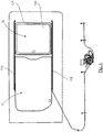
- the figure 1 illustrates a sliding panel flush bay seen from inside the vehicle.
- Such a flush bay is in the form of a set, or shutter device, ready to be placed in a bay (that is to say, an opening, or a hole) formed in the bodywork (side wall by example) or a door, or more generally in the structure of a vehicle (or a caravan or a camper, for example), or more generally a wall to receive a closure device provided with 'an opening.
- Such a closure device comprises a fixed part 11, that is to say remaining immobile relative to the structure that receives it, and a movable panel sliding, or sliding panel, 12, movable relative to the fixed part 11.
- the fixed part 11, also called fixed panel, may in particular be made of glass or polycarbonate, in one or more elements.
- the fixed part 11 is pierced with an opening closed by the movable panel 12 in the position of the figure 1 and extending in the same plane as the fixed part 11.
- This movable panel 12 comprises a glazed portion 122, a frame 121 and a locking / unlocking device.
- Rails respectively an upper rail 114 and a lower rail 115, are attached by gluing on the face of the fixed part 11 facing the inside of the vehicle.
- the rails 114 and 115 which are substantially parallel in this example, hold and slide guide the movable panel 12, which has a frame 121 connected to the rails.
- the movable panel 12 can be moved along the rails 114, 115, in a plane of sliding substantially parallel to the plane defined by the fixed part 11.
- the movable panel 12 can completely close the opening of the fixed part 11 ( figure 1 ) or partially or totally release this opening.
- the movable panel 12 can take one or more open positions, depending on its position relative to the rails 114, 115.
- the movable panel 12 can move perpendicular to the plane defined by the fixed part 11, so as to close the opening, in a closed position ( figure 1 ), in which it is flush with this fixed portion 11, so as to provide a flush assembly (body, fixed part and part mobile).
- the seal may be mounted on the frame 121 of the movable panel 12, in order to come into contact with the fixed part 11.
- the upper rail 114 carries a shuttle (not visible in the figures) and the lower rail 115 carries a shuttle 3 (visible on the figure 2 ), each of the shuttles carrying two grooves located in the vicinity respectively of each lateral edge of the movable panel 12 and cooperating with a front and rear pin secured to an edge of the movable panel.
- Each shuttle 3 is thus slidably guided in a rail 114, 115, along an axis parallel to the axis X, that is to say the axis corresponding to the length of the vehicle.
- the various movements of the movable panel 12 are controlled from means for moving the shuttles 3 inside the guide rails 114, 115.
- the figure 2 illustrates schematically an example of shuttle 3 slidable in a guide rail and having front and rear tracks adapted to cooperate with pins carried by the movable panel.
- a similar shuttle preferably synchronized, is provided in the upper rail 114.
- This shuttle 3 is in the form of a bar of dimensions adapted to slide in the lower rail 115.
- a track, said forward track, or guide groove, 31 controls the displacement of the distal portion of the movable panel 12 (the closest to the front of the vehicle) and a track, said rear track, 32 control the displacement of the proximal portion of the same movable panel 12, opposite to the distal portion.
- the frame 121 of the movable panel 12 carries two upper guide pins (not visible) and two lower guide pins 182 provided to cooperate with a corresponding track respectively formed in the shuttles 3 of the upper rail 114 and the rail lower 115, to control the closing and opening of the movable panel 12, that is to say its displacement in a direction perpendicular to the axis of sliding
- a lower guide pin 182 is thus secured to the distal portion of the movable panel 12 and another lower guide pin 182 is integral with the proximal portion of the movable panel 12, opposite to the distal portion.
- the movement of the shuttles 3 along the guide rails 114, 115 is provided by means of control cables, type "push pull", themselves driven by motorized means controlled by a user.
- the upper and lower shuttles 3 are connected by a cable or foil.
- each of the tracks 31, 32 move the lower pins 182 carried by the movable panel 12 which control the movement of the latter, and in particular the closing and opening of the movable panel.
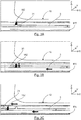
- the Figure 4A illustrates an example of the shape of the front 31 and rear 32 tracks of this lower shuttle 3.
- the front track 31 comprises a rectilinear portion 311, extending parallel to the sliding axis and corresponds to the closed position of the front edge of the movable panel 12. It also comprises an inclined portion 312 forming, with respect to this axis of sliding, an angle ⁇ of the order of 25 °. This inclined portion 312 makes it possible to control the change of position of the front edge of the movable panel 12.
- the rear track 32 also comprises an inclined portion 321 forming, with respect to this sliding axis, an angle ⁇ of the order of 25 °.
- This inclined portion 321 makes it possible to control the change of position of the rear edge of the movable panel. It also comprises a rectilinear portion 322 extending parallel to the axis of sliding.
- the pins 182 carried by the lower edge of the movable panel 12 are, in the closed or closed position of the movable panel 12, abutting the closed end of the rectilinear portion 311 of the front track 31 and abutting the closed end of the inclined portion 321 of the rear track 32.
- the upper shuttle 3 has the same front and rear tracks as the lower shuttle, pins 182 carried by the upper edge of the movable panel 12 cooperating with each of these tracks 31, 32.
- the front 31 and rear 32 tracks are of distinct shapes and symmetrical with respect to a central point located equidistant from the front 31 and rear 32 tracks.
- the lower and upper pawns 182 of the movable panel 12 then move in the front and rear tracks of the lower and upper shuttles.
- the pin 182 cooperating with the front track 31 has moved along the rectilinear portion 311, while the pin 182 cooperating with the rear track 32 has moved in the inclined portion 321 immediately and gradually shifting the rear edge Y of the mobile panel 12 (the same kinematics applying for the upper shuttle).
- the front edge of the movable panel 12 remains in the plane of the fixed panel 11 and therefore does not shift Y, the pin 182 cooperating with the front track 31 moving along the rectilinear portion 311.
- the pins 182 carried by the lower edge of the movable panel 12 are, in the open position of the movable panel, in abutment with the closed end of the inclined portion 312 of the front track 31, as illustrated on FIG. figure 3B , and abutting the closed end of the rectilinear portion 322 of the rear track 32.
- the opening is over.
- the movable panel 12 is in an intermediate position of release, that is to say, it is found in the sliding plane, parallel to the fixed window 11, and opposite the opening in the latter.
- the movable panel 12 slides along the rails 114, 115 to an extreme position called maximum opening.
- the motor and the sliding movable panel 12 can stop in any intermediate sliding position.
- the passage from an open position to the closed position is done symmetrically (from the figure 3C to the figure 3A ).
- the motor moves the shuttles from left to right and once the movable panel 12 located opposite the opening, the front edge of the movable panel 12 shifts Y, then the rear edge.
- the Figure 4B shows the shape of the front 31 and rear 32 tracks of the lower shuttle 3 according to an alternative embodiment.
- the front track 31 comprises an inclined portion 311 forming, with respect to this sliding axis, an angle ⁇ of the order of 25 °.
- This inclined portion 311 controls the change of position of the front edge of the movable panel 12. It also comprises a rectilinear portion 312 extending parallel to the axis of sliding.
- the rear track 32 comprises a rectilinear portion 321, extending parallel to the sliding axis and corresponds to the closed position of the front edge of the movable panel. It also comprises an inclined portion 322 forming, with respect to this sliding axis, an angle ⁇ of the order of 25 °. This inclined portion 322 makes it possible to control the change of position of the rear edge of the movable panel 12.
- the interior of the vehicle can be ventilated by depression when the vehicle is in motion (with an effect similar to the airlocked position of ventilation, called "tilt" in English, of a sunroof).
- the invention thus allows a gradual takeoff of the seal.
- the seal is taken off on one side first of the movable panel 12 to decompress the seal, then on the other side.
- the closed end of the inclined portion 312 of the front track 31 may be slightly offset from that shown in solid lines on the Figure 4A .
- the angle of inclination ⁇ 'of the inclined portion 312 shown in dotted lines is thus equal to 28 ° instead of 25 °.
- the angle of inclination ⁇ 'of the inclined portion 322 of the rear track 32 shown in dashed lines is equal to 28 ° instead of 25 °.
- each shuttle for each guide rail, comprises two fixed pins adapted to cooperate with two grooves carried by an edge of said movable panel.
- the corresponding shuttle for the upper rail, carries two fixed pins adapted to cooperate with two grooves carried by the upper edge of the movable panel.
- the corresponding shuttle for the lower rail, carries two fixed pins adapted to cooperate with two grooves carried by the lower edge of the movable panel.
- the displacement of the movable panel is optimized using synchronization means ensuring the displacement of the upper and lower shuttles synchronously under the action of a single command.
- the invention can also be implemented, of course, in the absence of such synchronization means.
- These synchronization means may for example comprise at least one cable or a foil
- This movement of the shuttles can also be motorized, the electric cable control acting on one of the shuttles which through the synchronization means ensures the movement of the other shuttle.
- the invention can be applied in the same way to other structures having a wall in which is defined a bay, such as, for example, a caravan or a camper.
- the bay may be formed in a side wall of the vehicle (for example for commercial vehicles, minivans, station wagons, ...), in a wall facing the rear of the vehicle (for example for "pick- up "), or in a door.
- the Figure 5A illustrates another example of shape of the front tracks 41 and 42 rear of the lower shuttle 3.
- the Figure 5B illustrates the shape of the front 41 and rear 42 tracks of the upper shuttle 3.
- each track 41, 42 is identical.
- Each track thus comprises a rectilinear portion extending parallel to the sliding axis and a portion inclined with respect to the sliding axis.
- the intermediate position (upper open edge) allows to ventilate the vehicle at a standstill while protecting the interior of the vehicle from light rain.
Abstract
L'invention concerne un dispositif d'obturation d'une baie ménagée dans une structure, comprenant une partie fixe, dans laquelle est définie une ouverture, et au moins un panneau mobile coulissant guidé le long de deux rails de guidage montés sur une face dudit panneau fixe, entre une position d'obturation de ladite ouverture, dans un premier plan défini par ledit panneau fixe, dit plan d'obturation, et au moins une position de coulissement, dans un second plan, dit plan de coulissement, sensiblement parallèle audit plan d'obturation, chacun desdits rails de guidage portant au moins une navette guidée en translation dans ledit rail, chaque navette comprenant deux gorges de guidage ou deux pions fixes aptes à coopérer respectivement avec deux pions fixes ou deux gorges de guidage porté(e)s par ledit panneau mobile, ledit dispositif d'obturation comprenant en outre des moyens d'actionnement agissant sur lesdites navettes pour assurer un déplacement en translation de ces dernières dans lesdits rails de guidage, et le passage du panneau mobile de ladite position d'obturation à ladite au moins une position de coulissement, et réciproquement.The invention relates to a device for closing a bay formed in a structure, comprising a fixed part, in which an opening is defined, and at least one sliding movable panel guided along two guide rails mounted on one face of said fixed panel, between a closed position of said opening, in a first plane defined by said fixed panel, said closed plane, and at least one sliding position, in a second plane, called a sliding plane, substantially parallel to said sealing plane, each of said guide rails carrying at least one shuttle guided in translation in said rail, each shuttle comprising two guide grooves or two fixed pins capable of cooperating respectively with two fixed pins or two guide grooves carried s by said movable panel, said closure device further comprising actuating means acting on said shuttles to ensure a translational movement of the latter eras in said guide rails, and the passage of the movable panel from said closed position to said at least one sliding position, and vice versa.
Description
Le domaine de l'invention est celui de l'équipement des baies, utilisées notamment dans les véhicules automobiles.The field of the invention is that of the equipment of the bays, used in particular in motor vehicles.
Plus précisément, l'invention concerne les dispositifs d'obturation d'une baie ménagée dans un élément de structure, par exemple dans la carrosserie d'un véhicule, ou dans une portière du véhicule, et comprenant une partie mobile coulissante susceptible de libérer ou de fermer une ouverture en offrant un aspect affleurant, vu de l'extérieur.More specifically, the invention relates to devices for closing an array formed in a structural element, for example in the bodywork of a vehicle, or in a door of the vehicle, and comprising a sliding mobile part capable of releasing or to close an opening by offering a flush appearance, seen from the outside.
L'invention peut également équiper d'autres types de structures, tels que les caravanes, les camping-cars, les cars et bus, les minibus, les camions, les camionnettes, les bateaux,...The invention can also equip other types of structures, such as caravans, campers, buses and coaches, minibuses, trucks, vans, boats, ...
De tels dispositifs, développés depuis plusieurs années par le titulaire de la présente demande, sont notamment connus sous le terme "baie flush".Such devices, developed for several years by the holder of the present application, are in particular known by the term "flush bay".
En d'autres termes, ces dispositifs sont conçus de façon à présenter, vu de l'extérieur, un aspect affleurant ou quasi-affleurant entre la carrosserie, ou plus généralement la paroi ou la structure, et le panneau fixe du dispositif.In other words, these devices are designed to have, seen from the outside, a flush or near-flush appearance between the body, or more generally the wall or structure, and the fixed panel of the device.
Le principe de cette technique est notamment décrit dans les documents de brevet
Le dispositif d'obturation (appelé par la suite "baie flush") présenté dans ces documents comprend une partie fixe et une partie mobile par rapport à cette partie fixe, ou panneau coulissant.The shutter device (hereinafter referred to as "flush bay") presented in these documents comprises a fixed part and a moving part with respect to this fixed part, or sliding panel.
La partie mobile est reliée à l'ensemble fixe par des éléments fonctionnels qui assurent la mobilité requise et qui sont rapportés sur la face de la partie fixe tournée vers l'intérieur du véhicule.The movable part is connected to the fixed assembly by functional elements which provide the required mobility and which are reported on the face of the fixed part facing the interior of the vehicle.
Ces éléments fonctionnels, ou rails, assurent une fonction de guidage et de maintien du panneau mobile.These functional elements, or rails, provide a guiding and holding function of the movable panel.
Ils sont placés sur la face orientée vers l'intérieur du véhicule, de façon suffisamment éloignés des bords, ou de la périphérie, de la partie fixe pour que cette périphérie puisse être solidarisée directement aux bords de la baie, sans que les rails n'interfèrent.They are placed on the face facing the interior of the vehicle, sufficiently far from the edges, or the periphery, of the fixed part so that this periphery can be secured directly to the edges of the bay, without the rails n ' interfere.
On peut ainsi s'affranchir de la présence d'un cadre de liaison entre les bords de la baie et la partie fixe.One can thus overcome the presence of a connecting frame between the edges of the bay and the fixed part.
Cette partie fixe peut être réalisée en un ou plusieurs éléments (placés les un à côté des autres dans un même plan), par exemple en verre ou en polycarbonate.This fixed part can be made in one or more elements (placed next to each other in the same plane), for example glass or polycarbonate.
Une telle baie flush peut ainsi être montée intégralement indépendamment du véhicule, et rapportée, depuis l'extérieur, dans le logement défini à cet effet par la baie, ou le logement, définie dans la carrosserie, ou plus généralement dans la paroi.Such a flush bay can thus be mounted integrally independently of the vehicle, and reported from the outside, in the housing defined for this purpose by the bay, or housing, defined in the body, or more generally in the wall.
Les bords de la partie fixe sont solidarisés, par exemple à l'aide d'un cordon de colle, aux bords de la baie, sans autre élément intermédiaire de liaison.The edges of the fixed part are secured, for example by means of a bead of glue, to the edges of the bay, without any other intermediate connecting element.
Sur le plan esthétique, la baie flush présente, vue de l'extérieur, un aspect lisse, affleurant, du fait qu'aucun cadre n'est nécessaire sur le contour de l'ouverture formée dans l'ensemble fixe.From an aesthetic point of view, the flush bay presents, from the outside, a smooth, flush appearance, because no frame is needed on the contour of the opening formed in the fixed assembly.
Pour assurer un coulissement de la partie mobile, constituée généralement par un panneau transparent, on prévoit donc un dispositif de guidage comportant un premier et un second rails de guidage montés fixes sur la partie fixe (ou structure fixe) de la baie, de part et d'autre de l'ouverture fermée par le panneau mobile.To ensure a sliding of the movable part, generally consisting of a transparent panel, there is therefore provided a guiding device comprising a first and a second guide rails fixedly mounted on the fixed part (or fixed structure) of the bay, on both sides. other of the opening closed by the movable panel.
Celui-ci est monté sur les rails, pour coulisser par exemple selon une direction longitudinale, dans un plan de coulissement entre une (ou plusieurs) position d'ouverture et une position de fermeture, dans laquelle il obture l'ouverture.It is mounted on the rails, to slide for example in a longitudinal direction, in a sliding plane between one (or more) open position and a closed position, in which it closes. the opening.
Pour maximiser l'aspect affleurant, il a été proposé que, dans la position de fermeture, le panneau mobile s'inscrive dans le plan de la partie fixe, en passant d'une position intermédiaire de dégagement, dans le plan de coulissement, en regard de l'ouverture et dégagé de celle-ci à la position de fermeture.To maximize the flush appearance, it has been proposed that, in the closed position, the movable panel inscribes itself in the plane of the fixed part, passing from an intermediate position of clearance, in the plane of sliding, to view of the opening and cleared from it in the closed position.
On notera que le terme « plan » doit ici s'entendre dans une acception élargie : le plan formé par la baie est parfois courbe, selon une, voire deux, directions (ceci justifie également, dans certains cas, le terme « sensiblement » utilisé dans la description et les revendications).It should be noted that the term "plan" here must be understood in a broader sense: the plane formed by the bay is sometimes curved, according to one or even two directions (this also justifies, in some cases, the term "substantially" used in the description and claims).
Les baies flush remportent un succès important, dans de nombreuses applications, du fait notamment de la simplicité de leur fabrication et de leur montage, et de l'aspect esthétique qu'elles permettent d'obtenir.Flush racks are an important success in many applications, including the simplicity of their manufacture and assembly, and the aesthetic appearance they can achieve.
Lorsque le panneau mobile est fermé, l'étanchéité entre le panneau mobile et la partie fixe est assurée, classiquement, par un joint d'étanchéité.When the movable panel is closed, the seal between the movable panel and the fixed part is provided, conventionally, by a seal.
Sur les baies actuelles, le panneau mobile se déplace selon un mouvement normal à son plan de forme (en Y pour une vitre latérale), les quatre coins du panneau mobile se déplaçant en même temps.On current bays, the movable panel moves in a normal motion to its plane of form (in Y for a side window), the four corners of the movable panel moving at the same time.
En d'autres termes, le joint d'étanchéité se décolle simultanément sur l'ensemble du bord du panneau mobile (le joint d'étanchéité est décollé en une seule fois)In other words, the seal is peeled off simultaneously over the entire edge of the movable panel (the seal is peeled off at one time)
En cas de gel, le joint d'étanchéité peut rester collé à la vitre fixe ce qui nécessite des efforts excessifs pour ouvrir la vitre portant le joint d'étanchéité.In case of frost, the seal may remain stuck to the fixed window which requires excessive efforts to open the window bearing the seal.
Dans certains cas, il y a un risque de dégradation du joint d'étanchéité ou du mécanisme d'ouverture de la vitre.In some cases, there is a risk of degradation of the seal or the opening mechanism of the window.
L'invention a donc notamment pour objectif de pallier les inconvénients de l'art antérieur cités ci-dessus.The invention therefore particularly aims to overcome the disadvantages of the prior art mentioned above.
Plus précisément, l'invention a pour objectif, dans au moins un mode de réalisation, de fournir un dispositif d'obturation d'une baie qui permette un verrouillage et un déverrouillage, et plus généralement une ouverture et une fermeture, aisés, intuitifs et sans effort important.More specifically, the object of the invention is, in at least one embodiment, to provide a shutter device for a bay that allows locking and unlocking, and more generally an opening and closing, easy, intuitive and without significant effort.
Un autre objectif de l'invention, selon au moins un mode de réalisation, est de fournir un dispositif d'obturation qui évite d'induire des effets néfastes et indésirables entre le panneau mobile et les moyens d'étanchéité associés.Another object of the invention, according to at least one embodiment, is to provide a closure device which avoids inducing adverse and undesirable effects between the movable panel and the associated sealing means.
L'invention a également pour objectif, selon au moins un mode de réalisation, de fournir une nouvelle technique de guidage d'un panneau mobile d'une baie d'obturation d'une structure, telle qu'un véhicule automobile ou similaire, permettant le passage d'une position d'obturation, affleurante avec le panneau fixe à une position de coulissement, qui soit simple, efficace et fiable.The invention also aims, according to at least one embodiment, to provide a new technique for guiding a movable panel of a shutter bay of a structure, such as a motor vehicle or the like, allowing the passage from a closed position, flush with the fixed panel to a sliding position, which is simple, effective and reliable.
Encore un autre objectif de l'invention , selon au moins un mode de réalisation, est de fournir une telle technique qui conserve, autant que faire se peut, tout ou partie des avantages des "baies flush" déjà développées par le titulaire de la présente demande, et notamment :
- aspect esthétique affleurant ;
- aspects aérodynamiques ;
- facilité et coût réduit de fabrication ;
- facilité et coût réduit de montage.
- flush aesthetic appearance;
- aerodynamic aspects;
- ease and reduced cost of manufacture;
- ease and reduced cost of assembly.
Ces objectifs, ainsi que d'autres qui apparaîtront par la suite, sont atteints à l'aide d'un dispositif d'obturation d'une baie ménagée dans une structure, comprenant une partie fixe, dans laquelle est définie une ouverture, et au moins un panneau mobile coulissant guidé le long de deux rails de guidage montés sur une face dudit panneau fixe, entre au moins une position d'obturation de ladite ouverture, dans un premier plan défini par ledit panneau fixe, dit plan d'obturation, et une position de coulissement, dans un second plan, dit plan de coulissement, sensiblement parallèle audit plan d'obturation,
chacun desdits rails de guidage portant au moins une navette guidée en translation dans ledit rail, chaque navette comprenant deux gorges de guidage ou deux pions fixes aptes à coopérer respectivement avec deux pions fixes ou deux gorges de guidage porté(e)s par ledit panneau mobile,
ledit dispositif d'obturation comprenant en outre des moyens d'actionnement agissant sur lesdites navettes pour assurer un déplacement en translation de ces dernières dans lesdits rails de guidage, et le passage du panneau mobile de ladite position d'obturation à ladite position de coulissement, et réciproquement.These objectives, as well as others which will appear later, are achieved by means of a closure device of a bay formed in a structure, comprising a fixed part, in which is defined an opening, and at at least one sliding movable panel guided along two guide rails mounted on one face of said fixed panel, between at least one closed position of said opening, in a first plane defined by said fixed panel, said shutter plane, and a sliding position, in a second plane, said sliding plane, substantially parallel to said shutter plane,
each of said guide rails carrying at least one shuttle guided in translation in said rail, each shuttle comprising two guide grooves or two fixed pins adapted to cooperate respectively with two fixed pins or two guide grooves carried by said movable panel ,
said closure device further comprising actuating means acting on said shuttles to ensure a translational movement of the latter in said guide rails, and the passage of the movable panel from said closed position to said sliding position, and reciprocally.
Selon l'invention, pour chacune des rails de guidage, les deux gorges de guidage des pions du panneau mobile ou de la navette sont de formes distinctes de façon à assurer, lorsque les navettes sont déplacées dans lesdits rails à partir de la position d'obturation, le déplacement transversal par rapport auxdits rails d'une première partie du panneau mobile, puis le déplacement transversal par rapport auxdits rails de l'autre partie du panneau mobile, permettant le passage du panneau mobile dans une position intermédiaire de dégagement, dans le plan de coulissement, en regard de l'ouverture et dégagé de celle-ci.According to the invention, for each of the guide rails, the two guide grooves of the pions of the movable panel or the shuttle are of distinct shapes so as to ensure, when the shuttles are moved in said rails from the position of shutting, the transverse displacement relative to said rails of a first portion of the movable panel, then the transverse displacement relative to said rails of the other part of the movable panel, allowing the passage of the movable panel in an intermediate position of disengagement, in the sliding plane, facing the opening and cleared thereof.
Le trajet des pions de guidage du panneau mobile dans les deux gorges de guidage de chacune des navettes est différent.The path of the guide pins of the movable panel in the two guide grooves of each of the shuttles is different.
On obtient ainsi un décalage du panneau mobile du plan d'obturation vers le plan de coulissement en deux temps, et par conséquent un décollage progressif (et non pas en une seule fois) du joint d'étanchéité porté par la partie fixe ou le panneau mobile, notamment en cas de gel.This results in a shift of the movable panel from the shutter plane to the sliding plane in two stages, and consequently a gradual (and not all at once) take-off of the seal carried by the fixed part or the panel. mobile, especially in case of frost.
On minimise ainsi les risques de dégradation du joint d'étanchéité ou du mécanisme d'ouverture du panneau mobile.This minimizes the risk of degradation of the seal or the opening mechanism of the movable panel.
Selon un aspect particulier de l'invention, pour chacun des rails de guidage, une première gorge de guidage d'une navette ou du panneau mobile présente une première portion inclinée par rapport au plan de coulissement, permettant à partir de la position d'obturation le déplacement transversal par rapport auxdits rails d'une première partie du panneau mobile et une seconde portion s'étendant sensiblement parallèlement audit plan de coulissement, la deuxième gorge de guidage de ladite navette ou du panneau mobile présentant une première portion s'étendant sensiblement parallèlement audit plan de coulissement et une deuxième portion inclinée par rapport au plan de coulissement, permettant le déplacement transversal par rapport auxdits rails de l'autre partie du panneau mobile, permettant le passage du panneau mobile dans la position de coulissement.According to a particular aspect of the invention, for each of the guide rails, a first guide groove of a shuttle or of the movable panel has a first portion inclined with respect to the sliding plane, allowing from the closed position the transverse displacement relative to said rails of a first portion of the movable panel and a second portion extending substantially parallel to said sliding plane, the second guide groove of said shuttle or the movable panel having a first portion extending substantially in parallel said sliding plane and a second portion inclined with respect to the sliding plane, allowing the transverse displacement relative to said rails of the other part of the movable panel, allowing the passage of the movable panel in the sliding position.
Les deux gorges de guidage formées dans chacune des navettes des rails supérieur et inférieur sont configurées de sorte à déplacer la partie avant puis la partie arrière du panneau mobile de la position d'obturation vers la position de coulissement, dans le but d'agir progressivement sur le joint d'étanchéité, notamment en cas de gel.The two guide grooves formed in each of the shuttles of the upper and lower rails are configured so as to move the front part and the rear part of the movable panel from the closed position to the sliding position, in order to act progressively. on the seal, especially in case of frost.
Selon un aspect particulier de l'invention, les première et deuxième gorges de guidage d'une navette ou du panneau mobile sont symétriques par rapport à un point central situé à égale distance des deux gorges.According to a particular aspect of the invention, the first and second guide grooves of a shuttle or the movable panel are symmetrical with respect to a central point equidistant from the two grooves.
Selon un aspect particulier de l'invention, l'inclinaison de la deuxième portion inclinée de la deuxième gorge par rapport au plan de coulissement est supérieure à l'inclinaison de la première portion inclinée de la première gorge par rapport au plan de coulissement.According to a particular aspect of the invention, the inclination of the second inclined portion of the second groove relative to the sliding plane is greater than the inclination of the first inclined portion of the first groove relative to the sliding plane.
La différence d'inclinaison est, par exemple, comprise entre 1 et 5°.The inclination difference is, for example, between 1 and 5 °.
Ce décalage permet de bloquer le panneau mobile en position ouverte de sorte à limiter les vibrations.This offset makes it possible to block the movable panel in the open position so as to limit the vibrations.
Selon un aspect particulier de l'invention, le dispositif d'obturation comprend des moyens de synchronisation, reliant les deux navettes équipant respectivement les deux rails, de façon que les deux navettes soient actionnées simultanément.According to a particular aspect of the invention, the shutter device comprises synchronization means, connecting the two shuttles equipping respectively the two rails, so that the two shuttles are operated simultaneously.
Selon un aspect particulier de l'invention, lesdits moyens de synchronisation comprennent au moins un câble ou un clinquant.According to a particular aspect of the invention, said synchronization means comprise at least one cable or foil.
Selon une mise en oeuvre particulière de l'invention, la partie fixe est muni de moyens d'étanchéité destinés à être placés en contact avec une périphérie dudit panneau mobile dans ladite position d'obturation.According to a particular embodiment of the invention, the fixed part is provided with sealing means intended to be placed in contact with a periphery of said movable panel in said closed position.
Selon une autre mise en oeuvre particulière de l'invention, le panneau mobile est muni de moyens d'étanchéité destinés à être placés en contact avec une périphérie de l'ouverture de la partie fixe dans ladite position d'obturation.According to another particular embodiment of the invention, the movable panel is provided with sealing means intended to be placed in contact with a periphery of the opening of the fixed part in said closed position.
Selon un aspect particulier de l'invention, le dispositif d'obturation est monté sur une portière ou une portion latérale de carrosserie.According to one particular aspect of the invention, the shutter device is mounted on a door or a lateral portion of the bodywork.
L'invention concerne également les véhicules automobiles comprenant au moins un dispositif d'obturation tel que décrit ci-dessus.The invention also relates to motor vehicles comprising at least one closure device as described above.
Ce dispositif peut notamment être monté sur une paroi latérale du véhicule ou une portière, ou former tout ou partie d'un pavillon.This device may in particular be mounted on a side wall of the vehicle or a door, or form all or part of a roof.
Le terme « véhicule » automobile s'entend ici dans un sens large, et englobe notamment les camions, les camionnettes, cars, camping-cars,...The term "vehicle" automobile means here in a broad sense, and includes including trucks, vans, buses, motor homes, ...
Un tel dispositif d'obturation peut également être adapté sur d'autres structures présentant des contraintes similaires, telles que les caravanes, les « mobile homes », les bateaux,...Such a closure device can also be adapted to other structures with similar constraints, such as caravans, mobile homes, boats, etc.
L'invention, ainsi que les différents avantages qu'elle présente, seront plus facilement compris grâce à la description qui va suivre, donnée à titre simplement illustratif et non limitatif en référence aux
- la
figure 1 illustre un mode de réalisation d'un dispositif d'obturation, ou baie flush, selon l'invention ; - la
figure 2 est une vue partielle d'un dispositif d'obturation conforme à l'invention, montrant un exemple de navette apte à coulisser dans un rail de guidage et présentant des pistes avant et arrière aptes à coopérer avec des pions portés par le panneau mobile ; - les
figures 3A à 3C sont des vues de détail d'une navette se déplaçant dans un rail de guidage entre une position d'obturation du panneau mobile et une position de coulissement ; - la
figure 4A illustre un premier exemple de pistes avant (à gauche) et arrière (à droite) d'une navette mise en oeuvre dans un dispositif d'obturation conforme à l'invention; - la
figure 4B illustre un deuxième exemple de pistes avant (à gauche) et arrière (à droite) d'une navette mise en oeuvre dispositif d'obturation conforme à l'invention, et - les
figures 5A et 5B illustrent un autre exemple de forme des pistes avant et arrière de la navette inférieure (figure 5A ) et de la navette supérieure (figure 5B ).
- the
figure 1 illustrates an embodiment of a shutter device, or flush bay, according to the invention; - the
figure 2 is a partial view of a closure device according to the invention, showing an example of shuttle slidable in a guide rail and having front and rear tracks adapted to cooperate with pins carried by the movable panel; - the
FIGS. 3A to 3C are detail views of a shuttle moving in a guide rail between a shutter position of the movable panel and a sliding position; - the
Figure 4A illustrates a first example of tracks before (left) and back (right) of a shuttle implemented in a closure device according to the invention; - the
Figure 4B illustrates a second example of front (left) and rear (right) tracks of a shutter implemented shutter according to the invention, and - the
Figures 5A and 5B illustrate another example of shape of the front and rear tracks of the lower shuttle (Figure 5A ) and the upper shuttle (Figure 5B ).
La
Une telle baie flush se présente sous la forme d'un ensemble, ou dispositif d'obturation, prêt à être placé dans une baie (c'est-à-dire une ouverture, ou un trou) ménagée dans la carrosserie (paroi latérale par exemple) ou une porte, ou plus généralement dans la structure d'un véhicule (ou d'une caravane ou d'un camping-car, par exemple), ou plus généralement d'une paroi devant recevoir un dispositif d'obturation muni d'un ouvrant.Such a flush bay is in the form of a set, or shutter device, ready to be placed in a bay (that is to say, an opening, or a hole) formed in the bodywork (side wall by example) or a door, or more generally in the structure of a vehicle (or a caravan or a camper, for example), or more generally a wall to receive a closure device provided with 'an opening.
Un tel dispositif d'obturation comprend une partie fixe 11, c'est-à-dire restant immobile par rapport à la structure qui la reçoit, et un panneau mobile en coulissement, ou panneau coulissant, 12, mobile par rapport à la partie fixe 11.Such a closure device comprises a
La partie fixe 11, encore appelée panneau fixe, peut notamment être réalisée en verre ou en polycarbonate, en un ou plusieurs éléments.The
La partie fixe 11 est percée d'une ouverture obturée par le panneau mobile 12 dans la position de la
Ce panneau mobile 12 comporte une portion vitrée 122, un cadre 121 et un dispositif de verrouillage / déverrouillage.This
Des rails, respectivement un rail supérieur 114 et un rail inférieur 115, sont rapportés par collage sur la face de la partie fixe 11 orientée vers l'intérieur du véhicule.Rails, respectively an
On note que ces rails sont éloignés du contour de la partie fixe, et ne participent pas ni ne nuisent à la solidarisation de celle-ci au bord de la baie.Note that these rails are far from the contour of the fixed part, and do not participate in or interfere with the joining of the latter to the edge of the bay.
Les rails 114 et 115, qui sont sensiblement parallèle dans cet exemple, maintiennent et guident en coulissement le panneau mobile 12, qui présente un cadre 121 relié aux rails.The
Le panneau mobile 12 peut être déplacé le long des rails 114, 115, dans un plan de coulissement sensiblement parallèle au plan défini par la partie fixe 11.The
Le panneau mobile 12 peut venir obturer complètement l'ouverture de la partie fixe 11 (
Ainsi, le panneau mobile 12 peut prendre une ou plusieurs positions d'ouverture, selon sa position par rapport aux rails 114, 115.Thus, the
Par ailleurs, le panneau mobile 12 peut se déplacer perpendiculairement au plan défini par la partie fixe 11, de façon à venir obturer l'ouverture, dans une position fermée (
La face de la partie fixe 11 tournée vers l'intérieur du véhicule porte par ailleurs un joint d'étanchéité (non représenté sur la
Dans une variante, le joint d'étanchéité peut être monté sur le cadre 121 du panneau mobile 12, pour venir en contact avec la partie fixe 11.In a variant, the seal may be mounted on the
Dans ce mode de réalisation, le rail supérieur 114 porte une navette (non visible sur les figures) et le rail inférieur 115 porte une navette 3 (visible sur la
Chaque navette 3 est ainsi guidée en coulissement dans un rail 114, 115, selon un axe parallèle à l'axe X, c'est-à-dire l'axe correspondant à la longueur du véhicule.Each
Les différents mouvements du panneau mobile 12 sont contrôlés à partir de moyens de mise en mouvement des navettes 3 à l'intérieur des rails de guidage 114, 115.The various movements of the
La
Elle est destinée à se déplacer dans le rail inférieur 115. Une navette similaire, de préférence synchronisée, est prévue dans le rail supérieur 114.It is intended to move in the
Cette navette 3 se présente sous la forme d'un barreau de dimensions adaptées pour coulisser dans le rail inférieur 115.This
Pour chaque navette 3, une piste, dite piste avant, ou gorge de guidage, 31 contrôle le déplacement de la partie distale du panneau mobile 12 (la plus proche de l'avant du véhicule) et une piste, dite piste arrière, 32 contrôle le déplacement de la partie proximale de ce même panneau mobile 12, opposée à la partie distale.For each
Dans l'exemple illustré, le cadre 121 du panneau mobile 12 porte deux pions de guidage supérieurs (non visibles) et deux pions de guidage inférieurs 182 prévus pour coopérer avec une piste correspondante formée respectivement dans les navettes 3 du rail supérieur 114 et du rail inférieur 115, pour contrôler la fermeture et l'ouverture du panneau mobile 12, c'est-à-dire son déplacement dans une direction perpendiculaire à l'axe de coulissementIn the example shown, the
Un pion 182 de guidage inférieur est ainsi solidaire de la partie distale du panneau mobile 12 et un autre pion 182 de guidage inférieur est solidaire de la partie proximale du panneau mobile 12, opposée à la partie distale.A
Le mouvement des navettes 3 le long des rails de guidage 114, 115 est assuré par le biais de câbles de commande, de type "push pull", eux même entrainés par des moyens motorisés commandés par un utilisateur.The movement of the
Les navettes 3 supérieure et inférieure sont reliées par un câble ou clinquant.The upper and
Comme illustré sur la
Le mouvement du panneau mobile 12 par rapport à la partie fixe 11 peut se décomposer en deux déplacements indépendants :
- un déplacement perpendiculaire vers l'intérieur du véhicule en deux temps par rapport au plan formé par la partie fixe 11, permettant le passage d'une position fermée et verrouillée, dans laquelle le panneau mobile 12 se trouve dans le même plan que la partie fixe 11 et l'ouverture, à une position intermédiaire de dégagement, dans laquelle le panneau mobile 12 est décalé par rapport à la partie fixe 11 en regard de l'ouverture et dégagé de celle-ci, dans un plan de coulissement, de façon à permettre ce coulissement - le panneau mobile 12 est ainsi mobile selon une direction de déverrouillage perpendiculaire à la direction de coulissement;
- un déplacement dans le plan de coulissement, parallèle au plan formé par la partie fixe 11.
- a perpendicular displacement towards the inside of the vehicle in two stages relative to the plane formed by the fixed
part 11, allowing the passage of a closed and locked position, in which themovable panel 12 is in the same plane as thefixed part 11 and the opening, at an intermediate position of clearance, in which themovable panel 12 is offset relative to the fixedpart 11 opposite the opening and cleared from it, in a sliding plane, so as to allow this sliding - themovable panel 12 is thus movable in an unlocking direction perpendicular to the sliding direction; - a displacement in the plane of sliding, parallel to the plane formed by the fixed
part 11.
La
La piste avant 31 comprend une portion rectiligne 311, s'étendant parallèlement à l'axe de coulissement et correspond à la position d'obturation du bord avant du panneau mobile 12. Elle comprend également une portion inclinée 312 formant, par rapport à cet axe de coulissement, un angle α de l'ordre de 25°. Cette portion inclinée 312 permet de contrôler le changement de position du bord avant du panneau mobile 12.The
La piste arrière 32 comprend également une portion inclinée 321 formant, par rapport à cet axe de coulissement, un angle α de l'ordre de 25°. Cette portion inclinée 321 permet de contrôler le changement de position du bord arrière du panneau mobile. Elle comprend également une portion rectiligne 322 s'étendant parallèlement à l'axe de coulissement.The
Les pions 182 portés par le bord inférieur du panneau mobile 12 sont, dans la position d'obturation ou fermée du panneau mobile 12, en butée à l'extrémité fermée de la portion rectiligne 311 de la piste avant 31 et en butée à l'extrémité fermée de la portion inclinée 321 de la piste arrière 32.The
La navette 3 supérieure présente les mêmes pistes avant et arrière que la navette inférieure, des pions 182 portés par le bord supérieur du panneau mobile 12 coopérant avec chacune de ces pistes 31, 32.The
Ainsi, quatre pistes au total sont mises en oeuvre dans les navettes (et non pas dans les rails), dont deux pistes avant et deux pistes arrière.Thus, four tracks in total are implemented in the shuttles (and not in the rails), including two front tracks and two rear tracks.
Pour chacune des navettes 3 supérieure et inférieure, les pistes avant 31 et arrière 32 sont de formes distinctes et symétriques par rapport à un point central situé à égale distance des pistes avant 31 et arrière 32.For each of the upper and
A partir de la position fermée du panneau mobile 12, le moteur tire le câble et les navettes 3 inférieure et supérieure.From the closed position of the
Les pions 182 inférieur et supérieur du panneau mobile 12 se déplacent alors dans les pistes avant et arrière des navettes inférieure et supérieure.The lower and
Sur la
Le pion 182 coopérant avec la piste avant 31 s'est déplacé le long de la portion rectiligne 311, alors que le pion 182 coopérant avec la piste arrière 32 s'est déplacé dans la portion inclinée 321 décalant immédiatement et progressivement en Y le bord arrière du panneau mobile 12 (la même cinématique s'appliquant pour la navette supérieure). Le bord avant du panneau mobile 12 reste dans le plan du panneau fixe 11 et ne se décale donc pas en Y, le pion 182 coopérant avec la piste avant 31 se déplaçant le long de la portion rectiligne 311.The
On peut par une consigne électronique arrêter le moteur (et donc le déplacement des navettes 3 inférieure et supérieure) dans cette position intermédiaire. Lorsque le moteur continue de tirer les navettes 3 inférieure et supérieure, le pion 182 coopérant avec la piste avant 31 se déplace dans la portion inclinée 312 décalant alors le bord avant du panneau mobile 12, le pion 182 coopérant avec la piste arrière 32 se déplaçant dans la portion rectiligne 322.It is possible by an electronic command to stop the engine (and therefore the movement of the 3 and lower shuttles 3) in this intermediate position. When the engine continues to pull the lower and
C'est donc le bord arrière du panneau mobile 12 qui se décale d'abord en Y, puis le bord avant.It is therefore the rear edge of the
Les pions 182 portés par le bord inférieur du panneau mobile 12 sont, dans la position ouverte du panneau mobile, en butée à l'extrémité fermée de la portion inclinée 312 de la piste avant 31, comme illustré sur la
Sur la
Une fois l'ensemble du panneau mobile 12 décalé en Y, le déplacement de la navette 3 de la droite vers la gauche entraîne le coulissement en X du panneau mobile 12, dans le plan de coulissement, de la droite vers la gauche.Once the entire
Le panneau mobile 12 coulisse le long des rails 114, 115 jusqu'à une position extrême dite d'ouverture maximale.The
Par une consigne électronique, le moteur et le panneau mobile 12 coulissant peuvent s'arrêter dans une position intermédiaire de coulissement quelconque.By an electronic setpoint, the motor and the sliding
Le passage d'une position ouverte à la position d'obturation se fait de façon symétrique (de la
D'autres angles, et le cas échéant des formes légèrement différentes, par exemple incurvées, peuvent être envisagées pour les pistes 31, 32.Other angles, and possibly slightly different shapes, for example curved, can be envisaged for the
La
La piste avant 31 comprend une portion inclinée 311 formant, par rapport à cet axe de coulissement, un angle α de l'ordre de 25°. Cette portion inclinée 311 permet de contrôler le changement de position du bord avant du panneau mobile 12. Elle comprend également une portion rectiligne 312 s'étendant parallèlement à l'axe de coulissement.The
La piste arrière 32 comprend une portion rectiligne 321, s'étendant parallèlement à l'axe de coulissement et correspond à la position d'obturation du bord avant du panneau mobile. Elle comprend également une portion inclinée 322 formant, par rapport à cet axe de coulissement, un angle α de l'ordre de 25°. Cette portion inclinée 322 permet de contrôler le changement de position du bord arrière du panneau mobile 12.The
C'est donc le bord avant du panneau mobile 12 qui se décale en Y, puis le bord arrière à partir de la position d'obturation du panneau mobile 12.It is therefore the front edge of the
Lorsque seule la partie avant du panneau mobile 12 est ouverte, l'intérieur du véhicule peut être aéré par dépression lorsque le véhicule est en mouvement (avec un effet similaire à la position entrebâillée de ventilation, dite "tilt" en anglais, d'un toit ouvrant).When only the front portion of the
L'invention permet ainsi un décollage progressif du joint d'étanchéité.The invention thus allows a gradual takeoff of the seal.
Pour ce faire, on ouvre d'abord la moitié avant ou arrière du panneau mobile 12, puis l'autre moitié. En d'autres termes, on décale le panneau mobile 12 en deux temps.To do this, first open the front half or rear of the
On répartit de la sorte les efforts sur une zone plus petite du joint d'étanchéité.This distributes the forces in a smaller area of the seal.
En cas de gel, on décolle le joint d'étanchéité sur un côté d'abord du panneau mobile 12 pour décomprimer le joint, puis sur l'autre côté.In case of frost, the seal is taken off on one side first of the
Selon une mise en oeuvre particulière de l'invention, l'extrémité fermée de la portion inclinée 312 de la piste avant 31 peut être légèrement décalée par rapport à celle illustrée en traits pleins sur la
Dans l'exemple de la
Cette légère déformation permet d'introduire un frottement ou une contrainte en fin d'ouverture du panneau mobile 12 de sorte à caler/bloquer ce dernier et éviter les vibrations et bruits (sans ajout de pièce donc économique).This slight deformation makes it possible to introduce a friction or a constraint at the end of opening of the
Dans un autre mode de réalisation, pour chaque rail de guidage, chaque navette comprend deux pions fixes aptes à coopérer avec deux gorges portées par un bord dudit panneau mobile.In another embodiment, for each guide rail, each shuttle comprises two fixed pins adapted to cooperate with two grooves carried by an edge of said movable panel.
Ainsi, pour le rail supérieur, la navette correspondante porte deux pions fixes aptes à coopérer avec deux gorges portées par le bord supérieur du panneau mobile. Pour le rail inférieur, la navette correspondante porte deux pions fixes aptes à coopérer avec deux gorges portées par le bord inférieur du panneau mobile.Thus, for the upper rail, the corresponding shuttle carries two fixed pins adapted to cooperate with two grooves carried by the upper edge of the movable panel. For the lower rail, the corresponding shuttle carries two fixed pins adapted to cooperate with two grooves carried by the lower edge of the movable panel.
Préférentiellement, le déplacement du panneau mobile est optimisé à l'aide de moyens de synchronisation assurant le déplacement des navettes supérieure et inférieure de façon synchronisée sous l'action d'une commande unique.Preferably, the displacement of the movable panel is optimized using synchronization means ensuring the displacement of the upper and lower shuttles synchronously under the action of a single command.
L'invention peut également être mise en oeuvre, bien sur, en l'absence de tels moyens de synchronisation.The invention can also be implemented, of course, in the absence of such synchronization means.
Ces moyens de synchronisation peuvent par exemple comprendre au moins un câble ou un clinquantThese synchronization means may for example comprise at least one cable or a foil
Pour ouvrir le panneau mobile, on peut agir manuellement, par le biais d'une poignée par exemple, sur les moyens de synchronisation des deux navettes.To open the movable panel, it is possible to act manually, by means of a handle for example, on the means of synchronization of the two shuttles.
Ce déplacement des navettes peut également être motorisé, la commande électrique par câble agissant sur une des navettes qui par le biais des moyens de synchronisation assure le déplacement de l'autre navette.This movement of the shuttles can also be motorized, the electric cable control acting on one of the shuttles which through the synchronization means ensures the movement of the other shuttle.
Les modes de réalisation décrits ci-dessus s'appliquent à une paroi latérale d'un véhicule automobile.The embodiments described above apply to a side wall of a motor vehicle.
L'invention peut s'appliquer de la même façon à d'autres structures présentant une paroi dans laquelle est définie une baie, comme, par exemple, une caravane ou un camping-car.The invention can be applied in the same way to other structures having a wall in which is defined a bay, such as, for example, a caravan or a camper.
Notamment, la baie peut être formée dans une paroi latérale du véhicule (par exemple pour les véhicules utilitaires, les monospaces, les breaks,...), dans une paroi orientée vers l'arrière du véhicule (par exemple pour les « pick-up »), ou encore dans une portière.In particular, the bay may be formed in a side wall of the vehicle (for example for commercial vehicles, minivans, station wagons, ...), in a wall facing the rear of the vehicle (for example for "pick- up "), or in a door.
Il peut également s'agir d'une baie de séparation d'un véhicule.It can also be a separation bay of a vehicle.
La
La
Dans cet exemple des
Dans ce cas de figure, c'est le bord supérieur du panneau mobile 12 qui se décale d'abord en Y, puis le bord inférieur.In this case, it is the upper edge of the
La position intermédiaire (bord supérieur ouvert) permet d'aérer le véhicule à l'arrêt tout en protégeant l'intérieur du véhicule d'une légère pluie.The intermediate position (upper open edge) allows to ventilate the vehicle at a standstill while protecting the interior of the vehicle from light rain.
Claims (9)
chacun desdits rails de guidage portant au moins une navette guidée en translation dans ledit rail, chaque navette comprenant deux gorges de guidage ou deux pions fixes aptes à coopérer respectivement avec deux pions fixes ou deux gorges de guidage porté(e)s par ledit panneau mobile,
ledit dispositif d'obturation comprenant en outre des moyens d'actionnement agissant sur lesdites navettes pour assurer un déplacement en translation de ces dernières dans lesdits rails de guidage, et le passage du panneau mobile de ladite position d'obturation à ladite au moins une position de coulissement, et réciproquement,
ledit dispositif d'obturation étant caractérisé en ce que, pour chacun desdits rails de guidage, les deux gorges de guidage des pions du panneau mobile ou de la navette sont de formes distinctes de façon à assurer, lorsque les navettes sont déplacées dans lesdits rails à partir de la position d'obturation, le déplacement transversal par rapport auxdits rails d'une première partie du panneau mobile, puis le déplacement transversal par rapport auxdits rails de l'autre partie du panneau mobile, permettant le passage du panneau mobile dans une position intermédiaire de dégagement, dans le plan de coulissement, en regard de l'ouverture et dégagé de celle-ci.Device for closing an array formed in a structure, comprising a fixed part, in which an opening is defined, and at least one sliding movable panel guided along two guide rails mounted on one face of said fixed panel, between a shutter position of said aperture, in a first plane defined by said fixed panel, said shutter plane, and at least one sliding position, in a second plane, said sliding plane, substantially parallel to said shutter plane,
each of said guide rails carrying at least one shuttle guided in translation in said rail, each shuttle comprising two guide grooves or two fixed pins adapted to cooperate respectively with two fixed pins or two guide grooves carried by said movable panel ,
said closure device further comprising actuating means acting on said shuttles to ensure a translational movement of the latter in said guide rails, and the passage of the movable panel from said closed position to said at least one position sliding, and vice versa,
said closure device being characterized in that , for each of said guide rails, the two guide grooves of the pions of the movable panel or the shuttle are of distinct shapes so as to ensure, when the shuttles are moved in said rails to from the shutter position, the transverse displacement relative to said rails of a first portion of the movable panel, then the transverse displacement relative to said rails of the other part of the movable panel, allowing the passage of the movable panel in a position intermediate release, in the sliding plane, facing the opening and cleared thereof.
Priority Applications (1)
| Application Number | Priority Date | Filing Date | Title |
|---|---|---|---|
| EP18169047.0A EP3560741B1 (en) | 2018-04-24 | 2018-04-24 | Device for sealing an opening made in the body of a vehicle, and corresponding vehicle |
Applications Claiming Priority (1)
| Application Number | Priority Date | Filing Date | Title |
|---|---|---|---|
| EP18169047.0A EP3560741B1 (en) | 2018-04-24 | 2018-04-24 | Device for sealing an opening made in the body of a vehicle, and corresponding vehicle |
Publications (2)
| Publication Number | Publication Date |
|---|---|
| EP3560741A1 true EP3560741A1 (en) | 2019-10-30 |
| EP3560741B1 EP3560741B1 (en) | 2020-09-30 |
Family
ID=62062933
Family Applications (1)
| Application Number | Title | Priority Date | Filing Date |
|---|---|---|---|
| EP18169047.0A Active EP3560741B1 (en) | 2018-04-24 | 2018-04-24 | Device for sealing an opening made in the body of a vehicle, and corresponding vehicle |
Country Status (1)
| Country | Link |
|---|---|
| EP (1) | EP3560741B1 (en) |
Citations (6)
| Publication number | Priority date | Publication date | Assignee | Title |
|---|---|---|---|---|
| EP0778168A1 (en) | 1995-12-08 | 1997-06-11 | FARNIER & PENIN SNC | Closing device, flush mounted on a vehicle opening |
| EP0857844A1 (en) | 1997-02-10 | 1998-08-12 | Wagon Automotive | Guiding device for a sliding and swaying wing closing an opening |
| FR2833213A1 (en) * | 2001-12-10 | 2003-06-13 | Wagon Automotive Snc | Opening/closing system e.g. for window in motor vehicle door has mobile component mounted on single support/guide providing two-stage movement |
| FR2924739A1 (en) * | 2007-12-10 | 2009-06-12 | Wagon Sas | DEVICE FOR SEALING A BAY MADE IN THE BODYWORK OF A VEHICLE, WITH A GUIDE ELEMENT AND SLIDING SLIDER AND VEHICLE THEREFOR |
| FR2963282A1 (en) * | 2010-07-30 | 2012-02-03 | Acs France Sas | Device for closing opening i.e. window, formed in body of roof of motor vehicle such as car, has movable panel assembled on movable frame that is provided with tilting unit to tilt movable panel with respect to movable frame |
| EP2479366A2 (en) * | 2011-01-19 | 2012-07-25 | Advanced Comfort Systems France SAS - ACS France | Device for closing an opening in a vehicle and vehicle which corresponds |
-
2018
- 2018-04-24 EP EP18169047.0A patent/EP3560741B1/en active Active
Patent Citations (6)
| Publication number | Priority date | Publication date | Assignee | Title |
|---|---|---|---|---|
| EP0778168A1 (en) | 1995-12-08 | 1997-06-11 | FARNIER & PENIN SNC | Closing device, flush mounted on a vehicle opening |
| EP0857844A1 (en) | 1997-02-10 | 1998-08-12 | Wagon Automotive | Guiding device for a sliding and swaying wing closing an opening |
| FR2833213A1 (en) * | 2001-12-10 | 2003-06-13 | Wagon Automotive Snc | Opening/closing system e.g. for window in motor vehicle door has mobile component mounted on single support/guide providing two-stage movement |
| FR2924739A1 (en) * | 2007-12-10 | 2009-06-12 | Wagon Sas | DEVICE FOR SEALING A BAY MADE IN THE BODYWORK OF A VEHICLE, WITH A GUIDE ELEMENT AND SLIDING SLIDER AND VEHICLE THEREFOR |
| FR2963282A1 (en) * | 2010-07-30 | 2012-02-03 | Acs France Sas | Device for closing opening i.e. window, formed in body of roof of motor vehicle such as car, has movable panel assembled on movable frame that is provided with tilting unit to tilt movable panel with respect to movable frame |
| EP2479366A2 (en) * | 2011-01-19 | 2012-07-25 | Advanced Comfort Systems France SAS - ACS France | Device for closing an opening in a vehicle and vehicle which corresponds |
Also Published As
| Publication number | Publication date |
|---|---|
| EP3560741B1 (en) | 2020-09-30 |
Similar Documents
| Publication | Publication Date | Title |
|---|---|---|
| EP2442993B1 (en) | Device for closing an opening made in the body of an automobile including a synchronisation means, and corresponding automobile | |
| EP0857844B1 (en) | Guiding device for a sliding and swaying wing closing an opening | |
| FR2924739A1 (en) | DEVICE FOR SEALING A BAY MADE IN THE BODYWORK OF A VEHICLE, WITH A GUIDE ELEMENT AND SLIDING SLIDER AND VEHICLE THEREFOR | |
| EP2479366B1 (en) | Device for closing an opening in a vehicle | |
| EP1939384B1 (en) | Device for locking an opening made in the body of a vehicle with a mobile pin forming a bolt, and corresponding vehicle | |
| FR3021254A1 (en) | FLASHING WINDOW DEVICE FOR MOTOR VEHICLE DOOR WITH ADJUSTABLE MOBILE PANEL, DOOR AND MOTOR VEHICLE CORRESPONDING THERETO. | |
| EP3967531B1 (en) | Device for sealing an opening made in the body of a vehicle, and corresponding vehicle | |
| EP3560741B1 (en) | Device for sealing an opening made in the body of a vehicle, and corresponding vehicle | |
| FR2833209A1 (en) | Sealing device for automobile bodywork recess comprises panel carried by sliding elements guided by grooves in rail | |
| FR2833212A1 (en) | Closer for aperture in vehicle body, e.g. sliding window in door has mobile component mounted on support/guide providing two movements | |
| EP1433633B1 (en) | Closing device of an opening in a vehicle and corresponding vehicle | |
| EP1323557B1 (en) | Closing device for an opening in a vehicle with a mobile rotatory pane and corresponding vehicle | |
| EP4223568A1 (en) | Device for sealing an opening made in the body of a vehicle, and corresponding vehicle | |
| EP1323558B1 (en) | Powered closing unit of an opening of a vehicle and corresponding vehicle | |
| EP2263895B1 (en) | Device for closing an opening in the body of an automobile including balancing means and automobile with such a device | |
| WO2023147865A1 (en) | Device for closing off an opening made in the body of a vehicle, and corresponding vehicle | |
| EP2089245B1 (en) | Tailgate structure for an automotive vehicle and automotive vehicle with such structure | |
| FR2833213A1 (en) | Opening/closing system e.g. for window in motor vehicle door has mobile component mounted on single support/guide providing two-stage movement | |
| EP4124484A1 (en) | Device for sealing an opening made in the body of a vehicle, and corresponding vehicle | |
| EP2457756B1 (en) | Glazed pavilion with tilting and sliding mobile panel | |
| FR2983129A1 (en) | Glazed roof for car, has mobile panel guided by two guide rails, where portion of mobile panel is arranged close to distal end, and another portion of mobile panel is arranged close to stationary proximal end | |
| FR2881687A1 (en) | Roof`s glazed surface occultation device for motor vehicle, has intermediate shutter with gutter cooperating with slider sliding in rail to displace intermediate shutter, where front, rear and intermediate shutter are connected by abutments | |
| EP1598513A1 (en) | Vehicle door with sliding window panel. | |
| FR2546955A1 (en) | Panel arrangement, especially door or window, of the lift-and-slide type and use of such an arrangement for cabs of vehicles, such as tractors or the like | |
| FR2934972A1 (en) | Passenger compartment structure retracting method for e.g. two-door saloon, involves pivoting structure simultaneously with movement of structure towards back of vehicle, while maintaining panel on window, to insert structure in boot |
Legal Events
| Date | Code | Title | Description |
|---|---|---|---|
| PUAI | Public reference made under article 153(3) epc to a published international application that has entered the european phase |
Free format text: ORIGINAL CODE: 0009012 |
|
| STAA | Information on the status of an ep patent application or granted ep patent |
Free format text: STATUS: THE APPLICATION HAS BEEN PUBLISHED |
|
| AK | Designated contracting states |
Kind code of ref document: A1 Designated state(s): AL AT BE BG CH CY CZ DE DK EE ES FI FR GB GR HR HU IE IS IT LI LT LU LV MC MK MT NL NO PL PT RO RS SE SI SK SM TR |
|
| AX | Request for extension of the european patent |
Extension state: BA ME |
|
| STAA | Information on the status of an ep patent application or granted ep patent |
Free format text: STATUS: REQUEST FOR EXAMINATION WAS MADE |
|
| 17P | Request for examination filed |
Effective date: 20191203 |
|
| RBV | Designated contracting states (corrected) |
Designated state(s): AL AT BE BG CH CY CZ DE DK EE ES FI FR GB GR HR HU IE IS IT LI LT LU LV MC MK MT NL NO PL PT RO RS SE SI SK SM TR |
|
| GRAP | Despatch of communication of intention to grant a patent |
Free format text: ORIGINAL CODE: EPIDOSNIGR1 |
|
| STAA | Information on the status of an ep patent application or granted ep patent |
Free format text: STATUS: GRANT OF PATENT IS INTENDED |
|
| INTG | Intention to grant announced |
Effective date: 20200626 |
|
| GRAS | Grant fee paid |
Free format text: ORIGINAL CODE: EPIDOSNIGR3 |
|
| GRAA | (expected) grant |
Free format text: ORIGINAL CODE: 0009210 |
|
| STAA | Information on the status of an ep patent application or granted ep patent |
Free format text: STATUS: THE PATENT HAS BEEN GRANTED |
|
| AK | Designated contracting states |
Kind code of ref document: B1 Designated state(s): AL AT BE BG CH CY CZ DE DK EE ES FI FR GB GR HR HU IE IS IT LI LT LU LV MC MK MT NL NO PL PT RO RS SE SI SK SM TR |
|
| REG | Reference to a national code |
Ref country code: CH Ref legal event code: EP Ref country code: GB Ref legal event code: FG4D Free format text: NOT ENGLISH |
|
| REG | Reference to a national code |
Ref country code: DE Ref legal event code: R096 Ref document number: 602018008199 Country of ref document: DE Ref country code: AT Ref legal event code: REF Ref document number: 1318448 Country of ref document: AT Kind code of ref document: T Effective date: 20201015 |
|
| REG | Reference to a national code |
Ref country code: IE Ref legal event code: FG4D Free format text: LANGUAGE OF EP DOCUMENT: FRENCH |
|
| PG25 | Lapsed in a contracting state [announced via postgrant information from national office to epo] |
Ref country code: SE Free format text: LAPSE BECAUSE OF FAILURE TO SUBMIT A TRANSLATION OF THE DESCRIPTION OR TO PAY THE FEE WITHIN THE PRESCRIBED TIME-LIMIT Effective date: 20200930 Ref country code: NO Free format text: LAPSE BECAUSE OF FAILURE TO SUBMIT A TRANSLATION OF THE DESCRIPTION OR TO PAY THE FEE WITHIN THE PRESCRIBED TIME-LIMIT Effective date: 20201230 Ref country code: FI Free format text: LAPSE BECAUSE OF FAILURE TO SUBMIT A TRANSLATION OF THE DESCRIPTION OR TO PAY THE FEE WITHIN THE PRESCRIBED TIME-LIMIT Effective date: 20200930 Ref country code: HR Free format text: LAPSE BECAUSE OF FAILURE TO SUBMIT A TRANSLATION OF THE DESCRIPTION OR TO PAY THE FEE WITHIN THE PRESCRIBED TIME-LIMIT Effective date: 20200930 Ref country code: BG Free format text: LAPSE BECAUSE OF FAILURE TO SUBMIT A TRANSLATION OF THE DESCRIPTION OR TO PAY THE FEE WITHIN THE PRESCRIBED TIME-LIMIT Effective date: 20201230 |
|
| REG | Reference to a national code |
Ref country code: AT Ref legal event code: MK05 Ref document number: 1318448 Country of ref document: AT Kind code of ref document: T Effective date: 20200930 |
|
| PG25 | Lapsed in a contracting state [announced via postgrant information from national office to epo] |
Ref country code: RS Free format text: LAPSE BECAUSE OF FAILURE TO SUBMIT A TRANSLATION OF THE DESCRIPTION OR TO PAY THE FEE WITHIN THE PRESCRIBED TIME-LIMIT Effective date: 20200930 Ref country code: LV Free format text: LAPSE BECAUSE OF FAILURE TO SUBMIT A TRANSLATION OF THE DESCRIPTION OR TO PAY THE FEE WITHIN THE PRESCRIBED TIME-LIMIT Effective date: 20200930 |
|
| REG | Reference to a national code |
Ref country code: NL Ref legal event code: MP Effective date: 20200930 |
|
| REG | Reference to a national code |
Ref country code: LT Ref legal event code: MG4D |
|
| PG25 | Lapsed in a contracting state [announced via postgrant information from national office to epo] |
Ref country code: LT Free format text: LAPSE BECAUSE OF FAILURE TO SUBMIT A TRANSLATION OF THE DESCRIPTION OR TO PAY THE FEE WITHIN THE PRESCRIBED TIME-LIMIT Effective date: 20200930 Ref country code: SM Free format text: LAPSE BECAUSE OF FAILURE TO SUBMIT A TRANSLATION OF THE DESCRIPTION OR TO PAY THE FEE WITHIN THE PRESCRIBED TIME-LIMIT Effective date: 20200930 Ref country code: EE Free format text: LAPSE BECAUSE OF FAILURE TO SUBMIT A TRANSLATION OF THE DESCRIPTION OR TO PAY THE FEE WITHIN THE PRESCRIBED TIME-LIMIT Effective date: 20200930 Ref country code: PT Free format text: LAPSE BECAUSE OF FAILURE TO SUBMIT A TRANSLATION OF THE DESCRIPTION OR TO PAY THE FEE WITHIN THE PRESCRIBED TIME-LIMIT Effective date: 20210201 Ref country code: RO Free format text: LAPSE BECAUSE OF FAILURE TO SUBMIT A TRANSLATION OF THE DESCRIPTION OR TO PAY THE FEE WITHIN THE PRESCRIBED TIME-LIMIT Effective date: 20200930 Ref country code: CZ Free format text: LAPSE BECAUSE OF FAILURE TO SUBMIT A TRANSLATION OF THE DESCRIPTION OR TO PAY THE FEE WITHIN THE PRESCRIBED TIME-LIMIT Effective date: 20200930 |
|
| PG25 | Lapsed in a contracting state [announced via postgrant information from national office to epo] |
Ref country code: PL Free format text: LAPSE BECAUSE OF FAILURE TO SUBMIT A TRANSLATION OF THE DESCRIPTION OR TO PAY THE FEE WITHIN THE PRESCRIBED TIME-LIMIT Effective date: 20200930 Ref country code: IS Free format text: LAPSE BECAUSE OF FAILURE TO SUBMIT A TRANSLATION OF THE DESCRIPTION OR TO PAY THE FEE WITHIN THE PRESCRIBED TIME-LIMIT Effective date: 20210130 Ref country code: AT Free format text: LAPSE BECAUSE OF FAILURE TO SUBMIT A TRANSLATION OF THE DESCRIPTION OR TO PAY THE FEE WITHIN THE PRESCRIBED TIME-LIMIT Effective date: 20200930 Ref country code: AL Free format text: LAPSE BECAUSE OF FAILURE TO SUBMIT A TRANSLATION OF THE DESCRIPTION OR TO PAY THE FEE WITHIN THE PRESCRIBED TIME-LIMIT Effective date: 20200930 Ref country code: ES Free format text: LAPSE BECAUSE OF FAILURE TO SUBMIT A TRANSLATION OF THE DESCRIPTION OR TO PAY THE FEE WITHIN THE PRESCRIBED TIME-LIMIT Effective date: 20200930 |
|
| PG25 | Lapsed in a contracting state [announced via postgrant information from national office to epo] |
Ref country code: SK Free format text: LAPSE BECAUSE OF FAILURE TO SUBMIT A TRANSLATION OF THE DESCRIPTION OR TO PAY THE FEE WITHIN THE PRESCRIBED TIME-LIMIT Effective date: 20200930 Ref country code: NL Free format text: LAPSE BECAUSE OF FAILURE TO SUBMIT A TRANSLATION OF THE DESCRIPTION OR TO PAY THE FEE WITHIN THE PRESCRIBED TIME-LIMIT Effective date: 20200930 |
|
| REG | Reference to a national code |
Ref country code: DE Ref legal event code: R097 Ref document number: 602018008199 Country of ref document: DE |
|
| PLBE | No opposition filed within time limit |
Free format text: ORIGINAL CODE: 0009261 |
|
| STAA | Information on the status of an ep patent application or granted ep patent |
Free format text: STATUS: NO OPPOSITION FILED WITHIN TIME LIMIT |
|
| PG25 | Lapsed in a contracting state [announced via postgrant information from national office to epo] |
Ref country code: DK Free format text: LAPSE BECAUSE OF FAILURE TO SUBMIT A TRANSLATION OF THE DESCRIPTION OR TO PAY THE FEE WITHIN THE PRESCRIBED TIME-LIMIT Effective date: 20200930 |
|
| 26N | No opposition filed |
Effective date: 20210701 |
|
| PG25 | Lapsed in a contracting state [announced via postgrant information from national office to epo] |
Ref country code: IT Free format text: LAPSE BECAUSE OF FAILURE TO SUBMIT A TRANSLATION OF THE DESCRIPTION OR TO PAY THE FEE WITHIN THE PRESCRIBED TIME-LIMIT Effective date: 20200930 |
|
| PG25 | Lapsed in a contracting state [announced via postgrant information from national office to epo] |
Ref country code: SI Free format text: LAPSE BECAUSE OF FAILURE TO SUBMIT A TRANSLATION OF THE DESCRIPTION OR TO PAY THE FEE WITHIN THE PRESCRIBED TIME-LIMIT Effective date: 20200930 Ref country code: MC Free format text: LAPSE BECAUSE OF FAILURE TO SUBMIT A TRANSLATION OF THE DESCRIPTION OR TO PAY THE FEE WITHIN THE PRESCRIBED TIME-LIMIT Effective date: 20200930 |
|
| PG25 | Lapsed in a contracting state [announced via postgrant information from national office to epo] |
Ref country code: LU Free format text: LAPSE BECAUSE OF NON-PAYMENT OF DUE FEES Effective date: 20210424 |
|
| REG | Reference to a national code |
Ref country code: BE Ref legal event code: MM Effective date: 20210430 |
|
| PG25 | Lapsed in a contracting state [announced via postgrant information from national office to epo] |
Ref country code: FR Free format text: LAPSE BECAUSE OF NON-PAYMENT OF DUE FEES Effective date: 20210430 Ref country code: LI Free format text: LAPSE BECAUSE OF NON-PAYMENT OF DUE FEES Effective date: 20210430 Ref country code: CH Free format text: LAPSE BECAUSE OF NON-PAYMENT OF DUE FEES Effective date: 20210430 |
|
| PG25 | Lapsed in a contracting state [announced via postgrant information from national office to epo] |
Ref country code: IE Free format text: LAPSE BECAUSE OF NON-PAYMENT OF DUE FEES Effective date: 20210424 |
|
| PG25 | Lapsed in a contracting state [announced via postgrant information from national office to epo] |
Ref country code: IS Free format text: LAPSE BECAUSE OF FAILURE TO SUBMIT A TRANSLATION OF THE DESCRIPTION OR TO PAY THE FEE WITHIN THE PRESCRIBED TIME-LIMIT Effective date: 20210130 |
|
| PG25 | Lapsed in a contracting state [announced via postgrant information from national office to epo] |
Ref country code: BE Free format text: LAPSE BECAUSE OF NON-PAYMENT OF DUE FEES Effective date: 20210430 |
|
| GBPC | Gb: european patent ceased through non-payment of renewal fee |
Effective date: 20220424 |
|
| PG25 | Lapsed in a contracting state [announced via postgrant information from national office to epo] |
Ref country code: GB Free format text: LAPSE BECAUSE OF NON-PAYMENT OF DUE FEES Effective date: 20220424 |
|
| PG25 | Lapsed in a contracting state [announced via postgrant information from national office to epo] |
Ref country code: CY Free format text: LAPSE BECAUSE OF FAILURE TO SUBMIT A TRANSLATION OF THE DESCRIPTION OR TO PAY THE FEE WITHIN THE PRESCRIBED TIME-LIMIT Effective date: 20200930 |
|
| P01 | Opt-out of the competence of the unified patent court (upc) registered |
Effective date: 20230527 |
|
| PG25 | Lapsed in a contracting state [announced via postgrant information from national office to epo] |
Ref country code: HU Free format text: LAPSE BECAUSE OF FAILURE TO SUBMIT A TRANSLATION OF THE DESCRIPTION OR TO PAY THE FEE WITHIN THE PRESCRIBED TIME-LIMIT; INVALID AB INITIO Effective date: 20180424 Ref country code: GR Free format text: LAPSE BECAUSE OF FAILURE TO SUBMIT A TRANSLATION OF THE DESCRIPTION OR TO PAY THE FEE WITHIN THE PRESCRIBED TIME-LIMIT Effective date: 20200930 |
|
| PGFP | Annual fee paid to national office [announced via postgrant information from national office to epo] |
Ref country code: DE Payment date: 20230424 Year of fee payment: 6 |