EP1321997A2 - Einstellbare kapazitive Einkoppelstruktur - Google Patents
Einstellbare kapazitive Einkoppelstruktur Download PDFInfo
- Publication number
- EP1321997A2 EP1321997A2 EP02028004A EP02028004A EP1321997A2 EP 1321997 A2 EP1321997 A2 EP 1321997A2 EP 02028004 A EP02028004 A EP 02028004A EP 02028004 A EP02028004 A EP 02028004A EP 1321997 A2 EP1321997 A2 EP 1321997A2
- Authority
- EP
- European Patent Office
- Prior art keywords
- filter
- cavity
- resonators
- coupler
- cavity filter
- Prior art date
- Legal status (The legal status is an assumption and is not a legal conclusion. Google has not performed a legal analysis and makes no representation as to the accuracy of the status listed.)
- Withdrawn
Links
Images


Classifications
-
- H—ELECTRICITY
- H01—ELECTRIC ELEMENTS
- H01P—WAVEGUIDES; RESONATORS, LINES, OR OTHER DEVICES OF THE WAVEGUIDE TYPE
- H01P1/00—Auxiliary devices
- H01P1/20—Frequency-selective devices, e.g. filters
- H01P1/201—Filters for transverse electromagnetic waves
- H01P1/205—Comb or interdigital filters; Cascaded coaxial cavities
- H01P1/2053—Comb or interdigital filters; Cascaded coaxial cavities the coaxial cavity resonators being disposed parall to each other
Definitions
- This invention relates to microwave frequency filters. More specifically, this invention relates to a microwave frequency cavity filter whose bandwidth can be precisely fine-tuned with a minimum of effort, expense, and service interruptions.
- resonator filters have been developed. These filters are built to permit only the frequencies in a certain range to pass through. This frequency range is called the pass band, and the frequencies inside this range are called bandpass frequencies. The frequencies outside of the pass band fall into the stop bands, and are blocked by the filter.
- This type of filter consists of a number of resonators placed inside physically adjacent hollow metal cavities, thereby forming cavity resonators. By inductively coupling two or more adjacent resonators, the bandpass frequencies of these resonators are combined, forming a resonator filter with a bandwidth encompassing a range of frequencies.
- Capacitive cross-coupling attenuates the slope of the frequency response curve of the filter between the edge of the pass band and the edge of the stop band, allowing the filter to more precisely match the desired pass band without also erroneously passing frequencies outside of the pass band that may be used for other signals or which may be owned by other service providers. In essence, adjusting the capacitive cross-coupling within the filter fine tunes the isolation of the filter.
- capacitive cross-coupling and inductive coupling have the opposite effect on the signals passed between adjacent resonators.
- conventional cavity filters do not employ both capacitive cross-coupling and inductive coupling between a given pair of resonators.
- the inductive coupling between adjacent resonators is accomplished by placing a gap in the wall separating the two cavities.
- the size of the gap determines the amount of coupling.
- a common method of providing the capacitive cross-coupling in these conventional filters is to extend a metal bar across the wall separating two electrically non-adjacent resonators. The length of the bar determines the capacitive cross-coupling.
- the cross-coupling bar In order to precisely select the frequency cutoff of the filter between the pass band and the stop band, the cross-coupling bar must have very precise physical dimensions.
- the physical length of the bar must be changed, either by means of a fine tuning screw at one end of the bar, or more commonly by replacing the bar with another one of different length.
- the resonator comprises a filter housing having at least two cavities separated by a cavity wall; a filter cover'for covering said filter housing; and a plurality of resonators respectively disposed in said cavities, wherein at least two of the resonators are coupled to each other by both an inductive coupler and a capacitive cross-coupler.
- the capacitive cross-coupler includes a bar that extends from the cavity wall into each of the cavities and the inductive coupler is an opening in the cavity wall between the cavities.
- the inductive coupler also includes an adjustable fine tuner comprising a screw threaded through either the filter cover or the filter housing, such that the screw extends into the opening in the cavity wall.
- the invention is also directed to a method of fine tuning the slope of the frequency response curve of the cavity filter described above by attenuating the capacitive cross-coupling effect indirectly by adjusting the fine tuner of the inductive coupler.
- the fine tuner is adjusted from the exterior of the filter by turning the screw further into the opening in the cavity wall, thereby increasing the inductance of the inductive coupler, reducing the capacitance between the two resonators.
- unscrewing the screw it is retracted from the opening, reducing the inductance of the coupler and increasing the capacitance between the two resonators.
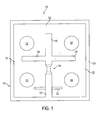
- the resonator filter 100 includes a filter housing 102 and a filter cover 104.
- the resonators are inductively coupled in series such that resonator 106 is coupled to resonator 108, resonator 108 is coupled to resonator 110, and resonator 10 is coupled to resonator 112.
- These resonators are separated from each other by cavity walls 114, 116, 118, and 123 that form a cross-shaped arrangement.
- walls 114, 116, and 118 extend only partially to the perimeter walls 120 of the filter housing 102 leaving a gap 122 therebetween.
- the walls permit inductive coupling between resonators 106-108; 108-110; and 110-112.
- cavity wall 123 extends all the way to the perimeter wall 120. This cavity wall 123 electrically separates the first resonator 106 in the series from the last resonator 112 in the series. Hence resonators 106 and 112 are not inductively coupled in the way that the other resonators are, and are therefore are not electrically adjacent in the series despite being physically adjacent.
- the invention includes an inductive coupler in cavity wall 123 in the form of a notch 134 provided in cavity wall 123 and an associated fine tuning screw 136, shown/in Figure 2.
- the fine tuning screw 136 extends through the filter cover 104 into the notch 134.
- the capacitance cross-coupling effect can be changed by turning the screw from the exterior of the filter 100.
- the filter cover 104 encloses the resonator cavity.
- the filter cover 104 is made of lead, while the housing 102 is made of iron.
- the cross-coupling bar 124 is held in the cavity wall 123 by a collar 138, made of an electrically insulating material such as plastic.
- the tuning screw 1136 extends through the filter cover104 into the notch 134. While notch 134 can be of any height equal to or less than the height of wall 123, in the preferred embodiment the notch provides only fine adjustment of the capacitive effect of the cross-coupling bar 124. Therefore, the height of the notch is only between twenty and fifty percent of the height of the wall 123. Again, however, it should be understood that the invention is not limited to any particular height.
- FIG 4 illustrates additional embodiment of the invention.
- both the bar 124 and the notch 134 are set in the middle of cavity wall 123.
- the tuning notch 134 is provided above the bar 124.
- This embodiment shows a filter which can be easily changed from one capacitive cross-coupling level to another by easily replacing the bar, but which also retains the ability to fine tune the bar 124 once it is set in place by adjusting the tuning screw 136 that extends through the top of the filter cover 104. More specifically, with this arrangement, the insulating collar 138 that holds the bar 124 in place can be easily removed by sliding it out through the slot 134.
Landscapes
- Physics & Mathematics (AREA)
- Electromagnetism (AREA)
- Control Of Motors That Do Not Use Commutators (AREA)
Applications Claiming Priority (2)
| Application Number | Priority Date | Filing Date | Title |
|---|---|---|---|
| US10/024,567 US6836198B2 (en) | 2001-12-21 | 2001-12-21 | Adjustable capacitive coupling structure |
| US24567 | 2001-12-21 |
Publications (2)
| Publication Number | Publication Date |
|---|---|
| EP1321997A2 true EP1321997A2 (de) | 2003-06-25 |
| EP1321997A3 EP1321997A3 (de) | 2003-11-05 |
Family
ID=21821245
Family Applications (1)
| Application Number | Title | Priority Date | Filing Date |
|---|---|---|---|
| EP02028004A Withdrawn EP1321997A3 (de) | 2001-12-21 | 2002-12-13 | Einstellbare kapazitive Einkoppelstruktur |
Country Status (3)
| Country | Link |
|---|---|
| US (1) | US6836198B2 (de) |
| EP (1) | EP1321997A3 (de) |
| CN (1) | CN1427501A (de) |
Cited By (9)
| Publication number | Priority date | Publication date | Assignee | Title |
|---|---|---|---|---|
| EP2421085A1 (de) * | 2010-08-19 | 2012-02-22 | Alcatel Lucent | Filter für Funkfrequenzsignale |
| US9105955B2 (en) | 2011-07-06 | 2015-08-11 | Intel Corporation | Adjustable resonator filter and method for adjusting coupling between resonator cavities |
| CN104871363A (zh) * | 2012-12-24 | 2015-08-26 | 上海贝尔股份有限公司 | 用于与带通滤波器的输入谐振器和/或输出谐振器一起使用的可调节耦合 |
| WO2017096534A1 (zh) * | 2015-12-08 | 2017-06-15 | 华为技术有限公司 | 滤波器的交叉耦合装置和滤波器 |
| WO2017222463A1 (en) * | 2016-06-22 | 2017-12-28 | Syntronic Ab | A method and a system for evaluating a filter body and a method for manufacturing a cavity filter |
| WO2020010984A1 (zh) * | 2018-07-13 | 2020-01-16 | 京信通信系统(中国)有限公司 | 一种容性交叉耦合结构及腔体滤波器 |
| CN111952700A (zh) * | 2019-05-14 | 2020-11-17 | 罗森伯格技术(昆山)有限公司 | 一种交叉耦合滤波器 |
| CN113851803A (zh) * | 2020-06-28 | 2021-12-28 | 大富科技(安徽)股份有限公司 | 一种滤波器及通信设备 |
| CN113964465A (zh) * | 2021-10-15 | 2022-01-21 | 北京微纳星空科技有限公司 | 一种腔体滤波器的可调感性交叉耦合结构 |
Families Citing this family (19)
| Publication number | Priority date | Publication date | Assignee | Title |
|---|---|---|---|---|
| US7327210B2 (en) * | 2004-06-15 | 2008-02-05 | Radio Frequency Systems, Inc. | Band agile filter |
| US7486161B2 (en) * | 2005-12-19 | 2009-02-03 | Universal Microwave Technology, Inc. | Reverse-phase cross coupling structure |
| US7456712B1 (en) * | 2007-05-02 | 2008-11-25 | Cobham Defense Electronics Corporation | Cross coupling tuning apparatus for dielectric resonator circuit |
| US8115574B2 (en) * | 2008-11-21 | 2012-02-14 | Alcatel Lucent | Low pass filter with embedded resonator |
| KR20130015933A (ko) * | 2011-08-05 | 2013-02-14 | 주식회사 케이엠더블유 | 노치 구조를 채용한 무선 주파수 필터 |
| US9812751B2 (en) * | 2013-06-25 | 2017-11-07 | Intel Corporation | Plurality of resonator cavities coupled by inductive apertures which are adjusted by capacitive parts |
| CN104836000B (zh) * | 2014-02-08 | 2018-09-25 | 南京福客通信设备有限公司 | 一种双模介质滤波器 |
| CN104319433A (zh) * | 2014-10-13 | 2015-01-28 | 世达普(苏州)通信设备有限公司 | 具有正负可变换交叉耦合的波导双工器 |
| KR101756124B1 (ko) | 2015-11-30 | 2017-07-11 | 주식회사 케이엠더블유 | 크로스 커플링 노치 구조를 구비한 캐비티 타입의 무선 주파수 필터 |
| WO2018039993A1 (en) * | 2016-08-31 | 2018-03-08 | Telefonaktiebolaget Lm Ericsson (Publ) | Tm dual mode filter |
| CN107707213B (zh) * | 2017-10-19 | 2024-07-02 | 博众优浦(常熟)汽车部件科技有限公司 | 一种可调节长度的拼接式滤波器壳体 |
| KR102503237B1 (ko) | 2018-01-31 | 2023-02-23 | 주식회사 케이엠더블유 | 무선 주파수 필터 |
| KR102116271B1 (ko) * | 2018-04-16 | 2020-05-29 | 주식회사 케이엠더블유 | 노치 구조를 채용한 무선 주파수 필터 |
| KR102319051B1 (ko) | 2019-01-08 | 2021-11-02 | 주식회사 케이엠더블유 | 도파관 필터 |
| WO2020145590A1 (ko) | 2019-01-08 | 2020-07-16 | 주식회사 케이엠더블유 | 도파관 필터 |
| CN113054367A (zh) * | 2019-12-27 | 2021-06-29 | 深圳市大富科技股份有限公司 | 通信设备及其滤波器 |
| CN113054376A (zh) * | 2019-12-27 | 2021-06-29 | 深圳市大富科技股份有限公司 | 一种滤波器及通信设备 |
| CN113054368A (zh) * | 2019-12-27 | 2021-06-29 | 深圳市大富科技股份有限公司 | 通信系统及其滤波器 |
| CN112635943B (zh) * | 2021-01-07 | 2021-10-26 | 中山大学 | 一种频率独立可重构的超大频率比双频带通滤波器 |
Family Cites Families (18)
| Publication number | Priority date | Publication date | Assignee | Title |
|---|---|---|---|---|
| DE2045560C3 (de) * | 1970-09-15 | 1978-03-09 | Standard Elektrik Lorenz Ag, 7000 Stuttgart | Mikrowellenfilter aus quaderförmigen Hohlraumresonatoren |
| JPS5915304A (ja) * | 1982-07-15 | 1984-01-26 | Matsushita Electric Ind Co Ltd | 同軸型誘電体共振器 |
| FR2531815B1 (fr) | 1982-08-10 | 1985-08-02 | Thomson Csf | Filtre passe-bande a resonateurs dielectriques, presentant un couplage negatif entre resonateurs |
| US4453146A (en) * | 1982-09-27 | 1984-06-05 | Ford Aerospace & Communications Corporation | Dual-mode dielectric loaded cavity filter with nonadjacent mode couplings |
| FI88979C (fi) * | 1990-12-17 | 1993-07-26 | Telenokia Oy | Hoegfrekvensbandpassfilter |
| US5126696A (en) * | 1991-08-12 | 1992-06-30 | Trw Inc. | W-Band waveguide variable controlled oscillator |
| JPH0715208A (ja) * | 1993-06-25 | 1995-01-17 | Kokusai Electric Co Ltd | 有極型バンドパスフィルタ |
| IL112465A0 (en) | 1995-01-27 | 1996-01-31 | Israel State | Microwave band pass filter |
| US5841330A (en) * | 1995-03-23 | 1998-11-24 | Bartley Machines & Manufacturing | Series coupled filters where the first filter is a dielectric resonator filter with cross-coupling |
| GB9506866D0 (en) * | 1995-04-03 | 1995-05-24 | Cameron Richard J | Dispersion compensation technique and apparatus for microwave filters |
| US5739690A (en) | 1996-04-04 | 1998-04-14 | Colorado Seminary | Crossed-loop resonator structure for spectroscopy |
| AUPO076796A0 (en) * | 1996-07-01 | 1996-07-25 | Jacobs, Ian Orde Michael | Injection moulding |
| US5781085A (en) * | 1996-11-27 | 1998-07-14 | L-3 Communications Narda Microwave West | Polarity reversal network |
| AUPP353298A0 (en) * | 1998-05-14 | 1998-06-04 | Alcatel Alsthom Compagnie Generale D'electricite | A microwave diplexer arrangement |
| US6081175A (en) * | 1998-09-11 | 2000-06-27 | Radio Frequency Systems Inc. | Coupling structure for coupling cavity resonators |
| US6255919B1 (en) * | 1999-09-17 | 2001-07-03 | Com Dev Limited | Filter utilizing a coupling bar |
| FI114251B (fi) * | 2000-09-22 | 2004-09-15 | Filtronic Lk Oy | Resonaattorisuodatin |
| ITSO20010002A1 (it) | 2001-05-18 | 2002-11-18 | Comtech S R L | Filtro di ordine minimo a cavita' accoppiate per canali televisivi uhf. |
-
2001
- 2001-12-21 US US10/024,567 patent/US6836198B2/en not_active Expired - Lifetime
-
2002
- 2002-12-13 EP EP02028004A patent/EP1321997A3/de not_active Withdrawn
- 2002-12-13 CN CN02156072.2A patent/CN1427501A/zh active Pending
Cited By (12)
| Publication number | Priority date | Publication date | Assignee | Title |
|---|---|---|---|---|
| EP2421085A1 (de) * | 2010-08-19 | 2012-02-22 | Alcatel Lucent | Filter für Funkfrequenzsignale |
| WO2012022559A1 (en) * | 2010-08-19 | 2012-02-23 | Alcatel Lucent | Filter for radio frequency signals |
| US9105955B2 (en) | 2011-07-06 | 2015-08-11 | Intel Corporation | Adjustable resonator filter and method for adjusting coupling between resonator cavities |
| CN104871363A (zh) * | 2012-12-24 | 2015-08-26 | 上海贝尔股份有限公司 | 用于与带通滤波器的输入谐振器和/或输出谐振器一起使用的可调节耦合 |
| CN104871363B (zh) * | 2012-12-24 | 2017-03-15 | 上海贝尔股份有限公司 | 用于与带通滤波器的输入谐振器和/或输出谐振器一起使用的可调节耦合装置 |
| WO2017096534A1 (zh) * | 2015-12-08 | 2017-06-15 | 华为技术有限公司 | 滤波器的交叉耦合装置和滤波器 |
| WO2017222463A1 (en) * | 2016-06-22 | 2017-12-28 | Syntronic Ab | A method and a system for evaluating a filter body and a method for manufacturing a cavity filter |
| US10847863B2 (en) | 2016-06-22 | 2020-11-24 | Syntronic Ab | Method and a system for evaluating a filter body and a method for manufacturing a cavity filter |
| WO2020010984A1 (zh) * | 2018-07-13 | 2020-01-16 | 京信通信系统(中国)有限公司 | 一种容性交叉耦合结构及腔体滤波器 |
| CN111952700A (zh) * | 2019-05-14 | 2020-11-17 | 罗森伯格技术(昆山)有限公司 | 一种交叉耦合滤波器 |
| CN113851803A (zh) * | 2020-06-28 | 2021-12-28 | 大富科技(安徽)股份有限公司 | 一种滤波器及通信设备 |
| CN113964465A (zh) * | 2021-10-15 | 2022-01-21 | 北京微纳星空科技有限公司 | 一种腔体滤波器的可调感性交叉耦合结构 |
Also Published As
| Publication number | Publication date |
|---|---|
| US6836198B2 (en) | 2004-12-28 |
| EP1321997A3 (de) | 2003-11-05 |
| CN1427501A (zh) | 2003-07-02 |
| US20030117241A1 (en) | 2003-06-26 |
Similar Documents
| Publication | Publication Date | Title |
|---|---|---|
| US6836198B2 (en) | Adjustable capacitive coupling structure | |
| KR920010600B1 (ko) | 대역저지 기능을 갖춘 필터 및 송수절환기 | |
| EP0472319B1 (de) | Abstimmbares Bandpass Filter | |
| US5675301A (en) | Dielectric filter having resonators aligned to effect zeros of the frequency response | |
| EP0100350B1 (de) | Keramischer bandfilter | |
| US4963843A (en) | Stripline filter with combline resonators | |
| US8115574B2 (en) | Low pass filter with embedded resonator | |
| EP3104452A1 (de) | Resonator, mikrowellenfrequenzfilter und verfahren für funkfrequenzfilterung | |
| US6720849B2 (en) | High frequency filter, filter device, and electronic apparatus incorporating the same | |
| JPH0690104A (ja) | 誘電体共振器および誘電体共振部品 | |
| KR20220001664A (ko) | 포밍에 의해 튜닝이 이루어지는 rf 캐비티 필터 | |
| US5994978A (en) | Partially interdigitated combline ceramic filter | |
| KR100561694B1 (ko) | 고 유전율 및 높은 선택도 값을 갖는 유전체를 구비하는무선 주파수 필터 | |
| CN217182387U (zh) | 陶瓷波导滤波器 | |
| EP1315228A1 (de) | Dielektrisches filter | |
| KR101187644B1 (ko) | 커플링 튜닝 플레이트를 구비한 대역저지필터 | |
| US6525625B1 (en) | Dielectric duplexer and communication apparatus | |
| EP1191626B1 (de) | Resonatorfilter | |
| KR19980079948A (ko) | 유전체 필터, 유전체 듀플렉서 및 이들의 제조방법 | |
| KR100262499B1 (ko) | 일체형듀플렉서유전체필터 | |
| KR100411202B1 (ko) | 유전체 필터, 유전체 듀플렉서, 및 통신 기기 시스템 | |
| US7796000B2 (en) | Filter coupled by conductive plates having curved surface | |
| KR19990013687A (ko) | 낮은 주파수영역에서의 감쇄비조정이 가능한 일체형 유전체 필터 | |
| KR102202710B1 (ko) | 통신 시스템에서 듀플렉서 및 그를 구비한 송수신기 | |
| US5821835A (en) | Dielectric filter and method of regulating its frequency bandwidth |
Legal Events
| Date | Code | Title | Description |
|---|---|---|---|
| PUAI | Public reference made under article 153(3) epc to a published international application that has entered the european phase |
Free format text: ORIGINAL CODE: 0009012 |
|
| AK | Designated contracting states |
Designated state(s): AT BE BG CH CY CZ DE DK EE ES FI FR GB GR IE IT LI LU MC NL PT SE SI SK TR |
|
| AX | Request for extension of the european patent |
Extension state: AL LT LV MK RO |
|
| PUAL | Search report despatched |
Free format text: ORIGINAL CODE: 0009013 |
|
| AK | Designated contracting states |
Kind code of ref document: A3 Designated state(s): AT BE BG CH CY CZ DE DK EE ES FI FR GB GR IE IT LI LU MC NL PT SE SI SK TR |
|
| AX | Request for extension of the european patent |
Extension state: AL LT LV MK RO |
|
| 17P | Request for examination filed |
Effective date: 20040415 |
|
| 17Q | First examination report despatched |
Effective date: 20040521 |
|
| AKX | Designation fees paid |
Designated state(s): AT BE BG CH CY CZ DE DK EE ES FI FR GB GR IE IT LI LU MC NL PT SE SI SK TR |
|
| STAA | Information on the status of an ep patent application or granted ep patent |
Free format text: STATUS: THE APPLICATION IS DEEMED TO BE WITHDRAWN |
|
| 18D | Application deemed to be withdrawn |
Effective date: 20041201 |