EP1321904B2 - Appareil pour détecter des caractéristiques optiques d'un billet de banque - Google Patents
Appareil pour détecter des caractéristiques optiques d'un billet de banque Download PDFInfo
- Publication number
- EP1321904B2 EP1321904B2 EP02258600.2A EP02258600A EP1321904B2 EP 1321904 B2 EP1321904 B2 EP 1321904B2 EP 02258600 A EP02258600 A EP 02258600A EP 1321904 B2 EP1321904 B2 EP 1321904B2
- Authority
- EP
- European Patent Office
- Prior art keywords
- banknote
- transmitter
- light
- path
- receiver
- Prior art date
- Legal status (The legal status is an assumption and is not a legal conclusion. Google has not performed a legal analysis and makes no representation as to the accuracy of the status listed.)
- Expired - Lifetime
Links
- 230000003287 optical effect Effects 0.000 title claims description 29
- 238000005259 measurement Methods 0.000 claims description 19
- 230000005540 biological transmission Effects 0.000 claims description 15
- 230000001154 acute effect Effects 0.000 claims description 4
- 238000002834 transmittance Methods 0.000 description 9
- 238000005286 illumination Methods 0.000 description 3
- 238000010586 diagram Methods 0.000 description 2
- 238000002310 reflectometry Methods 0.000 description 2
- 239000002390 adhesive tape Substances 0.000 description 1
- 238000004140 cleaning Methods 0.000 description 1
- 239000000463 material Substances 0.000 description 1
- 239000002184 metal Substances 0.000 description 1
- 238000012986 modification Methods 0.000 description 1
- 230000004048 modification Effects 0.000 description 1
- 229920003023 plastic Polymers 0.000 description 1
- 239000004033 plastic Substances 0.000 description 1
- 230000035945 sensitivity Effects 0.000 description 1
- 230000003595 spectral effect Effects 0.000 description 1
Images


Classifications
-
- G—PHYSICS
- G07—CHECKING-DEVICES
- G07D—HANDLING OF COINS OR VALUABLE PAPERS, e.g. TESTING, SORTING BY DENOMINATIONS, COUNTING, DISPENSING, CHANGING OR DEPOSITING
- G07D7/00—Testing specially adapted to determine the identity or genuineness of valuable papers or for segregating those which are unacceptable, e.g. banknotes that are alien to a currency
- G07D7/06—Testing specially adapted to determine the identity or genuineness of valuable papers or for segregating those which are unacceptable, e.g. banknotes that are alien to a currency using wave or particle radiation
- G07D7/12—Visible light, infrared or ultraviolet radiation
- G07D7/121—Apparatus characterised by sensor details
Definitions
- This invention relates to an apparatus for sensing optical characteristics of a banknote.
- Such apparatus is commonly used to determine the authenticity and denomination of banknotes. Often, a banknote is moved along a path past optical transmitters and receivers so that the transmission or reflection characteristics in respective areas of the banknote can be determined by scanning.
- the apparatus may include transmitters which operate in multiple wavelengths, such as red, green, blue and infra-red. (It is noted that the terms “optical” and “light” are used herein to refer to any electromagnetic wavelength, and not merely visible wavelengths.)
- EP-A-0 537 513 relates to a device for measuring banknotes which includes rows of LEDs situated below and above a banknote to be measured.
- a CCD sensor is arranged to detect both diffusely reflected and refracted light from the banknote.
- EP-A-0 718 809 relates to a device for characterising banknotes which includes two light sources, one arranged on each side of a banknote and means for detecting light which is both reflected and transmitted by the banknote.
- US-A-6061121 discloses a banknote processor which includes an illumination device for continually illuminating a sheet to be tested and a receiving device for receiving reflected and filtered light, both devices preferably being arranged along an axis perpendicular to the sheet.
- the illumination device emits divergent light which is reflected on its path to the sheet by various mirrors to increase the uniformity of illumination.
- the present invention relates to an apparatus as set out in claim 1.
- a receiver is arranged to receive both light transmitted through the banknote and light reflected from the banknote. Accordingly, the reflection and transmission characteristics of the banknote can be measured in a simple and economic manner.
- the receiver is located in proximity to a transmitter which transmits the light which is reflected by the banknote to the receiver.
- the arrangement is such that the receiver receives light which is diffusely reflected by the banknote, because this provides a much more representative measurement of the optical characteristics of the banknote than directly reflected light.
- the light paths to and from the banknote are arranged to be inclined with respect to the normal to the plane of the banknote. Because the receiver and transmitter are in proximity, and possibly mounted on the same circuit board, it is easier to make the apparatus more compact.
- a light transmitter and a light receiver are arranged on the same side of the path of a banknote, the receiver being arranged to receive light diffusely reflected by the banknote and travelling in a direction which is substantially opposite to that of the light transmitted by the transmitter. Direct reflection is avoided by arranging for the light paths to be inclined with respect to the normal to the banknote and, preferably, by the light incident on the banknote being collimated so that it does not diverge when considered in at least one plane containing the normal to the banknote.
- the banknote is moved in the scanning direction relative to the incident light and the light is collimated so that it does not diverge when considered in a plane containing both the scanning direction and the normal to the plane of the banknote.
- the incident light is arranged to diverge when viewed in a plane which contains the normal to the banknote and which is transverse to the scanning direction, so that a single transmitter can be used to illuminate a relatively wide area of the banknote as the banknote is moved in the scanning direction past the transmitter.
- each transmitter is associated with at least two receivers, which could be mounted on opposite sides of the transmitter (displaced in a direction transverse to both the scanning direction and the direction normal to the plane of the banknote) for receiving light from respective areas of the banknote.
- the apparatus for measuring the optical characteristics of a banknote includes a reference body and means for moving the body from a first position within the apparatus but out of a banknote path to a second position, possibly within the banknote path, between an optical transmitter and an optical receiver, thereby to permit calibration by measuring the transmission and/or reflection characteristics of the reference body.
- the reference body is used for calibrating the measurement of both transmittance and reflectance characteristics.
- a control means is arranged automatically to move the reference body to the second position in response to particular conditions, for example each time a transaction has been completed using a banknote validator incorporating the apparatus of the invention.
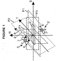
- a banknote 2 lies in a plane P1.
- drive means are provided for conveying the banknote 2 in a scanning direction S which preferably lies in the plane P1 and more preferably is parallel to the length of the banknote 2.
- the direction shown at T is transverse, and particularly perpendicular, to the scanning direction S and also lies within the plane P1 of the banknote 2.
- the direction which is normal to the banknote 2 is shown at N.
- the apparatus includes a first optical device 3 including a light transmitter 4 which is arranged to transmit light to the banknote 2 along a path which is parallel to a plane P2.
- the plane P2 contains the transverse direction T and is located at an angle, for example about 20°, to the normal direction N.
- the device 3 also includes two light receivers 6, 7 positioned in close proximity to, and on respective sides of, the transmitter 4 and displaced from each other in the transverse direction T.
- any light which is reflected from the banknote back in the direction which is substantially reverse to the direction of the transmitted light will be received by the receivers 6, 7 located near the transmitter 4. This will be diffusely reflected light. Any directly (i.e. specularly) reflected light will travel in a direction 8 away from the transmitter 4 and the receivers 6, 7.
- the receivers 6 and 7 are arranged to receive, in addition to light from the transmitter 4 reflected by the banknote, light from the transmitter 4' transmitted through the banknote.
- the receivers 6', 7' can receive light from the transmitter 4 which has been transmitted through the banknote 2. Accordingly, each of the receivers 6, 6', 7, 7' can be used to detect both the reflectance and transmission characteristics of the banknote 2.
- Figure 2 is a side view of the devices 3, 3', the plane of the drawing corresponding to a plane P3 ( Figure 1 ) containing both the scanning direction S and the normal N.
- the light from the transmitter 4 forms a beam which illuminates an area 10 of the banknote.
- a lens 12 (see also Figure 3 ) collimates the light so that there is substantially no divergence of the beam when viewed in the plane P3. Accordingly, all the directly reflected light travelling in the direction 8 will avoid the receivers 6, 7.
- the plane of the drawing corresponds to a plane P4 ( Figures 1 and 2 ) containing both the transverse direction T and the normal N.
- a lens 14, having a skewed optic axis focuses approximately half the area 10, indicated at 10', on to the receiver 6.
- a lens 15, also having a skewed optic axis focuses the other half of the area 10, indicated at 10", on to the receiver 7.
- the arrangement is symmetrical about the optic axis 16 of the transmitter 4.
- a single transmitter 4 is used to illuminate the areas sensed by two separate receivers 6, 7, thus reducing the number of transmitters required. Furthermore, because the light diverges in the planes P2, P4 containing the transverse direction T, but not in the plane P3 containing the scanning direction S, a relatively large area can be illuminated while still avoiding the sensing of direct reflection by the receivers 6, 7.
- the light from the transmitter 4 incident on the banknote and the light from the banknote to the receivers 6, 7 travel in opposite directions in substantially the same path, the small path difference being as a result of the fact that the physical sizes of the transmitter and receivers cause a small angle to be subtended between the light paths at the banknote.
- FIG. 4 illustrates a banknote validator 20 in accordance with the invention.
- the validator has an inlet 22 arranged to receive banknotes which travel along a path 24 to an apparatus 30 which is arranged to test the optical transmission and reflectance characteristics of the banknote.
- a control means 26 is arranged to send signals to and receive signals from the apparatus 30 and to use the received signals to determine the authenticity and the denomination of the banknote.
- the control means 26 is also arranged to send control signals to the apparatus 30 to perform a calibration operation, as will be described below.
- the banknote travels from the apparatus 30 to a gate 28 which is controlled by the control means 26 in dependence upon the type of banknote received.
- the gate can direct the banknote either to a path 32 leading to an outlet 34, or to a path 36 leading to a banknote store 38.
- the apparatus 30 for sensing the optical characteristics of banknotes is shown in more detail in the perspective view of Figure 5 .
- Banknotes are conveyed in the scanning direction S by means of endless belts 40 and sets of rollers 42 at the inlet side 44 of the apparatus and endless belts 46 and sets of rollers 48 at the outlet side 50 of the apparatus.
- the belts 40 and rollers 42 at the inlet side 44 of the apparatus are disposed laterally between the belts 46 and rollers 48 at the outlet side 50 of the apparatus.
- the optical devices 3 (which are identical to the devices 3') are arranged in modules, or units.
- a first unit 52 is disposed above the banknote path at the inlet side 44, and faces a second unit 54 below the banknote path.
- Each unit comprises four optical devices 3 arranged in a line extending in the transverse direction T, each device comprising a transmitter 4 and a pair of receivers 6, 7 arranged as shown in Figures 2 and 3 to sense the reflectance and transmission characteristics in a pair of adjacent areas 10', 10" of the banknotes.
- the units 52 and 54 are arranged for sensing the reflectance and transmittance characteristics of the banknotes in scanned areas which extend between the inlet belts 40.
- Two further units, 56 and 58 are disposed respectively above and below the banknote path at the outlet side 50. These are of similar structure and orientation to the modules 52 and 54, except that they are arranged to scan the areas between the outlet belts 46. Accordingly, as indicated in the plan view of Figure 6 , the units 52, 54, 56 and 58 can scan the entire width of the banknote, each pair of units scanning areas between the areas scanned by the other pair.
- the transmitter 4 and the receivers 6 and 7 are mounted on a common circuit board. If desired, a single circuit board can be used for all the devices 3 within a single module.
- each transmitter comprises an LED package which includes a plurality of dies each of a respective wavelength, for example red, green, blue and infra-red.
- FIG. 5 also shows a pair of calibration units 60, 62.
- Each unit carries four reference bodies 64 and is mounted for pivotal movement about an axis parallel to the transverse direction T so that the body can be pivoted from a non-operational position, as shown in Figure 5 , to an operational position in which each reference body 64 is located between an optical device 3 of one of the units (52 or 56) and the corresponding optical device 3 in another of the units (54 or 58).
- the reference body In this position, the reference body is located in or near the banknote path, and is operable to transmit light from the transmitter 4 of one of the devices to the receivers 6,7 of the opposed device, and to reflect light from the transmitter 4 to its adjacent receivers 6,7.
- Each reference body has predetermined reflection and transmission characteristics, so that calibration of the apparatus can be performed by taking reflectance and transmission measurements while the reference members 60, 62 are in their operational positions.
- the operation of the validator 20 of Figure 4 is as follows.
- a received banknote is delivered to the inlet side 44 of the apparatus 30.
- the reference members 60, 62 are in their non-operational positions at this time.
- the control means 26 continuously checks the light transmitted between the optical units 52, 54 in the inlet section 44 until it detects the significant change caused by the leading edge of the banknote. Further movement of the banknote in the scanning direction S is tracked using an encoder so that the subsequent transmission and reflectance measurements can be associated with respective positions on the banknote.
- the arrangement is such that: (a) dies of different wavelengths are not energised at the same time, (b) reflectance measurements made by each receiver take place when the opposed transmitter on the other side of the banknote path is de-energised, and (c) transmission measurements made by each receiver take place when its adjacent transmitter is de-energised.
- the measurements are initially carried out using the units 52, 54, but similar measurements are also carried out by the units 56, 58 when the leading edge of the banknote has reached these units, as determined by the output of the encoder.
- control means 26 moves the reference members 60, 62 to their operational positions and takes both transmission and reflection calibration measurements which are used to adjust the power supply to the dies of respective wavelengths so that the intensities of the outputs as measured by the receivers complies with a predetermined level, adjust the sensitivities of the receivers and/or alter the processing of the receiver outputs to achieve calibration of the apparatus.
- the calibration operation may be performed only at the end of the transaction which may involve the measurement of one or more banknotes.
- the reference members 60, 62 could be replaced by a sheet, made of for example plastics material, with predetermined reflection and/or transmission characteristics.
- This sheet could be fed along the banknote path, using the normal banknote feeding mechanism, and stored within the banknote apparatus, for example using a dedicated sheet store, so that the reference sheet can be discharged from the store to perform a calibration operation and then returned to the store.
- a cleaning means such as a brush may be provided so that each reference body or the reference sheet is cleaned as it is moved to or from the position in which calibration takes place.
- a modified embodiment could therefore be constructed as shown in Figure 7 .
- This is similar to Figure 2 , except for the provision of additional sensors 9, 9' and focussing lenses 19, 19' for focussing directly-reflected light onto these sensors.
- directly-reflected light By additionally measuring directly-reflected light, it is possible to sense the state of the surface of the banknote. This could be useful for detecting, for example, shiny areas caused by metal strips incorporated into the banknote or by adhesive tape on the banknote. Additionally, or alternatively, the paper quality or texture could be sensed, for example to test the fitness of the banknote to determine whether it should be dispensed.
- the directly-reflected light could also, or alternatively, be used (possibly in combination with a diffuse-reflection measurement) to distinguish between intaglio-printed ink and ink of uniform thickness.
- the provision of sensors for detecting reflected light at different angles i.e. the diffuse-reflectivity sensors 6,7 and the direct-reflectivity sensor 9) could also be useful in detecting optically-variable ink.
- Figure 8 shows another embodiment of the invention, similar to Figure 5 .
- the features described with respect to Figure 5 also apply to the embodiment of Figure 8 , and like reference numbers represent like parts, except as indicated below.
- Figure 8 is shown in a different orientation from that of Figure 5 , incorporates sensors for receiving directly-reflected light and additionally has a modified structure as compared with the arrangement of Figure 5 in order to make it more compact and easier to assemble.
- the transmiters of the optical units 52 and 56 above the banknote path produce light paths which form an obtuse angle with respect to the direction of movement of the banknote; the transmitters of units 54 and 58 produce light paths which form an acute angle with respect to this direction.
- the banknote path is bent and the angles formed by the light paths of the transmitters at the input side are opposite to the angles formed by the corresponding light paths at the output side.
- the transmitters of unit 52 on the left of the path at the inlet side produce light paths L52 which form an obtuse angle with respect to the direction S' of movement of the banknote, whereas the transmitters of the left unit 56 at the outlet produce light paths L56 which form an acute angle with respect to the direction S" of movement.
- the inlet unit 54 uses light paths L54 which are acute with respect to direction S' and the outlet unit 58 uses light paths L58 which are obtuse with respect to direction S".
- the direct-reflection light paths are shown in broken lines, with one of the direct-reflection sensors being shown at 9.
Landscapes
- Health & Medical Sciences (AREA)
- General Health & Medical Sciences (AREA)
- Toxicology (AREA)
- Physics & Mathematics (AREA)
- General Physics & Mathematics (AREA)
- Inspection Of Paper Currency And Valuable Securities (AREA)
Claims (16)
- Appareil pour détecter les caractéristiques optiques d'un billet de banque, l'appareil comportant au moins un premier transmetteur optique (4) situé sur un côté d'un trajet le long duquel un billet de banque (2) peut être déplacé dans une direction de scannage (S) dans le plan (P1) du billet de banque pour illuminer le billet de banque (2) en transmettant de la lumière dans une direction qui est inclinée par rapport à la normale (N) au plan (P1) du billet de banque (2), et au moins un premier récepteur optique (6 ; 7) pour recevoir de la lumière réfléchie de manière diffuse depuis le billet de banque, le premier récepteur optique (6 ; 7) étant adjacent au premier transmetteur optique (4), caractérisé par :le fait que le premier transmetteur (4) est agencé de sorte que la lumière, depuis celui-ci, se déplace parallèlement à un plan de détection (P2) qui contient une direction (T) qui est sensiblement perpendiculaire à la fois à la direction de scannage (S) et à la normale (N) au plan (P1) du billet de banque, et lequel plan de détection (P2) est situé angulairement par rapport à la normale (N) au plan (P1) du billet de banque ;le fait que le premier récepteur (6 ; 7) est agencé de façon à recevoir la lumière depuis le premier transmetteur (4) qui a été réfléchie par le billet de banque et qui se déplace aussi dans ledit plan de détection (P2) dans sensiblement le même trajet, mais dans la direction opposée à la lumière émise par le transmetteur (4), la faible différence de trajet résultant du fait que les tailles physiques du transmetteur et des récepteurs amènent un faible angle à être sous-tendu entre les trajets de lumière au niveau du billet de banque.
- Appareil selon la revendication 1, comportant de plus un deuxième transmetteur optique (4') sur l'autre côté du trajet de billet de banque au premier transmetteur optique (4), le premier récepteur (6 ; 7) étant agencé pour détecter la lumière transmise via le billet de banque (2) depuis le deuxième transmetteur (4').
- Appareil selon la revendication 1, comportant un deuxième récepteur optique (6' ; 7') disposé pour détecter la lumière transmise depuis le deuxième transmetteur (4') et réfléchie de manière diffuse par le billet de banque (2).
- Appareil selon la revendication 3, le deuxième récepteur (6' ; 7') étant disposé pour détecter la lumière transmise via le billet de banque (2) depuis le premier transmetteur (4).
- Appareil selon la revendication 1, dans lequel la lumière depuis le premier transmetteur (4) diverge lorsqu'elle est vue dans ledit plan de détection (P2) lorsqu'elle se déplace vers le billet de banque, de façon à illuminer une zone qui est allongée et qui s'étend dans une direction (T) transversale à la direction de scannage (S).
- Appareil selon la revendication 5, comportant des premier et deuxième récepteurs de lumière (6, 7), tous les deux situés sur ledit un côté du trajet, chaque récepteur de lumière (6, 7) étant disposé pour recevoir de la lumière depuis le premier transmetteur (4) qui a été réfléchie de manière diffuse par une zone (10', 10") du billet de banque, les zones (10', 10") à partir desquelles les premier et deuxième récepteurs (6, 7) reçoivent de la lumière étant déplacées dans une direction (T) transversale à la direction de scannage (S).
- Appareil selon l'une quelconque des revendications précédentes, comportant des moyens de collimatage pour empêcher la lumière provenant du premier transmetteur (4) de diverger lorsqu'elle est vue dans un plan (P3) contenant la direction de scannage (S) et la normale (N) au plan (P1) du billet de banque (2).
- Appareil selon l'une quelconque des revendications précédentes, comportant un récepteur optique supplémentaire (9) disposé pour détecter la lumière transmise depuis le premier transmetteur (4) et réfléchie de manière spéculaire par le billet de banque (2).
- Appareil selon l'une quelconque des revendications précédentes, dans lequel le premier transmetteur et le premier récepteur sont montés sur une carte de circuits imprimés commune.
- Appareil selon l'une quelconque des revendications précédentes, comportant un jeu de dispositifs (3) comportant chacun un premier récepteur (6 ; 7) respectif et un premier transmetteur (4) respectif, chaque dispositif (3) étant ainsi disposé pour scanner une zone respective d'un côté du billet de banque (2), les zones étant déplacées les unes par rapport aux autres dans une direction (T) transversale à la direction de scannage (S).
- Appareil selon la revendication 10, comportant un jeu supplémentaire de dispositifs pour des zones de scannage dudit un côté, chacune desdites zones étant située entre des zones scannées par le premier jeu de dispositifs.
- Appareil selon la revendication 11, dans lequel les jeux respectifs de dispositifs sont disposés en succession le long d'un trajet de billet de banque, un jeu de dispositifs étant adjacent à une première partie du trajet de billet de banque et définissant un trajet de lumière au billet de banque selon un premier angle par rapport à la direction de déplacement du billet de banque et l'autre jeu de dispositifs étant adjacent à une deuxième partie du trajet du billet de banque et définissant un trajet de lumière au billet de banque selon un deuxième angle par rapport à ladite direction de déplacement, les première et deuxième parties de trajet de billet de banque étant inclinées l'une par rapport à l'autre, un des premier et deuxième angles étant aigu et l'autre des premier et deuxième angles étant obtus.
- Appareil selon l'une quelconque des revendications 10 à 12, comportant un jeu supplémentaire de dispositifs pour scanner des zones du côté opposé du billet de banque.
- Appareil selon l'une quelconque des revendications précédentes, comportant de plus un corps (64) de référence et des moyens pour déplacer le corps de référence entre une première position située à l'intérieur de l'appareil, mais en dehors du trajet de billet de banque et une deuxième position dans n'importe lequel desdits trajets de lumière, et des moyens pour réaliser une opération de calibrage sur la base de la sortie d'au moins un récepteur optique (6 ; 7) lorsque le corps de référence est dans la deuxième position.
- Appareil selon la revendication 14, dans lequel l'opération de calibrage calibre des mesures de transmission.
- Appareil selon la revendication 14 ou la revendication 15, dans lequel l'opération de calibrage calibre des mesures de réflectance.
Priority Applications (1)
| Application Number | Priority Date | Filing Date | Title |
|---|---|---|---|
| EP02258600.2A EP1321904B2 (fr) | 2001-12-20 | 2002-12-13 | Appareil pour détecter des caractéristiques optiques d'un billet de banque |
Applications Claiming Priority (3)
| Application Number | Priority Date | Filing Date | Title |
|---|---|---|---|
| EP01310680A EP1321903A1 (fr) | 2001-12-20 | 2001-12-20 | Dispositif pour mesurer des caractéristiques optiques d'un billet de banque |
| EP01310680 | 2001-12-20 | ||
| EP02258600.2A EP1321904B2 (fr) | 2001-12-20 | 2002-12-13 | Appareil pour détecter des caractéristiques optiques d'un billet de banque |
Publications (3)
| Publication Number | Publication Date |
|---|---|
| EP1321904A1 EP1321904A1 (fr) | 2003-06-25 |
| EP1321904B1 EP1321904B1 (fr) | 2010-07-14 |
| EP1321904B2 true EP1321904B2 (fr) | 2020-04-08 |
Family
ID=26077206
Family Applications (1)
| Application Number | Title | Priority Date | Filing Date |
|---|---|---|---|
| EP02258600.2A Expired - Lifetime EP1321904B2 (fr) | 2001-12-20 | 2002-12-13 | Appareil pour détecter des caractéristiques optiques d'un billet de banque |
Country Status (1)
| Country | Link |
|---|---|
| EP (1) | EP1321904B2 (fr) |
Families Citing this family (6)
| Publication number | Priority date | Publication date | Assignee | Title |
|---|---|---|---|---|
| ES2367177T5 (es) † | 2002-12-27 | 2020-07-20 | Nippon Kinsen Kikai Kk | Dispositivo de detección óptico para detectar características ópticas de documentos de valor |
| EP1739634A1 (fr) | 2005-06-29 | 2007-01-03 | MEI, Inc. | Appareil de traitement de billets de banque |
| EP2256700A1 (fr) | 2005-07-27 | 2010-12-01 | MEI, Inc. | Traitement des billets de banque |
| JP5021942B2 (ja) * | 2006-02-28 | 2012-09-12 | 日立オムロンターミナルソリューションズ株式会社 | イメージセンサ及び識別装置及びその補正方法 |
| EP1868166A3 (fr) | 2006-05-31 | 2007-12-26 | MEI, Inc. | Procédé et appareil de validation des billets de banque |
| KR101178001B1 (ko) | 2011-03-28 | 2012-08-28 | 엘지엔시스(주) | 매체 이미지 검출장치, 매체 이미지 검출방법 및 이를 이용한 금융기기 |
Citations (7)
| Publication number | Priority date | Publication date | Assignee | Title |
|---|---|---|---|---|
| US4587434A (en) † | 1981-10-22 | 1986-05-06 | Cubic Western Data | Currency note validator |
| EP0257749A1 (fr) † | 1986-07-04 | 1988-03-02 | De La Rue Systems Limited | Méthode et appareil pour mesurer la réflexion diffuse d'une surface |
| WO1995019019A2 (fr) † | 1994-01-04 | 1995-07-13 | Mars, Incorporated | Detection de faux, notamment de faux billets de banque |
| WO1996036021A1 (fr) † | 1995-05-11 | 1996-11-14 | Giesecke & Devrient Gmbh | Dispositif et procede pour le controle d'objets sous forme de feuilles tels que des billets de banque ou des titres |
| US6101266A (en) † | 1996-11-15 | 2000-08-08 | Diebold, Incorporated | Apparatus and method of determining conditions of bank notes |
| DE19958048A1 (de) † | 1999-12-03 | 2001-06-07 | Giesecke & Devrient Gmbh | Vorrichtung und Verfahren zur Echtheitsprüfung von Banknoten |
| WO2001054077A1 (fr) † | 2000-01-21 | 2001-07-26 | Flex Products, Inc. | Systemes de verification automatisee et procedes d'utilisation avec des dispositifs d'interference optique |
Family Cites Families (4)
| Publication number | Priority date | Publication date | Assignee | Title |
|---|---|---|---|---|
| GB894570A (en) * | 1959-07-15 | 1962-04-26 | British Iron Steel Research | Improvements in or relating to the detection of surface abnormalities |
| IT1250847B (it) * | 1991-10-15 | 1995-04-21 | Urmet Spa | Apparecchio per la validazione di banconote |
| ES2106672B1 (es) * | 1994-12-23 | 1998-06-01 | Azkoyen Ind Sa | Metodo y aparato para la caracterizacion y discriminacion de billetes y documentos de curso legal. |
| DE10005514A1 (de) * | 2000-02-07 | 2001-08-09 | Giesecke & Devrient Gmbh | Vorrichtung und Verfahren zur Überprüfung von Banknoten |
-
2002
- 2002-12-13 EP EP02258600.2A patent/EP1321904B2/fr not_active Expired - Lifetime
Patent Citations (7)
| Publication number | Priority date | Publication date | Assignee | Title |
|---|---|---|---|---|
| US4587434A (en) † | 1981-10-22 | 1986-05-06 | Cubic Western Data | Currency note validator |
| EP0257749A1 (fr) † | 1986-07-04 | 1988-03-02 | De La Rue Systems Limited | Méthode et appareil pour mesurer la réflexion diffuse d'une surface |
| WO1995019019A2 (fr) † | 1994-01-04 | 1995-07-13 | Mars, Incorporated | Detection de faux, notamment de faux billets de banque |
| WO1996036021A1 (fr) † | 1995-05-11 | 1996-11-14 | Giesecke & Devrient Gmbh | Dispositif et procede pour le controle d'objets sous forme de feuilles tels que des billets de banque ou des titres |
| US6101266A (en) † | 1996-11-15 | 2000-08-08 | Diebold, Incorporated | Apparatus and method of determining conditions of bank notes |
| DE19958048A1 (de) † | 1999-12-03 | 2001-06-07 | Giesecke & Devrient Gmbh | Vorrichtung und Verfahren zur Echtheitsprüfung von Banknoten |
| WO2001054077A1 (fr) † | 2000-01-21 | 2001-07-26 | Flex Products, Inc. | Systemes de verification automatisee et procedes d'utilisation avec des dispositifs d'interference optique |
Also Published As
| Publication number | Publication date |
|---|---|
| EP1321904B1 (fr) | 2010-07-14 |
| EP1321904A1 (fr) | 2003-06-25 |
Similar Documents
| Publication | Publication Date | Title |
|---|---|---|
| US7034324B2 (en) | Apparatus for sensing optical characteristics of a banknote | |
| US7173709B2 (en) | Multi-grade object sorting system and method | |
| US8331643B2 (en) | Currency bill sensor arrangement | |
| RU2488886C2 (ru) | Определение пригодности документов с использованием чередующегося освещения | |
| US4587434A (en) | Currency note validator | |
| EP0875045B1 (fr) | Dispositif de lecture | |
| US7812948B2 (en) | Different-kind-of-object detector employing plane spectrometer | |
| US7913832B2 (en) | Method and apparatus for validating bank notes | |
| US8854186B2 (en) | Sheet-of-paper processing device | |
| KR20130103561A (ko) | 광학 센서 및 화상 형성 장치 | |
| US8836926B2 (en) | Optical detector arrangement for document acceptor | |
| KR100597789B1 (ko) | 반사식 광학센서를 이용한 지폐식별장치 | |
| EP1321904B2 (fr) | Appareil pour détecter des caractéristiques optiques d'un billet de banque | |
| EP1248224A2 (fr) | Dispositif et méthode pour détecter des feuilles | |
| EP1429297A1 (fr) | Dispositif de classification de billets de banque | |
| CN101950374B (zh) | 纸币处理机 | |
| EP1429296A1 (fr) | Dispositif de classification de billets de banque | |
| JPH1019776A (ja) | 吸光度測定装置及びそれを備えた分注装置 | |
| EP1675071A1 (fr) | Capteur contrôlé en température | |
| JPH0119196B2 (fr) | ||
| JPH08110964A (ja) | 硬貨判別装置 | |
| JPH08110963A (ja) | 硬貨判別方法 |
Legal Events
| Date | Code | Title | Description |
|---|---|---|---|
| PUAI | Public reference made under article 153(3) epc to a published international application that has entered the european phase |
Free format text: ORIGINAL CODE: 0009012 |
|
| AK | Designated contracting states |
Designated state(s): AT BE BG CH CY CZ DE DK EE ES FI FR GB GR IE IT LI LU MC NL PT SE SI SK TR |
|
| AX | Request for extension of the european patent |
Extension state: AL LT LV MK RO |
|
| 17P | Request for examination filed |
Effective date: 20031223 |
|
| AKX | Designation fees paid |
Designated state(s): DE ES GB IT |
|
| 17Q | First examination report despatched |
Effective date: 20041029 |
|
| RAP1 | Party data changed (applicant data changed or rights of an application transferred) |
Owner name: MEI, INC. |
|
| 111Z | Information provided on other rights and legal means of execution |
Free format text: DEESGBIT Effective date: 20061103 |
|
| 17Q | First examination report despatched |
Effective date: 20041029 |
|
| 111Z | Information provided on other rights and legal means of execution |
Free format text: DE ES GB IT Effective date: 20070802 |
|
| GRAP | Despatch of communication of intention to grant a patent |
Free format text: ORIGINAL CODE: EPIDOSNIGR1 |
|
| GRAS | Grant fee paid |
Free format text: ORIGINAL CODE: EPIDOSNIGR3 |
|
| GRAA | (expected) grant |
Free format text: ORIGINAL CODE: 0009210 |
|
| AK | Designated contracting states |
Kind code of ref document: B1 Designated state(s): DE ES GB IT |
|
| REG | Reference to a national code |
Ref country code: GB Ref legal event code: FG4D |
|
| REF | Corresponds to: |
Ref document number: 60236990 Country of ref document: DE Date of ref document: 20100826 Kind code of ref document: P |
|
| REG | Reference to a national code |
Ref country code: ES Ref legal event code: FG2A Effective date: 20101202 |
|
| PLBI | Opposition filed |
Free format text: ORIGINAL CODE: 0009260 |
|
| 26 | Opposition filed |
Opponent name: GIESECKE & DEVRIENT GMBH Effective date: 20110414 |
|
| PLAX | Notice of opposition and request to file observation + time limit sent |
Free format text: ORIGINAL CODE: EPIDOSNOBS2 |
|
| REG | Reference to a national code |
Ref country code: DE Ref legal event code: R026 Ref document number: 60236990 Country of ref document: DE Effective date: 20110414 |
|
| PLBB | Reply of patent proprietor to notice(s) of opposition received |
Free format text: ORIGINAL CODE: EPIDOSNOBS3 |
|
| RDAF | Communication despatched that patent is revoked |
Free format text: ORIGINAL CODE: EPIDOSNREV1 |
|
| APBM | Appeal reference recorded |
Free format text: ORIGINAL CODE: EPIDOSNREFNO |
|
| APBP | Date of receipt of notice of appeal recorded |
Free format text: ORIGINAL CODE: EPIDOSNNOA2O |
|
| APAH | Appeal reference modified |
Free format text: ORIGINAL CODE: EPIDOSCREFNO |
|
| APBQ | Date of receipt of statement of grounds of appeal recorded |
Free format text: ORIGINAL CODE: EPIDOSNNOA3O |
|
| RAP2 | Party data changed (patent owner data changed or rights of a patent transferred) |
Owner name: MEI, INC. |
|
| REG | Reference to a national code |
Ref country code: DE Ref legal event code: R082 Ref document number: 60236990 Country of ref document: DE Representative=s name: PETERREINS SCHLEY PATENT- UND RECHTSANWAELTE P, DE Ref country code: DE Ref legal event code: R082 Ref document number: 60236990 Country of ref document: DE Representative=s name: PETERREINS SCHLEY PATENT- UND RECHTSANWAELTE, DE |
|
| RAP2 | Party data changed (patent owner data changed or rights of a patent transferred) |
Owner name: CRANE PAYMENT INNOVATIONS, INC. |
|
| PLAB | Opposition data, opponent's data or that of the opponent's representative modified |
Free format text: ORIGINAL CODE: 0009299OPPO |
|
| R26 | Opposition filed (corrected) |
Opponent name: GIESECKE+DEVRIENT CURRENCY TECHNOLOGY GMBH Effective date: 20110414 |
|
| APBU | Appeal procedure closed |
Free format text: ORIGINAL CODE: EPIDOSNNOA9O |
|
| PGFP | Annual fee paid to national office [announced via postgrant information from national office to epo] |
Ref country code: IT Payment date: 20191209 Year of fee payment: 18 |
|
| PUAH | Patent maintained in amended form |
Free format text: ORIGINAL CODE: 0009272 |
|
| STAA | Information on the status of an ep patent application or granted ep patent |
Free format text: STATUS: PATENT MAINTAINED AS AMENDED |
|
| 27A | Patent maintained in amended form |
Effective date: 20200408 |
|
| AK | Designated contracting states |
Kind code of ref document: B2 Designated state(s): DE ES GB IT |
|
| REG | Reference to a national code |
Ref country code: DE Ref legal event code: R102 Ref document number: 60236990 Country of ref document: DE |
|
| PGFP | Annual fee paid to national office [announced via postgrant information from national office to epo] |
Ref country code: ES Payment date: 20200102 Year of fee payment: 18 |
|
| REG | Reference to a national code |
Ref country code: ES Ref legal event code: DC2A Ref document number: 2348863 Country of ref document: ES Kind code of ref document: T5 Effective date: 20210125 |
|
| PG25 | Lapsed in a contracting state [announced via postgrant information from national office to epo] |
Ref country code: IT Free format text: LAPSE BECAUSE OF NON-PAYMENT OF DUE FEES Effective date: 20201213 |
|
| PGFP | Annual fee paid to national office [announced via postgrant information from national office to epo] |
Ref country code: DE Payment date: 20211019 Year of fee payment: 20 Ref country code: GB Payment date: 20211021 Year of fee payment: 20 |
|
| REG | Reference to a national code |
Ref country code: ES Ref legal event code: FD2A Effective date: 20220221 |
|
| PG25 | Lapsed in a contracting state [announced via postgrant information from national office to epo] |
Ref country code: ES Free format text: LAPSE BECAUSE OF NON-PAYMENT OF DUE FEES Effective date: 20201214 |
|
| REG | Reference to a national code |
Ref country code: DE Ref legal event code: R071 Ref document number: 60236990 Country of ref document: DE |
|
| REG | Reference to a national code |
Ref country code: GB Ref legal event code: PE20 Expiry date: 20221212 |
|
| PG25 | Lapsed in a contracting state [announced via postgrant information from national office to epo] |
Ref country code: GB Free format text: LAPSE BECAUSE OF EXPIRATION OF PROTECTION Effective date: 20221212 |