EP1321713B1 - An improved flame tube or liner for a combustion chamber of a gas turbine with low emission of pollutants - Google Patents
An improved flame tube or liner for a combustion chamber of a gas turbine with low emission of pollutants Download PDFInfo
- Publication number
- EP1321713B1 EP1321713B1 EP02258733A EP02258733A EP1321713B1 EP 1321713 B1 EP1321713 B1 EP 1321713B1 EP 02258733 A EP02258733 A EP 02258733A EP 02258733 A EP02258733 A EP 02258733A EP 1321713 B1 EP1321713 B1 EP 1321713B1
- Authority
- EP
- European Patent Office
- Prior art keywords
- apertures
- cylindrical
- liner
- cylindrical region
- combustor
- Prior art date
- Legal status (The legal status is an assumption and is not a legal conclusion. Google has not performed a legal analysis and makes no representation as to the accuracy of the status listed.)
- Revoked
Links
- 238000002485 combustion reaction Methods 0.000 title claims description 75
- 239000003344 environmental pollutant Substances 0.000 title description 11
- 231100000719 pollutant Toxicity 0.000 title description 11
- 238000001816 cooling Methods 0.000 claims description 17
- 230000010355 oscillation Effects 0.000 claims description 5
- 238000013016 damping Methods 0.000 claims description 2
- 239000007789 gas Substances 0.000 description 22
- 239000000446 fuel Substances 0.000 description 7
- MWUXSHHQAYIFBG-UHFFFAOYSA-N nitrogen oxide Inorganic materials O=[N] MWUXSHHQAYIFBG-UHFFFAOYSA-N 0.000 description 3
- 238000011144 upstream manufacturing Methods 0.000 description 3
- 238000013461 design Methods 0.000 description 2
- 238000012423 maintenance Methods 0.000 description 2
- 238000004519 manufacturing process Methods 0.000 description 2
- 238000003466 welding Methods 0.000 description 2
- 230000000694 effects Effects 0.000 description 1
- 239000012530 fluid Substances 0.000 description 1
- 238000002156 mixing Methods 0.000 description 1
- 238000013021 overheating Methods 0.000 description 1
- 238000012546 transfer Methods 0.000 description 1
Images
Classifications
-
- F—MECHANICAL ENGINEERING; LIGHTING; HEATING; WEAPONS; BLASTING
- F23—COMBUSTION APPARATUS; COMBUSTION PROCESSES
- F23R—GENERATING COMBUSTION PRODUCTS OF HIGH PRESSURE OR HIGH VELOCITY, e.g. GAS-TURBINE COMBUSTION CHAMBERS
- F23R3/00—Continuous combustion chambers using liquid or gaseous fuel
- F23R3/42—Continuous combustion chambers using liquid or gaseous fuel characterised by the arrangement or form of the flame tubes or combustion chambers
-
- F—MECHANICAL ENGINEERING; LIGHTING; HEATING; WEAPONS; BLASTING
- F23—COMBUSTION APPARATUS; COMBUSTION PROCESSES
- F23R—GENERATING COMBUSTION PRODUCTS OF HIGH PRESSURE OR HIGH VELOCITY, e.g. GAS-TURBINE COMBUSTION CHAMBERS
- F23R3/00—Continuous combustion chambers using liquid or gaseous fuel
- F23R3/02—Continuous combustion chambers using liquid or gaseous fuel characterised by the air-flow or gas-flow configuration
- F23R3/04—Air inlet arrangements
- F23R3/06—Arrangement of apertures along the flame tube
-
- F—MECHANICAL ENGINEERING; LIGHTING; HEATING; WEAPONS; BLASTING
- F23—COMBUSTION APPARATUS; COMBUSTION PROCESSES
- F23R—GENERATING COMBUSTION PRODUCTS OF HIGH PRESSURE OR HIGH VELOCITY, e.g. GAS-TURBINE COMBUSTION CHAMBERS
- F23R2900/00—Special features of, or arrangements for continuous combustion chambers; Combustion processes therefor
- F23R2900/00014—Reducing thermo-acoustic vibrations by passive means, e.g. by Helmholtz resonators
-
- F—MECHANICAL ENGINEERING; LIGHTING; HEATING; WEAPONS; BLASTING
- F23—COMBUSTION APPARATUS; COMBUSTION PROCESSES
- F23R—GENERATING COMBUSTION PRODUCTS OF HIGH PRESSURE OR HIGH VELOCITY, e.g. GAS-TURBINE COMBUSTION CHAMBERS
- F23R2900/00—Special features of, or arrangements for continuous combustion chambers; Combustion processes therefor
- F23R2900/03044—Impingement cooled combustion chamber walls or subassemblies
Definitions
- the present invention relates to an improved flame tube or "liner" for a combustion chamber of a gas turbine with low emission of pollutants.
- a gas turbine is a machine consisting of a compressor and a turbine with one or more stages, in which these components are interconnected by a rotating shaft and in which a combustion chamber is provided between the compressor and the turbine.
- Air from the external environment is supplied to the compressor where it is pressurized.
- the pressurized air passes through a duct, terminating in a converging portion, into which a set of injectors supplies fuel which is mixed with the air to form a fuel-air mix for combustion.
- the fuel required for the combustion is therefore introduced into the combustion chamber through one or more injectors, supplied from a pressurized network, the combustion process being designed to cause an increase in the temperature and enthalpy of the gas.
- a parallel fuel supply system for generating a pilot flame in the proximity of the mixing duct, is also generally provided in order to improve the stability characteristics of the flame.
- the gas at high temperature and high pressure passes through suitable ducts to reach the various stages of the turbine, which converts the enthalpy of the gas into mechanical energy which is available to a user.
- a gas turbine is known, for example, from U.S. 6098397A . It is well known that the primary considerations in the design of combustion chambers for gas turbines are the flame stability and the control of excess air, the aim being to establish ideal conditions for the combustion.
- a second element influencing the design of combustion chambers of gas turbines is the tendency to make the combustion take place as near as possible to the dome of the combustion chamber.
- the prior art provides for the use of a flame tube or "liner" within the combustion chamber; this has two principal functions.
- the flame is contained within the tube, thus preventing contact with the outer walls of the combustion chamber, in order to avoid overheating.
- the tube decelerates and diffuses the flow of the combustion products, preventing the extinguishing of the flame.
- combustion chambers very commonly have premixing chambers upstream from them, in which air which has previously been used to cool the walls of the combustion chamber is mixed with the fuel.
- This cavity carries pressurized air which circulates in the opposite direction to the flow of combustion products leaving the combustion chamber.
- this air is used as the combustion air to be mixed with the fuel in the premixing chamber and as the cooling air for cooling both the combustion chamber and the combustion products.
- the combustion air passes from the cavity, outside the tube flame, to the premixing chamber through apertures in the outer surface of the latter, and can be constricted.
- the constriction is applied as a function of the quantity of fuel used, in such a way that the ratio between combustion air and fuel is kept constant at the optimal value.
- the flame tube is positioned at the outlet of a truncated conical end connected to the premixing chamber, in the actual combustion region, or the main flame region, of the chamber.
- Cooling air pressurized for example by an axial compressor and circulating in the opposite direction to the flow of combustion products leaving the combustion chamber, flows between the flame tube and the outer walls of the combustion chamber.
- the flame tube is connected by means of a truncated conical end to the premixing chamber, and has a cylindrical structure, which essentially contains two distinct regions.
- a first region located around the main flame, comprises a cylindrical casing with no apertures, while the second, longer, region has a set of apertures or holes and channels for guiding the air passing through them in a direction parallel to the wall of the said region.
- the wall has numerous apertures, producing a flow of air which passes over the interior of the wall and thus cools it.
- the present invention seeks therefore to improve the aforementioned flame tube in such a way that its capacity for cooling in the first region is increased.
- the present invention must therefore seek to provide an improved flame tube or "liner" for a combustion chamber of a gas turbine with low emission of pollutants which also provides good flame stability.
- the present invention also seeks to provide an improved flame tube or "liner" for a combustion chamber of a gas turbine with low emission of pollutants which reduces the pressure oscillations in the combustion chamber, thus acting as an acoustic damper.
- the present invention yet further seeks to provide an improved flame tube or "liner" for a combustion chamber of a gas turbine with low emission of pollutants which ensures high combustion efficiency.
- the present invention also seeks to provide an improved flame tube or "liner" for a combustion chamber of a gas turbine with low emission of pollutants which enables the average life of components subject to high temperatures to be increased.
- the present invention also seeks to provide an improved flame tube or "liner" for a combustion chamber of a gas turbine with low emission of pollutants which is particularly reliable, simple, and functional, and has relatively low production and maintenance costs.
- a combustor for a gas turbine comprising: an outer wall, a liner within the outer wall, said outer wall and said liner defining a cavity therebetween; a premixing chamber; a combustion chamber within said liner; said liner comprising a first cylindrical region around the main flame and a second cylindrical region guiding the combustion products; said liner being positioned at the outlet of said premixing chamber by a truncated conical end, said premixing chamber being supplied with air flowing along said cavity in an opposite direction to a flow of combustion products through the combustor; said first cylindrical region (122) of said liner (112) being surrounded by a cylindrical casing (136) within said outer wall (118) and forming an annular chamber (138) with said liner (112), but said cylindrical casing not surrounding the second cylindrical region (126) of said liner (112), said first cylindrical region (122) of said liner (112) including a first set of apertures (134) for admitting air from said annular chamber (138
- the improved flame tube or "liner" for a combustion chamber of a gas turbine with low emission of pollutants according to the present invention can be made to be substituted easily in combustion chambers which are known in the prior art and are therefore already installed.
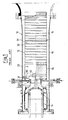
- a combustion chamber indicated as a whole by the number 10, of a gas turbine is shown, a flame tube or "liner" 12 according to the prior art being located inside the chamber.
- a premixing chamber 14 supplied with combustion air which is guided by a cavity 16 located between the flame tube 12 and the outer walls 18 of the combustion chamber 10.
- the flame tube 12 is located at the outlet of a truncated conical end 20 connected to the premixing chamber 14, in the actual combustion region, or main flame region, of the said combustion chamber 10. Cooling air, pressurized by an axial compressor which is not shown in the figure, flows between the flame tube 12 and the outer walls 18 of the combustion chamber 10, in the opposite direction to the flow of combustion products leaving the combustion chamber 10.
- the flame tube 12 has a cylindrical structure, which essentially contains two distinct regions.
- a first cylindrical region 22, located around the main flame, comprises a cylindrical casing 24 with no apertures, while a second, longer, cylindrical region 26 has a set of apertures or holes 28.
- the cooling takes place essentially by means of a layer of air which is adjacent to the inside of the wall and is generated by the passage of air through the apertures 28.
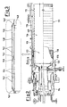
- FIGS 2 and 3 show a combustion chamber, indicated as a whole by the number 110, of a gas turbine, in which is positioned a flame tube or "liner" 112 according to the present invention, where components identical and/or equivalent to those shown in Figure 1 in relation to the prior art have the same reference numbers, increased by 100 in each case.
- a premixing chamber 114 is provided upstream from the flame tube 112, and is supplied with combustion air which is guided by a cavity 116 located between the flame tube 112 and the outer walls 118 of the combustion chamber 110.
- the flame tube 112 is positioned at the outlet of a truncated conical end 120 connected to the premixing chamber 114, in an actual combustion region, or main flame region, of the said combustion chamber 110.
- Cooling air pressurized by an axial compressor which is not shown in the figure, and circulating in the opposite direction to the flow of combustion products leaving the combustion chamber 110, flows between the flame tube 112 and the outer walls 118 of the combustion chamber 110.
- the flame tube 112 has a cylindrical structure, which essentially contains two distinct regions.
- a first cylindrical region 122 is located around the main flame, comprises a cylindrical casing with no apertures, while the second cylindrical region 126, which is longer and is similar to that of the prior art, guides the combustion products and has a set of apertures or holes 128.
- the first cylindrical region 122 has a set of apertures or holes 134, positioned for example at the nodes of a square mesh, and formed in an area close to the truncated conical end 120.
- This region 122 is enclosed by a cylindrical casing 136, which surrounds it, leaving a space for an annular chamber 138.
- the casing 136 has annular joints 140 at both of its ends, which connect it to the first cylindrical region 122 and enclose the annular chamber 138.
- These annular joints 140 are made, for example, by welding shaped sections which are inclined with respect to the axis of the flame tube 112 to the first cylindrical region 122.
- a set of apertures or holes 142 positioned for example at the nodes of square meshes identical to those of the holes 134 of the cylindrical region 122, is formed in the casing 136.
- these holes 142 in the casing 136 are smaller than the holes 134 in the cylindrical region 122, and are staggered with respect to the latter.
- the first cylindrical region 122 also has a part without apertures, and this part is located in a region opposite the truncated conical end 120.
- a separator element 144 of annular form, is provided in the annular chamber 138, between the part of the region 122 having holes 134 and the part without apertures.
- the separator element 144 has at least one gap 146 for connecting two portions of the chamber 138 defined by the said separator element 144.
- This separator element 144 is conveniently formed by welding on to the first cylindrical region 122 a shaped section inclined towards the truncated conical end 120 of the combustion chamber 110.
- a circumferential set of small holes 148 whose sizes are, for example, greater than those of the holes 142 in the casing 136, is formed in the part of the cylindrical region 122 without apertures in the proximity of the annular joint 140.
- Cooling air is pressurized by an axial compressor, which is not shown in the figures, and cools the flame tube 112.
- the air As it cools the flame tube 112, the air is heated and then enters the premixing chamber 114, thus acting as combustion air.
- the cooling is essentially provided by a layer of air which is adjacent to the inside of the wall, and which is generated by the passage of the air through the apertures 128, as in the prior art.
- the cooling is essentially provided by what is known as “impingement cooling”, and not solely by convection as it is in the prior art.
- Impingement cooling is a heat transfer mechanism which is created by the impact of fluids on a surface.
- the pressurized air which passes through the holes 142 in the casing 136 creates a corresponding number of air draughts directed towards the first cylindrical region 122.
- a very thin hydrodynamic and thermal boundary layer is created around the impact regions, as a result of the deceleration of the draught and the increase in pressure.
- the part of the annular chamber 138 where the apertures 134 are provided acts as an acoustic damper to counteract the pressure oscillations occurring within the flame tube 112.
- the set of holes 148 is provided in a region in which the admission of air into the flame tube 112 does not create problems of incomplete combustion and consequent emission of pollutants.
- the apertures 134 must allow only a minimal admission of air, in order to prevent the said pollution problems.
Landscapes
- Engineering & Computer Science (AREA)
- Chemical & Material Sciences (AREA)
- Combustion & Propulsion (AREA)
- Mechanical Engineering (AREA)
- General Engineering & Computer Science (AREA)
- Turbine Rotor Nozzle Sealing (AREA)
- Gas Burners (AREA)
- Combustion Methods Of Internal-Combustion Engines (AREA)
- Engine Equipment That Uses Special Cycles (AREA)
- Pre-Mixing And Non-Premixing Gas Burner (AREA)
Applications Claiming Priority (2)
| Application Number | Priority Date | Filing Date | Title |
|---|---|---|---|
| ITMI20012785 | 2001-12-21 | ||
| IT2001MI002785A ITMI20012785A1 (it) | 2001-12-21 | 2001-12-21 | Tubo di fianna o "liner" migliorato per una camera di combustione di una turbina a gas a basse emissioni inquinanti |
Publications (3)
| Publication Number | Publication Date |
|---|---|
| EP1321713A2 EP1321713A2 (en) | 2003-06-25 |
| EP1321713A3 EP1321713A3 (en) | 2004-07-14 |
| EP1321713B1 true EP1321713B1 (en) | 2008-03-05 |
Family
ID=11448750
Family Applications (1)
| Application Number | Title | Priority Date | Filing Date |
|---|---|---|---|
| EP02258733A Revoked EP1321713B1 (en) | 2001-12-21 | 2002-12-18 | An improved flame tube or liner for a combustion chamber of a gas turbine with low emission of pollutants |
Country Status (9)
| Country | Link |
|---|---|
| US (1) | US6966187B2 (enExample) |
| EP (1) | EP1321713B1 (enExample) |
| JP (1) | JP4362283B2 (enExample) |
| KR (1) | KR100760560B1 (enExample) |
| CA (1) | CA2413655C (enExample) |
| DE (1) | DE60225411T2 (enExample) |
| IT (1) | ITMI20012785A1 (enExample) |
| RU (1) | RU2302586C2 (enExample) |
| TW (1) | TWI312851B (enExample) |
Families Citing this family (15)
| Publication number | Priority date | Publication date | Assignee | Title |
|---|---|---|---|---|
| ITMI20012781A1 (it) * | 2001-12-21 | 2003-06-21 | Nuovo Pignone Spa | Assieme migliorato di camera di pre miscelamento e di camera di combustione, a basse emissioni inquinanti per turbine a gas con combustibile |
| ITMI20032621A1 (it) * | 2003-12-30 | 2005-06-30 | Nuovo Pignone Spa | Sistema di combustione a basse emissioni inquinanti |
| CA2457609A1 (en) * | 2004-02-13 | 2005-08-13 | Alberta Research Council Inc. | Heating solid oxide fuel cell stack |
| US7350619B2 (en) * | 2004-09-23 | 2008-04-01 | Honeywell International, Inc. | Auxiliary power unit exhaust duct with muffler incorporating an externally replaceable acoustic liner |
| EP1832812A3 (de) * | 2006-03-10 | 2012-01-04 | Rolls-Royce Deutschland Ltd & Co KG | Gasturbinenbrennkammerwand mit Dämpfung von Brennkammerschwingungen |
| US8156743B2 (en) * | 2006-05-04 | 2012-04-17 | General Electric Company | Method and arrangement for expanding a primary and secondary flame in a combustor |
| AU2009216835B2 (en) * | 2008-02-20 | 2013-12-05 | General Electric Technology Gmbh | Thermal machine |
| EP2187125A1 (de) * | 2008-09-24 | 2010-05-19 | Siemens Aktiengesellschaft | Vorrichtung und Verfahren zur Dämpfung von Verbrennungsschwingungen |
| US8863525B2 (en) | 2011-01-03 | 2014-10-21 | General Electric Company | Combustor with fuel staggering for flame holding mitigation |
| US20120208141A1 (en) * | 2011-02-14 | 2012-08-16 | General Electric Company | Combustor |
| EP2644995A1 (en) | 2012-03-27 | 2013-10-02 | Siemens Aktiengesellschaft | An improved hole arrangement of liners of a combustion chamber of a gas turbine engine with low combustion dynamics and emissions |
| US20140033726A1 (en) * | 2012-08-06 | 2014-02-06 | Wei Chen | Liner cooling assembly for a gas turbine system |
| EP3189277B1 (en) | 2014-09-05 | 2020-04-15 | Siemens Aktiengesellschaft | Cross ignition flame duct |
| RU2731141C2 (ru) * | 2015-03-30 | 2020-08-31 | Нуово Пиньоне Текнолоджи Срл | Сменное поддерживающее устройство для жаровой трубы камер сгорания газовой турбины |
| JP7262364B2 (ja) | 2019-10-17 | 2023-04-21 | 三菱重工業株式会社 | ガスタービン燃焼器 |
Family Cites Families (16)
| Publication number | Priority date | Publication date | Assignee | Title |
|---|---|---|---|---|
| JPS5129726A (enExample) * | 1974-09-06 | 1976-03-13 | Mitsubishi Heavy Ind Ltd | |
| US4201047A (en) * | 1976-06-10 | 1980-05-06 | Morgan J Randolph | Low emission combustors |
| FR2381911A1 (fr) * | 1977-02-25 | 1978-09-22 | Guidas | Chambre de combustion perfectionnee notamment pour une turbine a gaz |
| GB1570875A (en) * | 1977-03-16 | 1980-07-09 | Lucas Industries Ltd | Combustion equipment |
| US4498288A (en) * | 1978-10-13 | 1985-02-12 | General Electric Company | Fuel injection staged sectoral combustor for burning low-BTU fuel gas |
| US4833881A (en) * | 1984-12-17 | 1989-05-30 | General Electric Company | Gas turbine engine augmentor |
| US5287697A (en) * | 1992-01-02 | 1994-02-22 | General Electric Company | Variable area bypass injector seal |
| RU2062406C1 (ru) * | 1994-04-28 | 1996-06-20 | Акционерное общество "Авиадвигатель" | Камера сгорания газотурбинного двигателя |
| GB2309296B (en) * | 1995-10-11 | 2000-02-09 | Europ Gas Turbines Ltd | Gas turbine engine combuster |
| GB2328011A (en) * | 1997-08-05 | 1999-02-10 | Europ Gas Turbines Ltd | Combustor for gas or liquid fuelled turbine |
| US6098397A (en) * | 1998-06-08 | 2000-08-08 | Caterpillar Inc. | Combustor for a low-emissions gas turbine engine |
| RU2162988C2 (ru) * | 1999-02-22 | 2001-02-10 | Открытое акционерное общество "Авиадвигатель" | Камера сгорания газотурбинной установки |
| GB9926257D0 (en) * | 1999-11-06 | 2000-01-12 | Rolls Royce Plc | Wall elements for gas turbine engine combustors |
| US6446438B1 (en) * | 2000-06-28 | 2002-09-10 | Power Systems Mfg., Llc | Combustion chamber/venturi cooling for a low NOx emission combustor |
| US6427446B1 (en) * | 2000-09-19 | 2002-08-06 | Power Systems Mfg., Llc | Low NOx emission combustion liner with circumferentially angled film cooling holes |
| JP4610800B2 (ja) * | 2001-06-29 | 2011-01-12 | 三菱重工業株式会社 | ガスタービン燃焼器 |
-
2001
- 2001-12-21 IT IT2001MI002785A patent/ITMI20012785A1/it unknown
-
2002
- 2002-12-05 CA CA002413655A patent/CA2413655C/en not_active Expired - Lifetime
- 2002-12-10 TW TW091135661A patent/TWI312851B/zh not_active IP Right Cessation
- 2002-12-17 US US10/320,726 patent/US6966187B2/en not_active Expired - Lifetime
- 2002-12-18 EP EP02258733A patent/EP1321713B1/en not_active Revoked
- 2002-12-18 DE DE60225411T patent/DE60225411T2/de not_active Expired - Lifetime
- 2002-12-20 RU RU2002134607/06A patent/RU2302586C2/ru active
- 2002-12-20 JP JP2002369154A patent/JP4362283B2/ja not_active Expired - Fee Related
- 2002-12-20 KR KR1020020081808A patent/KR100760560B1/ko not_active Expired - Fee Related
Also Published As
| Publication number | Publication date |
|---|---|
| EP1321713A3 (en) | 2004-07-14 |
| JP2003207133A (ja) | 2003-07-25 |
| ITMI20012785A1 (it) | 2003-06-21 |
| DE60225411D1 (de) | 2008-04-17 |
| KR20030053436A (ko) | 2003-06-28 |
| TWI312851B (en) | 2009-08-01 |
| JP4362283B2 (ja) | 2009-11-11 |
| DE60225411T2 (de) | 2009-03-19 |
| CA2413655C (en) | 2009-11-17 |
| US6966187B2 (en) | 2005-11-22 |
| RU2302586C2 (ru) | 2007-07-10 |
| CA2413655A1 (en) | 2003-06-21 |
| US20030118963A1 (en) | 2003-06-26 |
| KR100760560B1 (ko) | 2007-09-20 |
| TW200409886A (en) | 2004-06-16 |
| EP1321713A2 (en) | 2003-06-25 |
Similar Documents
| Publication | Publication Date | Title |
|---|---|---|
| EP1321713B1 (en) | An improved flame tube or liner for a combustion chamber of a gas turbine with low emission of pollutants | |
| EP1143201B1 (en) | Cooling system for gas turbine combustor | |
| US5497611A (en) | Process for the cooling of an auto-ignition combustion chamber | |
| EP1398572B1 (en) | Dual-mode nozzle assembly with passive tip cooling | |
| EP2475933B1 (en) | Fuel injector for use in a gas turbine engine | |
| US3545202A (en) | Wall structure and combustion holes for a gas turbine engine | |
| US6915638B2 (en) | Nozzle with fluted tube | |
| CN105823085B (zh) | 具有混合器的顺序燃烧器组件 | |
| US20090120093A1 (en) | Turbulated aft-end liner assembly and cooling method | |
| EP2966356B1 (en) | Sequential combustor arrangement with a mixer | |
| EP2375160A2 (en) | Angled seal cooling system | |
| JP4362284B2 (ja) | 液体及び/又は気体燃料で動作するガスタービンのための汚染物質低排出の予混合室及び燃焼室の改良された組合せ | |
| KR20100061538A (ko) | 2차 연료 전달 시스템 | |
| US6220015B1 (en) | Gas-turbine engine combustion system | |
| EP1058061B1 (en) | Combustion chamber for gas turbines | |
| CN105972637B (zh) | 具有双壁的燃烧室 | |
| US20110110761A1 (en) | Gas turbine having an improved cooling architecture | |
| EP0676590B1 (en) | Gas turbine engine combustion apparatus | |
| JPH06221562A (ja) | ガスタービン燃焼器 | |
| US9057524B2 (en) | Shielding wall for a fuel supply duct in a turbine engine | |
| EP3225917B1 (en) | Gas turbine combustor with cross fire tube assembly | |
| GB2134243A (en) | Combustion equipment for a gas turbine engine | |
| CN109416180B (zh) | 用于涡轮发动机中的燃烧器组件及其装配方法 | |
| RU2039323C1 (ru) | Камера сгорания | |
| RU2124676C1 (ru) | Способ сжигания топлива в высокотемпературном газотурбинном двигателе и устройство для сжигания топлива в газотурбинном двигателе |
Legal Events
| Date | Code | Title | Description |
|---|---|---|---|
| PUAI | Public reference made under article 153(3) epc to a published international application that has entered the european phase |
Free format text: ORIGINAL CODE: 0009012 |
|
| AK | Designated contracting states |
Designated state(s): AT BE BG CH CY CZ DE DK EE ES FI FR GB GR IE IT LI LU MC NL PT SE SI SK TR |
|
| AX | Request for extension of the european patent |
Extension state: AL LT LV MK RO |
|
| PUAL | Search report despatched |
Free format text: ORIGINAL CODE: 0009013 |
|
| AK | Designated contracting states |
Kind code of ref document: A3 Designated state(s): AT BE BG CH CY CZ DE DK EE ES FI FR GB GR IE IT LI LU MC NL PT SE SI SK TR |
|
| AX | Request for extension of the european patent |
Extension state: AL LT LV MK RO |
|
| RIC1 | Information provided on ipc code assigned before grant |
Ipc: 7F 23R 3/06 B Ipc: 7F 23R 3/54 B Ipc: 7F 23R 3/00 A |
|
| 17P | Request for examination filed |
Effective date: 20050114 |
|
| AKX | Designation fees paid |
Designated state(s): CH DE FR GB LI NL |
|
| 17Q | First examination report despatched |
Effective date: 20060113 |
|
| GRAP | Despatch of communication of intention to grant a patent |
Free format text: ORIGINAL CODE: EPIDOSNIGR1 |
|
| GRAS | Grant fee paid |
Free format text: ORIGINAL CODE: EPIDOSNIGR3 |
|
| GRAA | (expected) grant |
Free format text: ORIGINAL CODE: 0009210 |
|
| AK | Designated contracting states |
Kind code of ref document: B1 Designated state(s): CH DE FR GB LI NL |
|
| REG | Reference to a national code |
Ref country code: GB Ref legal event code: FG4D |
|
| REG | Reference to a national code |
Ref country code: CH Ref legal event code: EP |
|
| REF | Corresponds to: |
Ref document number: 60225411 Country of ref document: DE Date of ref document: 20080417 Kind code of ref document: P |
|
| REG | Reference to a national code |
Ref country code: CH Ref legal event code: NV Representative=s name: SERVOPATENT GMBH |
|
| REG | Reference to a national code |
Ref country code: CH Ref legal event code: NV Representative=s name: SERVOPATENT GMBH |
|
| ET | Fr: translation filed | ||
| PLBI | Opposition filed |
Free format text: ORIGINAL CODE: 0009260 |
|
| PLAX | Notice of opposition and request to file observation + time limit sent |
Free format text: ORIGINAL CODE: EPIDOSNOBS2 |
|
| 26 | Opposition filed |
Opponent name: SIEMENS AKTIENGESELLSCHAFT Effective date: 20081205 |
|
| NLR1 | Nl: opposition has been filed with the epo |
Opponent name: SIEMENS AKTIENGESELLSCHAFT |
|
| PLAF | Information modified related to communication of a notice of opposition and request to file observations + time limit |
Free format text: ORIGINAL CODE: EPIDOSCOBS2 |
|
| PLBB | Reply of patent proprietor to notice(s) of opposition received |
Free format text: ORIGINAL CODE: EPIDOSNOBS3 |
|
| APBM | Appeal reference recorded |
Free format text: ORIGINAL CODE: EPIDOSNREFNO |
|
| APBP | Date of receipt of notice of appeal recorded |
Free format text: ORIGINAL CODE: EPIDOSNNOA2O |
|
| APAH | Appeal reference modified |
Free format text: ORIGINAL CODE: EPIDOSCREFNO |
|
| PLAB | Opposition data, opponent's data or that of the opponent's representative modified |
Free format text: ORIGINAL CODE: 0009299OPPO |
|
| R26 | Opposition filed (corrected) |
Opponent name: SIEMENS AG CT IP DT 2 Effective date: 20081205 |
|
| REG | Reference to a national code |
Ref country code: DE Ref legal event code: R103 Ref document number: 60225411 Country of ref document: DE Ref country code: DE Ref legal event code: R064 Ref document number: 60225411 Country of ref document: DE |
|
| APBU | Appeal procedure closed |
Free format text: ORIGINAL CODE: EPIDOSNNOA9O |
|
| APBQ | Date of receipt of statement of grounds of appeal recorded |
Free format text: ORIGINAL CODE: EPIDOSNNOA3O |
|
| RDAF | Communication despatched that patent is revoked |
Free format text: ORIGINAL CODE: EPIDOSNREV1 |
|
| RDAG | Patent revoked |
Free format text: ORIGINAL CODE: 0009271 |
|
| STAA | Information on the status of an ep patent application or granted ep patent |
Free format text: STATUS: PATENT REVOKED |
|
| PGFP | Annual fee paid to national office [announced via postgrant information from national office to epo] |
Ref country code: DE Payment date: 20131230 Year of fee payment: 12 Ref country code: GB Payment date: 20131227 Year of fee payment: 12 Ref country code: CH Payment date: 20131230 Year of fee payment: 12 |
|
| REG | Reference to a national code |
Ref country code: CH Ref legal event code: PL |
|
| 27W | Patent revoked |
Effective date: 20130910 |
|
| GBPR | Gb: patent revoked under art. 102 of the ep convention designating the uk as contracting state |
Effective date: 20130910 |
|
| PGFP | Annual fee paid to national office [announced via postgrant information from national office to epo] |
Ref country code: NL Payment date: 20131226 Year of fee payment: 12 Ref country code: FR Payment date: 20131217 Year of fee payment: 12 |
|
| REG | Reference to a national code |
Ref country code: DE Ref legal event code: R107 Ref document number: 60225411 Country of ref document: DE Effective date: 20140403 |
|
| PG25 | Lapsed in a contracting state [announced via postgrant information from national office to epo] |
Ref country code: LI Free format text: LAPSE BECAUSE OF THE APPLICANT RENOUNCES Effective date: 20080305 Ref country code: CH Free format text: LAPSE BECAUSE OF THE APPLICANT RENOUNCES Effective date: 20080305 |