EP1321675A1 - Pumpenaggregat - Google Patents
Pumpenaggregat Download PDFInfo
- Publication number
- EP1321675A1 EP1321675A1 EP01130795A EP01130795A EP1321675A1 EP 1321675 A1 EP1321675 A1 EP 1321675A1 EP 01130795 A EP01130795 A EP 01130795A EP 01130795 A EP01130795 A EP 01130795A EP 1321675 A1 EP1321675 A1 EP 1321675A1
- Authority
- EP
- European Patent Office
- Prior art keywords
- light guide
- light
- housing
- pump unit
- housing wall
- Prior art date
- Legal status (The legal status is an assumption and is not a legal conclusion. Google has not performed a legal analysis and makes no representation as to the accuracy of the status listed.)
- Granted
Links
- 230000002093 peripheral effect Effects 0.000 claims description 12
- 239000000835 fiber Substances 0.000 abstract 2
- 238000004519 manufacturing process Methods 0.000 description 6
- 230000005540 biological transmission Effects 0.000 description 4
- 238000007789 sealing Methods 0.000 description 4
- 239000013307 optical fiber Substances 0.000 description 2
- 238000002347 injection Methods 0.000 description 1
- 239000007924 injection Substances 0.000 description 1
- 238000003780 insertion Methods 0.000 description 1
- 230000037431 insertion Effects 0.000 description 1
- 238000009434 installation Methods 0.000 description 1
- 239000004033 plastic Substances 0.000 description 1
- 229920003023 plastic Polymers 0.000 description 1
- 238000005498 polishing Methods 0.000 description 1
- 229920003229 poly(methyl methacrylate) Polymers 0.000 description 1
- 239000004926 polymethyl methacrylate Substances 0.000 description 1
- 238000012805 post-processing Methods 0.000 description 1
- 238000006748 scratching Methods 0.000 description 1
- 230000002393 scratching effect Effects 0.000 description 1
- 210000002105 tongue Anatomy 0.000 description 1
Images

Classifications
-
- F—MECHANICAL ENGINEERING; LIGHTING; HEATING; WEAPONS; BLASTING
- F04—POSITIVE - DISPLACEMENT MACHINES FOR LIQUIDS; PUMPS FOR LIQUIDS OR ELASTIC FLUIDS
- F04D—NON-POSITIVE-DISPLACEMENT PUMPS
- F04D15/00—Control, e.g. regulation, of pumps, pumping installations or systems
- F04D15/0088—Testing machines
-
- F—MECHANICAL ENGINEERING; LIGHTING; HEATING; WEAPONS; BLASTING
- F04—POSITIVE - DISPLACEMENT MACHINES FOR LIQUIDS; PUMPS FOR LIQUIDS OR ELASTIC FLUIDS
- F04D—NON-POSITIVE-DISPLACEMENT PUMPS
- F04D29/00—Details, component parts, or accessories
- F04D29/40—Casings; Connections of working fluid
- F04D29/42—Casings; Connections of working fluid for radial or helico-centrifugal pumps
- F04D29/426—Casings; Connections of working fluid for radial or helico-centrifugal pumps especially adapted for liquid pumps
Definitions
- the invention relates to a pump unit on which at least one Display element is provided.
- Terminal box display elements such as LEDs are provided, which indicate the operating status of the pump set.
- This Display elements can go directly into an opening in a housing wall be used so that they extend out of the housing and are visible from the outside.
- the display elements For example, light-emitting diodes can be provided in the interior of the housing.
- corresponding viewing windows are provided in the housing wall, through which the display element or the one emitted by it Light is visible from the outside.
- the display element itself is then arranged directly behind the viewing window inside the housing or it extends between the display element or the light source and the viewing window an additional light guide for the transmission of the Display element emitted light.
- This configuration also requires a viewing window inserted into the housing wall, what the manufacturing costs elevated. Furthermore, it must be ensured that the viewing window is tightly connected to the surrounding housing wall to prevent intrusion to prevent the moisture. This also increases the assembly effort.
- the display element a light source arranged inside the housing and a light guide on.
- the light source can be, for example, an incandescent lamp or a Be light-emitting diode, which is preferably attached directly to a circuit board, which carries further electronic components.
- the light guide is for example made of acrylic glass and directs that emitted by the light source Light to a desired display position. According to the invention the light guide from the outside into an opening in a housing wall of the Housing inserted and extends into the interior of the housing. Further is at the end of the light guide, which is inside the housing extends, a light entry surface facing the light source is formed.
- the light guide can thus the light emitted by the light source, which enters the interior of the light guide at the light entry surface a point on the housing wall so that the emitted light is visible from the outside.
- the one inserted in the housing wall closes Light guide the opening in the housing wall from the outside.
- the Light guide preferably fixed or held in the opening.
- the light guide thus takes on two functions, namely the light transmission from the light source to the housing wall and to the other the function of the viewing window in the housing wall. It is therefore no longer necessary to provide a viewing window as a separate component, which in the housing wall is attached to the view of a light source behind it or to enable a light guide behind it. To this In this way, the number of components required is reduced, thereby reducing the Manufacturing costs can be reduced, which is particularly evident in the Mass production affects.
- the light guide preferably has at least one conical peripheral section on which on a corresponding conical inner circumferential surface of the opening. Due to the conical design a peripheral surface of the light guide and that formed in the housing wall Opening, there will be a large contact surface between the light guide and created the housing wall.
- the light guide lies with its peripheral surface flat on the conical receptacle in the housing wall. Due to the large contact area between the light guide and the housing wall is a good seal of the opening provided in the housing wall achieved so that additional sealing elements are dispensed with can. This further simplifies production and assembly, since the light guide only has to be inserted from the outside into the housing wall and at the same time seals the opening in the housing.
- the opening in the Housing wall designed so conical that it faces the inside of the Tapered housing. Accordingly, the light guide is designed that the conical peripheral surface faces that end of the light guide tapered, which extends into the interior of the housing.
- the light guide expediently has a length which is greater than the thickness of the housing wall is.
- the light guide extends from the Outside of the housing wall through the housing wall inside the housing so that the light entry surface of the Light guide is arranged as close as possible to the light source.
- latching means provided with which the light guide is locked to the housing wall. This allows the light guide to be on the housing wall only is fixed so that no additional holding devices for fastening of the light guide must be provided inside the housing. To The light guide only has to be attached from the outside into the housing wall be plugged in, then when he has his final Has reached position, locked with the housing wall and thus from this is held in position.
- the light guide further preferably has a peripheral region at one end with a larger diameter, which on the outside of the Housing wall or a recess on the outside of the housing wall is applied. In this way, the opening on the housing wall of completely covered the light guide towards the outside, so that a good Sealing the housing can be achieved. Furthermore, if a Depression is provided on the outside of the housing wall, a planer housing outer surface can be achieved, which makes it possible Insert the light guide flush into a housing surface.
- the latching means are preferably designed such that that they reach behind the housing wall from the inside.
- This will the light guide fixed in the housing such that the housing wall between the larger diameter peripheral area on the outer End of the light guide and the locking means is fixed.
- the light guide in the direction of its longitudinal axis on the housing wall fixed.
- the light guide is thereby in the housing wall fixes that the outer diameter of the light guide the inner diameter corresponds to the opening provided in the housing wall.
- the Latching means are designed, for example, in the form of elastic projections, which extend radially outward from the circumference of the light guide. It However, other configurations are also conceivable, for example in the form of resilient locking tongues. Alternatively, it is possible to use the opening in the Provide housing wall locking projections that correspond to Engage grooves on the light guide.
- the housing in which the light source and the light guide are arranged is, for example, a terminal box of a pump unit.
- the terminal box usually includes the connections and control or. Control elements of the pump set. That means in the terminal box the entire pump electronics is arranged, with the light source is preferably attached directly to a circuit board of the electronics.
- the light entry surface of the light guide is preferably a converging lens educated. In this way the light transmission can be improved especially if the light entry surface is at a distance from the Light source is arranged.
- the converging lens enables one if possible large part of the light emitted by the light source into the light guide initiate.
- the light entry surface can be parallel be arranged to the longitudinal axis of the light guide. This arrangement is particularly useful if the longitudinal axis of the light guide extends parallel to the surface of a circuit board inside the housing.
- the light guide can be inserted into the housing that the light entry surface is attached to one on the circuit board Light source lies.
- the end face of the light guide that is adjacent to the light entry face is preferably designed as a deflection zone obliquely to the longitudinal axis of the light guide.
- the oblique deflection zone or end face serves a similar purpose Prism or mirror to deflect the light through the light entry surface in the Light guide entering light.
- the light entering is through the deflected oblique surface in the direction of the longitudinal axis of the light guide, so that it is then from the opposite outer end of the light pipe existing face can leak.
- This outer face preferably extends normal to the longitudinal axis of the light guide. It is however, it is also possible that the outer end face of the light guide extends obliquely to the longitudinal axis thereof.
- the design of the outer End face of the light guide is preferably to the shape of the outer surface adapted to the housing so that the end face of the light guide inserts flush into the outer surface of the housing.
- the light guide 2 which is shown in Figure 1, has an elongated shape with a substantially circular cross-section. On his front or inner end 4 of the light guide on its lateral peripheral surface a light entry surface 6.
- the light entry surface 6 is lenticular in Formed a converging lens.
- the rear or outer end 8 of the The light guide forms a display element which shows the light guide 2 transmitted light emits to the outside. In the area of the outer end 8 the light guide 2 has a larger diameter, so that a projection 10 extending radially outwards is formed.
- the outer peripheral surface 12 of the light guide 2 has an essentially conical shape. All in all The light guide tapers from the outer surface 8 towards the inner surface 4, so that it enters from the outside into an opening Housing wall can be used. It is also close to the light guide the outer surface 8 is still on one side radially outwards and protrusion 14 extending in the longitudinal direction of the light guide 2, which in a corresponding groove or recess on the housing intervenes to secure the light guide against rotation and in one align certain angular position with respect to its longitudinal axis can.
- FIG 2 shows a top view of that Side of the light guide 2, on which the light entry surface 6 is provided. This is designed as a converging lens to get as much light as possible a light source is emitted to be able to introduce into the light guide.
- Figure 3 shows a rear view of the light guide, i.e. a top view on the side of the light guide 2 facing away from the light entry surface 6 can be seen in Figure 3 and in particular in Figure 4, the end face in Area of the inner end 4 of the light guide 2 as an oblique deflection zone or Deflection surface 16 formed.
- the deflection surface 16 extends essentially at an angle of 45 ° to the longitudinal axis of the light guide and directs light entering the light guide 2 through the light entry surface 6 at an angle of essentially 90 °. That through the deflection surface 16 deflected light is transmitted through the light guide 2 in the direction of its longitudinal axis passed so that it from the end face at the outer end 8 from the Light guide 2 can emerge.
- the end face at the outer end 8 is in hers Design preferably on the outer surface of a housing in which the light guide 2 is to be used, adjusted so that it is flush with the Completes the outer surface of the housing or, for example, as a display element bulges slightly outwards over the outer surface of the housing.
- the deflection zone or deflection surface 16 is opposite it surrounding area of the inner or lower end face into the interior of the light guide 2 set back. This arrangement serves scratching or damaging the deflection zone 16 during handling, To prevent storage and installation of the light guide.
- the Optical fiber is preferably injection molded as a plastic part without a further post-processing such as grinding or Polishing the deflecting surface should take place.
- the deflection surface is arranged so that it is protected from damage is protected. This can be prevented by the set-back arrangement because the edge surrounding the deflection surface 16 at the inner end the light guide 2 a contact of other objects with the deflection surface 16 prevented.
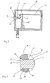
- FIG. 5 shows the manner in which the light guide 2 is inserted into a housing 18 becomes.
- the housing 18 is a terminal box for one Pump, especially circulation pump.
- an opening 20 is provided, into which the light guide 2 is inserted.
- the Opening 20 is designed to correspond to the outer contour of light guide 2, i.e. it has in particular the outside diameter of the Light guide 2 corresponding inner diameter.
- the light guide 2 is inserted from the outside into the opening 20 and extends into the interior of the Housing 18.
- the longitudinal axis of the light guide 2 extends parallel to a circuit board 22, which is arranged inside the housing 18 is and electronic components for controlling the pump wearing.
- On the board 22 there is a light source in the form of a light emitting diode 24 arranged.
- the light-emitting diode 24 extends at right angles to the surface the board 22, the main light emitting surface of the light emitting diode is arranged parallel to the surface of the board 22 so that light from the Light emitting diode 24 is emitted essentially normally to the circuit board 22.
- the light guide 2 is inserted into the housing 18 such that the light entry surface 6 of the light guide 2 is opposite to the light-emitting diode 24. That from the Light emitting diode 24 emits light at the light entry surface 6 in the Light guide 2 a. Then it is on the deflection surface 16 in one Angle of 90 ° deflected so that it is parallel to the longitudinal axis of the light guide 2 is guided through this to the end face at the outer end 8. There it emerges from the light guide 2 so that it can be seen from the outside.
- the light guide 2 forms together with the light-emitting diode 24 a display element.
- the light guide 2 is used for transmission of light, on the other hand replaces the end face at the outer end 8 of the light guide 2, a viewing window provided in the housing wall.
- FIG. 6 shows an enlarged detail view of detail II in FIG Figure 5.
- the light guide 2 is inserted into the opening 20 in the housing 18, that the end face at the outer end 8 of the light guide 2 essentially is flush with the outer surface of the housing 18.
- the peripheral surface 12 is, as explained, conical.
- the opening 20 is on their inner circumference is conical, so that the circumferential surface 12 of the light guide 2 sealing on the inner surface of the opening 20 comes to the plant. This configuration ensures that the Opening 20 through the light guide 2 used, so that additional Sealing elements can be dispensed with.
- the opening 20 has one such a conical configuration that the opening 20 starts out tapered from the outside of the housing to the inside of the housing.
- the opening 20 is included larger diameter so that one towards the outer surface open stage 26 is formed.
- the circumferential projection 10 of the light guide 2 is used.
- the lead 10 comes into play at level 26.
- the projection 10 thus serves together with the locking groove 15, which is formed in the light guide 2, for fixing the light guide 2 in the wall of the housing 18.
- a locking projection 28 which on the inner circumference of the opening 20 is formed in the region of the inner end of the opening 20.
- the device according to the invention enables Design a very simple assembly of the light guide 2nd After assembling the housing 18, the light guide 2 is simply by inserted into the opening 20 in the housing 18 until it is there the locking projections 28 locked or the projection 10 on the step 26 to Facility is coming. In this position, the light guide 2 is fixed to the outer wall of the housing 18 is fixed and held in a predetermined position.
- the projection 14 (not shown in FIGS. 5 and 6) is used for alignment and fixing the angular position of the light guide 2. If the Light guide 2 is completely inserted into the housing 18 in this way, lies the light entry surface 6 over the light emitting diode 24, which on a previously inserted board is fixed. The manufacture and assembly of a Pump unit with the display element according to the invention thus considerably simplified.
Landscapes
- Engineering & Computer Science (AREA)
- Mechanical Engineering (AREA)
- General Engineering & Computer Science (AREA)
- Illuminated Signs And Luminous Advertising (AREA)
Abstract
Description
- Fig. 1
- eine perspektivische Ansicht des Lichtleiters,
- Fig. 2
- eine Draufsicht auf den Lichtleiter gemäß Figur 1,
- Fig. 3
- eine Rückansicht des Lichtleiters gemäß Figuren 1 und 2,
- Fig. 4
- eine Schnittansicht des Lichtleiters entlang Linie 1-1 in Figur 2,
- Fig. 5
- eine Schnittansicht eines Gehäuses mit eingesetztem Lichtleiter,
- Fig. 6
- eine vergrößerte Detailansicht II aus Figur 5.
- 2 -
- Lichtleiter
- 4 -
- inneres Ende
- 6 -
- Lichteintrittsfläche
- 8 -
- äußeres Ende
- 10 -
- Vorsprung
- 12 -
- Umfangsfläche
- 14 -
- Vorsprung
- 15 -
- Rastnut
- 16 -
- Umlenkfläche
- 18 -
- Gehäuse
- 20 -
- Öffnung
- 22 -
- Platine
- 24 -
- Leuchtdiode
- 26 -
- Stufe
- 28 -
- Rastvorsprung
Claims (11)
- Pumpenoggregat, an welchem zumindest ein Anzeigeelement vorgesehen ist, wobei
das Anzeigeelement eine im Inneren eines Gehäuses (18) angeordnete Lichtquelle (24) und einen Lichtleiter (2) aufweist,
der Lichtleiter (2) von außen in eine Öffnung (20) in einer Gehäusewand des Gehäuses eingesetzt ist und sich in das Innere des Gehäuses (18) erstreckt, und
an dem Ende (4) des Lichtleiters (2), welches sich in das Innere des Gehäuses (18) erstreckt, eine der Lichtquelle (24) zugewandte Lichteintrittsfläche (6) ausgebildet ist. - Pumpenaggregat nach Anspruch 1, bei welchem der Lichtleiter (2) zumindest einen konischen Umfangsabschnitt (12) aufweist, welcher an einer korrespondierenden konischen Innenumfangsfläche der Öffnung (20) anliegt.
- Pumpenaggregat nach Anspruch 1 oder 2, bei welchem der Lichtleiter (2) eine Länge aufweist, welche größer als die Dicke der Gehäusewand ist.
- Pumpenaggregat nach einem der vorangehenden Ansprüche, bei welchem an dem Lichtleiter (2) Rastmittel (15) vorgesehen sind, mit denen der Lichtleiter (2) an der Gehäusewand verrastet ist.
- Pumpenaggregat nach einem der vorangehenden Ansprüche, bei welchem der Lichtleiter (2) an einem Ende einen Umfangsbereich (10) mit größerem Durchmesser aufweist, welcher an der Außenseite der Gehäusewand oder einer Vertiefung (26) an der Außenseite der Gehäusewand anliegt.
- Pumpenaggregat nach Ansprüchen 4 und 5, bei welchem die Rastmittel (15) die Gehäusewand von innen hinter greifen.
- Pumpenaggregat nach einem der vorangehenden Ansprüche, bei welchem das Gehäuse (18) ein Klemmenkasten ist.
- Pumpenaggregat nach einem der vorangehenden Ansprüche, bei welchem die Lichteintrittsfläche (6) als Sammellinse ausgebildet ist.
- Pumpenaggregat nach einem dervorangehenden Ansprüche, bei welchem die Lichteintrittsfläche (6) parallel zur Längsachse des Lichtleiters (2) angeordnet ist.
- Pumpenaggregat nach Anspruch 9, bei welchem die der Lichteintrittsfläche (6) benachbarte Stirnfläche (16) des Lichtleiters (2) als Umlenkzone schräg zur Längsachse des Lichtleiters ausgebildet ist.
- Pumpenaggregat nach Anspruch 10, bei welchem die Stirnfläche (16) in einem Winkel von 45° zur Längsachse angeordnet ist.
Priority Applications (2)
| Application Number | Priority Date | Filing Date | Title |
|---|---|---|---|
| DE50115102T DE50115102D1 (de) | 2001-12-23 | 2001-12-23 | Pumpenaggregat |
| EP20010130795 EP1321675B1 (de) | 2001-12-23 | 2001-12-23 | Pumpenaggregat |
Applications Claiming Priority (1)
| Application Number | Priority Date | Filing Date | Title |
|---|---|---|---|
| EP20010130795 EP1321675B1 (de) | 2001-12-23 | 2001-12-23 | Pumpenaggregat |
Publications (2)
| Publication Number | Publication Date |
|---|---|
| EP1321675A1 true EP1321675A1 (de) | 2003-06-25 |
| EP1321675B1 EP1321675B1 (de) | 2009-09-09 |
Family
ID=8179692
Family Applications (1)
| Application Number | Title | Priority Date | Filing Date |
|---|---|---|---|
| EP20010130795 Expired - Lifetime EP1321675B1 (de) | 2001-12-23 | 2001-12-23 | Pumpenaggregat |
Country Status (2)
| Country | Link |
|---|---|
| EP (1) | EP1321675B1 (de) |
| DE (1) | DE50115102D1 (de) |
Cited By (1)
| Publication number | Priority date | Publication date | Assignee | Title |
|---|---|---|---|---|
| EP3835587A1 (de) * | 2019-12-10 | 2021-06-16 | Wilo Se | Steuerungselektronik für eine kreiselpumpe mit wenigstens einem optischen anzeigeelement |
Citations (5)
| Publication number | Priority date | Publication date | Assignee | Title |
|---|---|---|---|---|
| DE2454756A1 (de) * | 1974-11-19 | 1976-05-26 | Hermetic Pumpen Gmbh | Spaltrohrmotorpumpe |
| DE3100861A1 (de) * | 1981-01-14 | 1982-08-12 | Hermetic Pumpen Gmbh | "motor-pumpenaggregat mit einer ueberwachungseinrichtung fuer das laeufer-axialspiel" |
| DE3209554C1 (de) | 1982-03-16 | 1983-10-13 | Bosch Siemens Hausgeraete | Wasserführendes Haushaltgerät |
| DE3811547A1 (de) * | 1988-04-06 | 1989-10-19 | Bosch Siemens Hausgeraete | Anzeigevorrichtung bei einer waeschebehandlungs- oder geschirrspuelmaschine |
| EP0510362A1 (de) * | 1991-04-23 | 1992-10-28 | WILO GmbH | Elektromotor, insbesondere Spaltrohrmotor für eine Kreiselpumpe oder einen Lüfter |
-
2001
- 2001-12-23 EP EP20010130795 patent/EP1321675B1/de not_active Expired - Lifetime
- 2001-12-23 DE DE50115102T patent/DE50115102D1/de not_active Expired - Lifetime
Patent Citations (5)
| Publication number | Priority date | Publication date | Assignee | Title |
|---|---|---|---|---|
| DE2454756A1 (de) * | 1974-11-19 | 1976-05-26 | Hermetic Pumpen Gmbh | Spaltrohrmotorpumpe |
| DE3100861A1 (de) * | 1981-01-14 | 1982-08-12 | Hermetic Pumpen Gmbh | "motor-pumpenaggregat mit einer ueberwachungseinrichtung fuer das laeufer-axialspiel" |
| DE3209554C1 (de) | 1982-03-16 | 1983-10-13 | Bosch Siemens Hausgeraete | Wasserführendes Haushaltgerät |
| DE3811547A1 (de) * | 1988-04-06 | 1989-10-19 | Bosch Siemens Hausgeraete | Anzeigevorrichtung bei einer waeschebehandlungs- oder geschirrspuelmaschine |
| EP0510362A1 (de) * | 1991-04-23 | 1992-10-28 | WILO GmbH | Elektromotor, insbesondere Spaltrohrmotor für eine Kreiselpumpe oder einen Lüfter |
Cited By (1)
| Publication number | Priority date | Publication date | Assignee | Title |
|---|---|---|---|---|
| EP3835587A1 (de) * | 2019-12-10 | 2021-06-16 | Wilo Se | Steuerungselektronik für eine kreiselpumpe mit wenigstens einem optischen anzeigeelement |
Also Published As
| Publication number | Publication date |
|---|---|
| EP1321675B1 (de) | 2009-09-09 |
| DE50115102D1 (de) | 2009-10-22 |
Similar Documents
| Publication | Publication Date | Title |
|---|---|---|
| DE102012107833B4 (de) | Beleuchtungseinrichtung und Rückblickeinrichtung | |
| DE102012107834B4 (de) | Beleuchtungseinrichtung für Innen- oder Außenspiegel eines Kraftfahrzeugs mit einer Lichtleitereinheit, die nutenartige Vertiefungen zur Festlegung einer Leuchteinheit aufweist | |
| EP2738043A1 (de) | Gehäuse und Anzeigeeinrichtung | |
| EP2816276A2 (de) | Kraftfahrzeug mit einer Leuchtvorrichtung | |
| DE102006035842B9 (de) | Fahrzeugleuchte mit einer einstückigen Lichtleiter-Blenden-Einheit | |
| DE10119910C1 (de) | Gehäuse | |
| EP1321675B1 (de) | Pumpenaggregat | |
| DE29900087U1 (de) | Kabeldurchführung | |
| DE4219901A1 (de) | Lichtwellenleiter-Abschlußhülse | |
| WO2007124883A1 (de) | Lichtwellenleitersteckerteil | |
| EP3853518B1 (de) | Lichtmodul, insbesondere zur verwendung in einer beleuchtungsvorrichtung für ein kraftfahrzeug | |
| EP2196982B1 (de) | Segmentanzeige mit einem Lichtleiter | |
| EP2994694B1 (de) | Plattenförmiges reflektorelement für led-platine | |
| DE102010001526B4 (de) | Beleuchtungseinheit mit einem Prisma für ein Fahrzeug | |
| DE102004051326B4 (de) | Gehäuse für Lichtschranken, Reflexionslichtschranken, Lichttester oder Distanzsensoren | |
| DE20004194U1 (de) | Steckverbinder zur Leuchtenhalterung | |
| DE10205810B4 (de) | Vorrichtung zum Öffnen und Schliessen einer Öffnung mit einer Befestigungsvorrichtung für einen Lichtwellenleiter | |
| EP3835587B1 (de) | Steuerungselektronik für eine kreiselpumpe mit wenigstens einem optischen anzeigeelement | |
| EP2940374B1 (de) | Optisches element für eine lichtquelle einer leuchte, sowie leuchte | |
| EP0901029A1 (de) | Optisches Bauelement | |
| DE202018003092U1 (de) | Elektronisches Gerät mit Lichtleiter | |
| EP4614061A1 (de) | Beleuchtungssystem | |
| DE102022134104A1 (de) | Gehäuseteil für einen Sensor | |
| DE202024104812U1 (de) | Feuchtraumleuchte | |
| DE102007033195A1 (de) | Sensorgesteuerte Beleuchtungsvorrichtung |
Legal Events
| Date | Code | Title | Description |
|---|---|---|---|
| PUAI | Public reference made under article 153(3) epc to a published international application that has entered the european phase |
Free format text: ORIGINAL CODE: 0009012 |
|
| AK | Designated contracting states |
Designated state(s): AT BE CH CY DE DK ES FI FR GB GR IE IT LI LU MC NL PT SE TR |
|
| AX | Request for extension of the european patent |
Extension state: AL LT LV MK RO SI |
|
| 17P | Request for examination filed |
Effective date: 20030725 |
|
| AKX | Designation fees paid |
Designated state(s): DE FR GB IT |
|
| 17Q | First examination report despatched |
Effective date: 20080627 |
|
| GRAP | Despatch of communication of intention to grant a patent |
Free format text: ORIGINAL CODE: EPIDOSNIGR1 |
|
| GRAS | Grant fee paid |
Free format text: ORIGINAL CODE: EPIDOSNIGR3 |
|
| GRAA | (expected) grant |
Free format text: ORIGINAL CODE: 0009210 |
|
| AK | Designated contracting states |
Kind code of ref document: B1 Designated state(s): DE FR GB IT |
|
| REG | Reference to a national code |
Ref country code: GB Ref legal event code: FG4D Free format text: NOT ENGLISH |
|
| REF | Corresponds to: |
Ref document number: 50115102 Country of ref document: DE Date of ref document: 20091022 Kind code of ref document: P |
|
| PLBE | No opposition filed within time limit |
Free format text: ORIGINAL CODE: 0009261 |
|
| STAA | Information on the status of an ep patent application or granted ep patent |
Free format text: STATUS: NO OPPOSITION FILED WITHIN TIME LIMIT |
|
| 26N | No opposition filed |
Effective date: 20100610 |
|
| REG | Reference to a national code |
Ref country code: FR Ref legal event code: PLFP Year of fee payment: 15 |
|
| REG | Reference to a national code |
Ref country code: FR Ref legal event code: PLFP Year of fee payment: 16 |
|
| REG | Reference to a national code |
Ref country code: FR Ref legal event code: PLFP Year of fee payment: 17 |
|
| PGFP | Annual fee paid to national office [announced via postgrant information from national office to epo] |
Ref country code: GB Payment date: 20201222 Year of fee payment: 20 Ref country code: FR Payment date: 20201217 Year of fee payment: 20 |
|
| PGFP | Annual fee paid to national office [announced via postgrant information from national office to epo] |
Ref country code: DE Payment date: 20201215 Year of fee payment: 20 |
|
| PGFP | Annual fee paid to national office [announced via postgrant information from national office to epo] |
Ref country code: IT Payment date: 20201230 Year of fee payment: 20 |
|
| REG | Reference to a national code |
Ref country code: DE Ref legal event code: R071 Ref document number: 50115102 Country of ref document: DE |
|
| REG | Reference to a national code |
Ref country code: GB Ref legal event code: PE20 Expiry date: 20211222 |
|
| PG25 | Lapsed in a contracting state [announced via postgrant information from national office to epo] |
Ref country code: GB Free format text: LAPSE BECAUSE OF EXPIRATION OF PROTECTION Effective date: 20211222 |