EP1321652B1 - Verfahren zur Regelung des Kraftstofftankunterdrucks eines Fahrzeugs - Google Patents
Verfahren zur Regelung des Kraftstofftankunterdrucks eines Fahrzeugs Download PDFInfo
- Publication number
- EP1321652B1 EP1321652B1 EP20020293193 EP02293193A EP1321652B1 EP 1321652 B1 EP1321652 B1 EP 1321652B1 EP 20020293193 EP20020293193 EP 20020293193 EP 02293193 A EP02293193 A EP 02293193A EP 1321652 B1 EP1321652 B1 EP 1321652B1
- Authority
- EP
- European Patent Office
- Prior art keywords
- tank
- gas
- fuel
- negative pressure
- res
- Prior art date
- Legal status (The legal status is an assumption and is not a legal conclusion. Google has not performed a legal analysis and makes no representation as to the accuracy of the status listed.)
- Expired - Fee Related
Links
Images


Classifications
-
- F—MECHANICAL ENGINEERING; LIGHTING; HEATING; WEAPONS; BLASTING
- F02—COMBUSTION ENGINES; HOT-GAS OR COMBUSTION-PRODUCT ENGINE PLANTS
- F02M—SUPPLYING COMBUSTION ENGINES IN GENERAL WITH COMBUSTIBLE MIXTURES OR CONSTITUENTS THEREOF
- F02M25/00—Engine-pertinent apparatus for adding non-fuel substances or small quantities of secondary fuel to combustion-air, main fuel or fuel-air mixture
- F02M25/08—Engine-pertinent apparatus for adding non-fuel substances or small quantities of secondary fuel to combustion-air, main fuel or fuel-air mixture adding fuel vapours drawn from engine fuel reservoir
- F02M25/089—Layout of the fuel vapour installation
-
- F—MECHANICAL ENGINEERING; LIGHTING; HEATING; WEAPONS; BLASTING
- F02—COMBUSTION ENGINES; HOT-GAS OR COMBUSTION-PRODUCT ENGINE PLANTS
- F02D—CONTROLLING COMBUSTION ENGINES
- F02D41/00—Electrical control of supply of combustible mixture or its constituents
- F02D41/0025—Controlling engines characterised by use of non-liquid fuels, pluralities of fuels, or non-fuel substances added to the combustible mixtures
- F02D41/003—Adding fuel vapours, e.g. drawn from engine fuel reservoir
- F02D41/0045—Estimating, calculating or determining the purging rate, amount, flow or concentration
Definitions
- the present invention relates to a method for determining and regulation of the vacuum in an automobile fuel tank generated by the purge of the fuel vapor absorber.
- the vehicle automobile is fitted with, among other things, a fuel-powered engine stored in the fuel tank, a fuel level gauge, of a fuel vapor absorber, of the circuits necessary for purging the fuel vapor absorber, an electromechanical actuator, which is intended to regulate the purging of the fuel vapor absorber, and which is located between the latter and the engine intake manifold on one of the circuits mentioned, and an electronic computer which determines and generates a control signal of said electromechanical actuator.
- the fuel vapor absorber simply referred to as absorber in the following (in English: canister), is presented as a receptacle which stores hydrocarbon vapors by means of elements which are permeable, for example activated carbon. It is generally provided with three orifices: one for connection with the tank, one and one for venting.
- connection port of the absorber is connected to the tank by means of a permeable circuit which is called a link circuit.
- a permeable circuit which is called a link circuit.
- the absorber has a certain storage capacity. When this capacity is reached, it is said that the absorber is saturated. In order to avoid saturation and therefore the release of hydrocarbons into the ambient air via the in the open air, it is necessary to regenerate the absorption elements. II is known that regeneration takes place when the engine is in that a set of pipes should be used, that this is called the purge circuit, which connects the suction port of the absorber to the engine intake manifold.
- the movement of the engine pistons creates a depression in the intake manifold, which allows, by difference with atmospheric pressure, to establish an air flow between the vent hole and the intake manifold that scans the absorption elements; the air takes care of the fuel contained in the absorber and the fuel mixture thus obtained is sucked up by the engine to be burned there.
- connection and suction ports are therefore located close to one of the other ; they can be placed in the same area of the absorber above the absorption elements; or one of (the two) orifices can (wind) penetrate slightly within the absorption elements, however the separation between the connection and suction ports remains weak compared to the separation of these orifices with that of the air vent free.
- the fuel mixture supplied by the absorber purge must not induce detrimental wealth differences in the engine cylinders for compliance with standards on pollutant emissions from the engine.
- this supply must be controlled and limited by a device comprising an electromechanical actuator, for example a solenoid valve, controlled by the electronic computer and which is integrated into the circuit purge, control means programmed in the computer among other things determine and generate the signal control of said electromechanical actuator, simply called actuator in the following.
- the actuator can have several intermediate positions between a complete closure, i.e. an infinite pressure drop in the purge circuit, and, maximum opening, i.e. a minimum (but not zero) pressure drop of the purge. It is therefore necessary to reduce the opening of the actuator to reduce the contribution of the fuel mixture.
- the case should be considered general or the actuator has several intermediate positions openings; and that those that are driven by a duty cycle are assimilated, the opening position is given by the value of the opening cyclic report noted RCO.
- the actuator is opened gradually over by means of an opening step.
- the same is true for closing, except in some cases, not detailed, or a brutal and total closure is carried out.
- the actuator is closed, as the ventilation valve remains closed then a depression is maintained in the tank, and it evolves according to a possible leak.
- the information from the pressure sensor allows process the pressure rise in the tank and detect the importance of the leak.
- the object of the present invention is to overcome the drawbacks of the art by proposing a method for estimating and regulating the pressure in a motor vehicle tank to limit the depression in a tank at a determined value while retaining a possibility of purging the absorber.
- a method for estimating and regulating the pressure in a motor vehicle tank to limit the depression in a tank at a determined value while retaining a possibility of purging the absorber.
- Applied to a vehicle fitted with a pressure sensor intended for a tank tightness diagnosis it also makes it possible to diagnose the correct functioning of the pressure. Too much depression can cause damage to the fuel tank and related components such as the fuel pump.
- FIGS. 8a and 8b represent a diagram of the procedure for calculation of the estimate of the depression in the tank.
- the static depression created at the connection hole of the absorber is mainly a function of the static pressure in the engine intake manifold, static pressure at the venting piece, trivially atmospheric pressure, the pressure drop between the suction and vent openings in function of the permeability of all the absorption elements, construction characteristics of the absorber), pressure drop (possibly non-zero) between the suction and connection orifices, of the pressure drop of the purge circuit depending on the opening of the the actuator, with a necessary and variable delay in stabilizing this depression, physical characteristics and temperature of the mixture gas passing through the purge circuit.
- the direction and flow of the flow which is established in the circuit of connection are mainly functions of the depression at the level of the orifice of the absorber, of the depression in the tank, of the loss of load of this circuit, and of the physical characteristics and the temperature of the gas mixture which passes through the connection circuit.
- the direction and the gas flow in the link circuit are mainly functions of the following parameters: static pressure in the engine intake manifold, the pressure static at the vent connector, trivially the pressure atmospheric pressure loss between the suction ports and venting depending on the pressure drop (possibly nuon between the suction and connection orifices, the pressure drop of the purge circuit according to the actuator control signal, the depression in the tank, the pressure drop in the connection circuit, and physical characteristics and temperatures of the gas mixture passing through the connection and purge circuits, due to the necessary and variable delay to the stabilization of the static depression at the connection orifice the absorber.
- the time required for stabilization of depression in the tank is variable and is mainly a function of the following parameters : the mass flow which passes through the link circuit and therefore mainly from the nine parameters indicated above, the volume of gas in the tank, considering that the variation in the volume of a liquid, depending on the pressure, is negligible compared to that of a gas, the physical characteristics and the temperature of the gas in the tank.
- the purpose of the method according to the invention is, in particular, to estimate in open loop and permanently the vacuum present in the tank.
- an iterative model is used, whose time step is judiciously chosen, which calculates the mass of gas which passes through the link circuit, and which associated with a calculation of the volume of gas contained in the tank, allows to calculate the mass of gas present in the tank and therefore the value of depression.
- the construction of the model is based on the preliminary analysis previously mentioned, however, it is possible to bring certain simplifications.
- the model presented below considers some parameters as constants, because their variations do not cause significant estimation error.
- the gas mixture which passes through the connection and purge circuits as well as that present in the tank are considered to have the same homogeneous and constant composition, to the same temperature considered a constant, and the pressure atmospheric is also considered a constant. Consequently, the model uses, a density value of gas, a constant of gases, a gas temperature and an atmospheric pressure which are constants to be defined judiciously. Finally, the model uses following hypotheses: the gas is perfect, the transformations are isothermal, and the variation of the tank volume as a function of the pressure is negligible (i.e. negligible deformation of the walls).
- the volume of gas in the tank and its associated components can be easily determined from the filling of this tank and known characteristics of its construction such as: maximum volume of fuel that can be contained, dead volume (residual volume of gas when the tank is full to the maximum), etc.
- the filling level of the fuel tank can be known: 1) by means of the gauge fuel, already present on the vehicle, including the information retrieved by the computer or this strategy is programmed, either directly by a wired connection, either indirectly via another computer mounted on the vehicle and multiplexing of the two computers, 2) possibly by means the fuel consumption of the engine.
- the calculation model begins with the initialization of the depression in the tank, denoted ⁇ P res .
- Mgaz_ref res (t i ) Vgaz res (t i ) ⁇ [P atmo - ⁇ P res (t i-1 )] / (r ⁇ T)
- the mass of reference gas Mgaz_ref res is calculated at each calculation step in order to take into account 1) the evolution of the fuel level in the tank and 2) the level fluctuations which may be present even if the information from the fuel gauge is smoothed. It is assumed that the fluctuations vary over time, around the actual level, so the mass of reference gas will fluctuate over time around its actual value. Consequently, the depression in the tank which will be estimated subsequently will remain around its real value.
- Mgaz_ref res a mass of gas ⁇ Mgaz gen which represents the mass of gas generated by vaporization during the time step ⁇ t is added to it and a mass flow value ⁇ Mgaz res which crosses the connection circuit during this same step of time, it is added to or subtracted from it depending on the direction of gas flow in the connection circuit.
- ⁇ Mgaz res is due to the purging of the canister.
- ⁇ Mgaz gen can be estimated in several non-detailed ways, for example by means of a formulation which may be empirical, semi-empirical or experimental.
- ⁇ Mgaz res can therefore be calculated directly using the vacuum values in the tank ⁇ P res and the vacuum value in the intake manifold ⁇ P coll . Given the pressure relationships observed, the Barré - St Venant formula is used. A correction coefficient ⁇ on the equivalent section is used to calibrate the model.
- the device does not include a ventilation valve, or if it has one and it is in the open position, then the mass flow which passes through the solenoid valve is taken on the one hand from the atmosphere via the setting in the open air of the absorber and on the other hand of the tank.
- ⁇ Mgaz res is therefore calculated, inter alia by means of the values of depressions at the ends of the connection circuit.
- ⁇ Mgaz res (t i ) ⁇ ⁇ Se ⁇ 2 ⁇ ⁇ gaz ⁇
- the Barré-St Venant formula can be used which gives the following equation in order to calculate the mass flow rate ⁇ Mgaz res during a time ⁇ t: Yes
- ⁇ P res is the value sought, this is why it is advisable to use the value estimated at the previous calculation step.
- ⁇ P can must be known and can be determined by means of calculations and parameters duly programmed in the calculator, a method of which is specified below:
- the parameters are the results of measurements carried out on elements conforming to those used by the vehicle as follows: under atmospheric pressure P atmo and the gas temperature T chosen, the test is carried out either on a test bench or directly on the vehicle; the purge circuit which includes the actuator connects the suction orifice of the absorber to the intake manifold of the engine as described above.
- the absorber is optionally equipped with a ventilation valve on the vent hole, in this case it is in the open position.
- the connection circuit is eliminated and it is replaced by a static pressure sensor fixed on the connection orifice of the absorber.
- actuator control signals which each characterize an opening position of the latter, and, for different manifold depressions ⁇ P coll , the depression ⁇ P can is measured after stabilization of its value at a constant.
- the control signal denoted SC
- SC can be characterized by one or more parameters, for example: voltage, command frequency, opening duty cycle, etc.
- PSC j the j th of the n parameters used to describe the signal SC. From the measurements, a matrix of values of ⁇ P can is obtained as a function of several vectors of values of ⁇ P coll and of the PSC j parameter (s) of the control signal:
- the parameters programmed in the computer are the matrix [ ⁇ P can ], the vector [ ⁇ P coll ] and the n vectors [PSC j ].
- the value of ⁇ P can is determined at the instant tien function of these parameters and of the values ⁇ P coll and of (the) PSC j determined (s) by the calculator beforehand at the same calculation step t i .
- the vacuum in the intake manifold ⁇ P coll is obtained by the difference between the atmospheric pressure P atmo defined above and the static pressure in the intake manifold, which is known for the needs of engine regulation and resulting either from the acquisition information from a static pressure sensor placed on the intake manifold, or by reconstitution of information (s) from one (of several) other sensor (s).
- the constant Se can be replaced by two constants Se 1 and Se 2 , and use one or the other depending on the direction of flow, determined by the equation ( E.6), because the link circuit generally includes one (several) mechanical system (s) permeable (s) such as a safety valve during the overturning of the vehicle (English acronym: ROV) which can (can) cause a different equivalent section depending on the direction of flow. These equivalent sections can be measured.
- the coefficient ⁇ can be replaced by two distinct coefficients ⁇ 1 and ⁇ 2 .
- the constant Se and the coefficient ⁇ are replaced by the terms Se 2 and ⁇ 3 when the closing of the solenoid valve is sudden. In fact, it is better to calculate ⁇ Mgaz res no longer between the ends of the connection circuit, but between the venting of the absorber and the tank.
- ⁇ Mgaz flight (t i ) ⁇ ⁇ S flight ⁇ 2 ⁇ ⁇ gaze ⁇ ⁇ P res (t i-1 ) ⁇ ⁇ t
- An objective of the invention is therefore achieved, by means of the initialization of the value of ⁇ P res (t 0 ) followed by an iterative calculation of the depression in the reservoir which is closed, with each occurrence iteration ⁇ t l 'successive use of the acquisition of the fuel level V carb , then of the equations E.1, E.2, E.7, E.6, E.5, E.8, E.3', and E.4 (or equations E.1, E.2, E.7, E.6, E.5, E.3, and E.4 for the first application of this invention with a calculation of a “worst case” depression ).
- the method of regulating the depression in the reservoir consists in comparing, at each instant t i , the value of depression in the estimated reservoir ⁇ P res with a depression threshold defined and programmed in the electronic computer which is called ⁇ Pmax res . If this threshold is reached or exceeded, then the strategy calculates, at each instant t i , a threshold on one of the parameters of the actuator control signal which provides a value of ⁇ P can equal to the value of the threshold ⁇ Pmax res .
- the first parameter of the signal SC is considered to be the one for which a threshold is calculated, which is denoted PSCmax 1 .
- the invention fixes the value of PSCmax 1 at the maximum value which can be used, ie the full opening of the electromechanical actuator.
- two depression thresholds are defined and programmed in the computer 10. Indeed, we can define a first threshold which corresponds to a depression objective which is not desirable to exceed and a second threshold (whose value is greater than first) that you absolutely must not exceed.
- the threshold to be used is chosen according to parameters.
- the threshold used is the first except in one of the following cases: 1) in the case no gauge level information, a default gauge level is used as a degraded mode (for example a level corresponding to the full) and in order not to limit the purging of the absorber by this process, the second threshold is used, 2) if information on the loading level of the absorber is available (for example by means of a process which estimates loading of the absorber) and if the level is higher than one loading defined and programmed in the computer which can correspond to the case where the absorber is being saturated with fuel, so in order to avoid the release of fuel to the atmosphere, the second threshold is used in order not to limit the purging of the absorber by this process.
- the invention consists in generating the actuator control signal by taking into account the threshold PSCmax 1 (t i ) previously determined.
- the new control signal is determined at the next calculation step t i + 1 .
- the basic function of the actuator is to limit the supply of the fuel mixture by the purge of the absorber, so at each calculation step, PSC 1 is determined to regulate this supply.
- PSC 1 is determined to regulate this supply.
- the actuator control signal is then generated with the consequence of reducing the opening of the actuator and a limitation on the supply of fuel greater than expected.
- the regulation method which just described is based not on an estimate of the value of the depression as defined by the formulas described above, but by direct measurement of the value of depression through a pressure sensor located in the tank or on an element associated with the tank.
- the vehicle uses a fuel vapor absorber 1 which makes it possible to recover the hydrocarbon emissions from the fuel tank 2 by means of a connection circuit 3 which connects the tank 2 to the orifice of connection 101 of the absorber 1.
- the absorber 1 has two other openings, a vent orifice 102 and a suction orifice 103.
- the vent orifice 102 is separated of the connecting orifice 101 by the absorption elements 104 which are permeable.
- the suction port 103 is connected to the engine intake manifold 7 (not shown) downstream of the throttle valve 9, by a purge circuit 4 which is integrated with a solenoid valve 6 which is an electromechanical actuator controlled by the electronic computer 10 injection of the engine, by means of a control signal defined by an amplitude which is equal to the voltage of the battery denoted U bat and by two other parameters determined by the computer 10, a control frequency denoted FC and a ratio cyclical opening noted RCO.
- the tank 2 is provided with a fuel level gauge 5 connected to an electronic computer 11 of the vehicle.
- the computers 10 and 11 are connected to each other by means of a multiplexing system 12 by which they can exchange information and thus the computer 10 accesses the information of the fuel level in the tank delivered by the gauge 5.
- the depression in the manifold 7 is obtained by difference with an atmospheric pressure value fixed and programmed in the computer 10, by means of the pressure acquired by a static pressure sensor 13 connected to the computer 10 and placed on the manifold 7.
- the vacuum ⁇ P can at the connection orifice 101 is characterized as a function of the manifold vacuum and of the RCO for controlling the solenoid valve 6, for example, by means of of the measurement system according to FIG. 2.
- the device of FIG. 2 takes up the elements of the circuit of the absorber 1. It essentially comprises a vacuum pump 20 simulating the vacuum in the intake manifold, a differential pressure sensor 21 located upstream of the solenoid valve makes it possible to measure the manifold vacuum, this value being displayed on a screen.
- a signal generator RCO for controlling the solenoid valve a differential pressure sensor placed on the circuit 3 of connection of the absorber 1. This connection sensor makes it possible to measure the depression at the level of the connection orifice 101 of the absorber , this value being displayed on a screen. The test is carried out at an atmospheric pressure equal to that programmed in the computer 10.
- the depression ⁇ P can is also proportional to the RCO used. It can be seen that it is trivial that the RCO is the parameter of the control signal to be used to limit the vacuum at the level of the connection orifice 101 to a desired vacuum threshold.
- Table_DPcan_100 is a vector of the depression values at the level of the connection orifice 101, for an RCO of 100%, as a function of the collector depression ⁇ P coll ; the values are identical whatever the FC control frequency.
- the various variables necessary for the operation of the strategy of purging the absorber 1 are initialized during phase 201, including the RCO which is initialized at its minimum value denoted RCO lim_mi .
- This value corresponds to the physical limit of the component or the limit due to an electrical diagnostic requirement.
- the initialization of the variables necessary for the strategy of estimating the depression in the reservoir begins with phase 301 with the initialization of the variable ⁇ P res , then by the initialization of the variable RCO max at 100 % of opening in phase 302.
- the procedures for calculating the strategy for purging the absorber 1 and the strategy for estimating the depression (described later with reference to FIGS. 8 and 8b) in the tank are implemented by the computer at each recurrence of calculation which is fixed at a duration ⁇ t.
- the procedure for estimating the depression in the tank 2 begins just after the end of the procedure for calculating the strategy of the purge of the absorber 1.
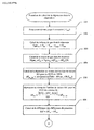
- the procedure for controlling the solenoid valve begins with phase 401 which consists in check whether the purging conditions are met. As long as the various conditions for activating the purge are not met, the algorithm remains in phase 401.
- phase 402 is activated and determines the control frequency FC of the solenoid valve 6, then in phase 403 the opening offset, noted OFF_RCO, of the solenoid valve 6 is determined as a function of the control frequency FC and of the initial collector vacuum ⁇ P res .
- a control RCO objective, noted OBJ_RCO, then an opening step, noted PAS_RCO, are determined successively during phases 404 and 405. Then, in phase 406 a test is carried out. If the RCO at the preceding calculation step is greater than the objective of calculated RCO, then phase 407 is executed otherwise it is phase 408 which is accomplished.
- the phases 407 and 408 aim to decrease or increase the RCO for controlling the solenoid valve 6, while respecting the limits of RCO, denoted RCO lim_min and RCO lim_max (physical limits of the component or limits due to diagnostic requirements). electric).
- the basic strategy of figure 5 can be modified according to figure 7 by adding a phase 409.
- the RCO is likely to be limited to the value of RCO max initialized in phase 302 and which is determined then, as we will see , in phase 514 or in phase 515.
- the procedure ends, and then, with the frequency and RCO parameters, the computer 10 generates the control signal which opens the solenoid valve 6 and a vacuum is established at l connecting hole 101.
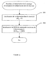
- the diagram of the process for estimating the depression in the tank then begins with the acquisition of the level of the gauge 5 in phase 501, which allows the calculation of the volume of gas in the tank 2 in phase 502 according to formula E.1.
- Phase 504 calculates, as a function of the collector depression ⁇ P coll , the depression ⁇ P can_100 at the connection orifice 101 for an RCO of 100% by means of the table of values denoted Table_DPcan_100.
- Table_DPcan_100 As this embodiment uses a solenoid valve whose flow rate, for the same collector depression, is pseudo-linear as a function of the value of the RCO, then the depression in the connection orifice 101 ⁇ P can is calculated in phase 505 by means of a proportionality rule as a function of the RCO for controlling the solenoid valve determined in phase 409 and the RCO offset determined in phase 403.
- a difference in pressures ⁇ P res - ⁇ P can exists between the ends of the connection circuit 3, which is calculated in phase 506 according to formula E.6.
- the result is stored in the variable ⁇ P.
- the invention considers that the sign of this difference, determined in phase 507, gives the direction of flow. If the sign is positive then phase 508 calculates the variation in mass ⁇ Mgaz res for a flow in the direction of the reservoir 2 towards the absorber 1 by means of interpolations in a table of values denoted Table_DM_1 as a function of the absolute value of ⁇ P . This table of values is determined by calculations using equation E.5. Then, in phase 509, the new mass of gas present in the tank 2 is deduced.
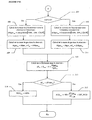
- ⁇ P res The value of ⁇ P res is compared to a vacuum threshold ⁇ Pmax res in phase 513. If the value of ⁇ P res is less than the threshold ⁇ Pmax res , then phase 514 is executed and the maximum value of 100% is given to the variable RCO max ; otherwise phase 515 is executed and it calculates the value to be given to the variable RCO max so that the application of this value implies that the depression at the level of the connection orifice 101 is equal to the value of the depression threshold ⁇ P max res . In the latter case, at the next calculation step, the RCO will be limited during phase 409 and thus, the vacuum in the tank will not exceed the value of ⁇ Pmax res .
- the method according to the invention can be applied to a vehicle equipped a ventilation valve and a pressure cator placed on the tank. Thus, it is possible to compare the value of the depression acquired by the pressure sensor with the pressure value estimated according to the process according to the invention.
- the measured depression is greater than the estimated depression then there is a plug on the air vent of the absorber.
- This plug may be due to dirt or a malfunction of Im ventilation valve, the valve is closed instead of being open, when it is supposed to be open.
Claims (8)
- Verfahren zur Regelung des Unterdrucks in einem Kraftstofftank (2) für Fahrzeuge, welcher durch die Reinigung/Entleerung eines Absorbers (1) für Kraftstoffdämpfe mittels eines elektromagnetischen Aktuators 6 erzeugt wird, der in der Reinigungs-/Entleerungsleitung (4) des Absorbers, wobei das Verfahren dadurch gekennzeichnet ist, dass es umfasst:wobei ΔPres(ti) der Schätzung der Höhe des Unterdrucks im Zeitpunkt ti isteinen Schritt der Schätzung des im Tank herrschenden Unterdrucks im offenen Regelkreis und in einem bestimmten Zeitintervall (ti), gemäß der Formel:
Patmo dem Atmosphärendruck entspricht
Mgazres(ti) eine Schätzung der Gasmasse ist, die in dem Tank vorhanden ist, abhängig von ΔPres(ti-1) und von der Bewegungsrichtung des Gases zwischen dem Tank und dem Absorber
r die Konstante des in dem Tank vorhandenen Gases ist
T die Temperatur des Gases in Kelvin ist
Vgazres(ti) dem Volumen des in dem Tank vorhandenen Gases ist. - Verfahren gemäß Anspruch 1, dadurch gekennzeichnet, dass es einen Schritt des Vergleichens der Höhe des Unterdrucks mit einem bestimmten Schwellwert umfasst, wobei,
wenn der Schwellwert überschritten ist, das Verfahren einen Schritt der Erzeugung eines Signals zur Steuerung des elektromechanischen Aktuators (6) umfasst, um die Höhe des Unterdrucks unter oder gleich dem bestimmten Schwellwert zu halten. - Verfahren gemäß Anspruch 1 oder 2, dadurch gekennzeichnet, dass die Masse des in dem Tank vorhandenen Gases definiert wird durch die Formel:
ΔMgazgen(ti) der Masse des durch Verdampfen während der Zeit Δt erzeugten Gases entspricht
ΔMgazres(ti) der Masse des Gases entspricht, welches die Verbindungsleitung während der Zeit Δt durchquert
At der Dauer des bestimmten Intervalls entspricht. - Verfahren gemäß Anspruch 3, dadurch gekennzeichnet, dass die Masse des Gases, welches die Verbindungsleitung während der Zeit Δt durchquert, definiert wird durch die Formel:
und Se einem äquivalenten Abschnitt der Verbindungsleitung zwischen dem Absorber und dem Tank entspricht
ΔPcan(ti) dem statischen Unterdruck auf Höhe der Verbindungsöffnung zwischen dem Absorber und der Verbindungsleitung entspricht, wobei dieser Unterdruck bestimmt wird durch eine Kartographie, welche von dem Druck in dem Einlasskrümmer und von mindestens einem der Parameter des Signals zur Steuerung des elektromagnetischen Aktuators abhängt. - Verfahren gemäß 3 oder 4, dadurch gekennzeichnet, dass die Formel der Masse des in dem Tank vorhandenen Gases korrigiert wird durch Abziehen eines Terms ΔMgazfuite(ti), der repräsentativ ist für die Masse des Gases welche einem Entweichen von Gas aus einem bestimmten Abschnitt Sfuite entspricht, der definiert wird durch die Formel:
- Verfahren gemäß einem der Ansprüche 1 bis 5, dadurch gekennzeichnet, dass das Volumen des in dem Tank vorhandenen Gases bestimmt wird durch die Formel:
Vcarb(ti) - εjauge dem tatsächlich in dem Tank vorhandenen Volumen an Kraftstoff entspricht, wobei dieses Volumen einer Information entspricht, die von dem Messstab für Kraftstoff herrührt, der in dem Tank montiert ist,
Vmort dem minimalen Volumen von Gas entspricht, das in dem Tank vorhanden ist. - Verfahren gemäß einem der Ansprüche 2 bis 6, dadurch gekennzeichnet, dass das Verfahren einen Schritt der Messung des in dem Tank herrschenden Unterdrucks durch einen Drucksensor umfasst, der in dem Tank oder einem mit dem Tank verbundenen Element platziert ist,
einen Schritt des Vergleichens zwischen der geschätzten Höhe des Unterdrucks und der durch den Sensor gemessenen Höhe des Unterdrucks. - Verbrennungsmotor, ausgestattet mit einem Absorber (1) für Kraftstoffdämpfe, der in Verbindung mit dem Kraftstofftank montiert ist, wobei der Motor einen Rechner umfasst, der dazu bestimmt ist, das Verfahren gemäß einem der Ansprüche 1 bis 8 zu verwirklichen.
Applications Claiming Priority (2)
| Application Number | Priority Date | Filing Date | Title |
|---|---|---|---|
| FR0116531 | 2001-12-20 | ||
| FR0116531A FR2833999B1 (fr) | 2001-12-20 | 2001-12-20 | Procede de regulation de la depression dans un reservoir a carburant pour automobile generee par la purge de l'absorbeur de vapeurs de carburant |
Publications (2)
| Publication Number | Publication Date |
|---|---|
| EP1321652A1 EP1321652A1 (de) | 2003-06-25 |
| EP1321652B1 true EP1321652B1 (de) | 2004-10-13 |
Family
ID=8870736
Family Applications (1)
| Application Number | Title | Priority Date | Filing Date |
|---|---|---|---|
| EP20020293193 Expired - Fee Related EP1321652B1 (de) | 2001-12-20 | 2002-12-20 | Verfahren zur Regelung des Kraftstofftankunterdrucks eines Fahrzeugs |
Country Status (3)
| Country | Link |
|---|---|
| EP (1) | EP1321652B1 (de) |
| DE (1) | DE60201570T2 (de) |
| FR (1) | FR2833999B1 (de) |
Families Citing this family (1)
| Publication number | Priority date | Publication date | Assignee | Title |
|---|---|---|---|---|
| DE102019215472B4 (de) * | 2019-10-09 | 2023-05-11 | Vitesco Technologies GmbH | Verfahren sowie Vorrichtung zur Ermittlung des Durchflusses durch ein Taktventil |
Family Cites Families (5)
| Publication number | Priority date | Publication date | Assignee | Title |
|---|---|---|---|---|
| US5237979A (en) * | 1991-09-02 | 1993-08-24 | Toyota Jidosha Kabushiki Kaisha | Evaporative fuel control apparatus of internal combustion engine |
| DE4321694A1 (de) * | 1993-06-30 | 1995-01-12 | Bosch Gmbh Robert | Verfahren zur Tankentlüftung |
| JP3689126B2 (ja) * | 1994-03-18 | 2005-08-31 | 本田技研工業株式会社 | 内燃機関の蒸発燃料制御装置 |
| US6276193B1 (en) * | 2000-08-10 | 2001-08-21 | Eaton Corporation | Detecting vapor leakage in a motor vehicle fuel system |
| IT1321093B1 (it) * | 2000-11-24 | 2003-12-30 | Dayco Europe Srl | Dispositivo e metodo per il monitoraggio del rapporto carburante/ariadella miscela di aria e vapori alimentati in uscita da un accumulatore |
-
2001
- 2001-12-20 FR FR0116531A patent/FR2833999B1/fr not_active Expired - Fee Related
-
2002
- 2002-12-20 EP EP20020293193 patent/EP1321652B1/de not_active Expired - Fee Related
- 2002-12-20 DE DE2002601570 patent/DE60201570T2/de not_active Expired - Lifetime
Also Published As
| Publication number | Publication date |
|---|---|
| DE60201570D1 (de) | 2004-11-18 |
| FR2833999B1 (fr) | 2004-01-30 |
| EP1321652A1 (de) | 2003-06-25 |
| FR2833999A1 (fr) | 2003-06-27 |
| DE60201570T2 (de) | 2005-03-31 |
Similar Documents
| Publication | Publication Date | Title |
|---|---|---|
| FR2761307A1 (fr) | Procede de verification du bon fonctionnement d'un dispositif d'aeration du reservoir d'un vehicule | |
| FR2851610A1 (fr) | Procede et dispositif de gestion d'un moteur a combustion interne | |
| WO2018002550A1 (fr) | Procédé de contrôle d'une mesure de pression dans un réservoir de carburant | |
| FR2704648A1 (fr) | Procédé et dispositif de diagnostic de ventilation d'un réservoir de véhicule automobile. | |
| FR2874237A1 (fr) | Procede et dispositif de gestion d'un moteur a combustion interne | |
| FR2734213A1 (fr) | Procede de diagnostic de l'etancheite d'un systeme de ventilation de reservoir | |
| FR2688545A1 (fr) | Systeme pour commander un moteur a combustion interne. | |
| FR2881179A1 (fr) | Procede pour commander une soupape de degazage du reservoir d'un vehicule a moteur au cours d'une verification d'etancheite | |
| WO2019170973A1 (fr) | Détection de fuite dans un dispositif d'évaporation des vapeurs d'un carburant stocké dans un réservoir d'un moteur thermique de véhicule | |
| WO2011128041A1 (fr) | Procede et dispositif de diagnostic de vanne de purge pour vehicule a motorisation hybride | |
| EP1321652B1 (de) | Verfahren zur Regelung des Kraftstofftankunterdrucks eines Fahrzeugs | |
| WO1999043939A1 (fr) | Procede et dispositif d'autoadaptation rapide de richesse pour moteur a combustion interne | |
| FR2817915A1 (fr) | Procede et appareil de commande et de regulation pour la mise en oeuvre d'un moteur a combustion interne | |
| EP2427643A1 (de) | Verfahren und vorrichtung zur diagnose des betriebszustands einer kraftstoffzufuhranlage eines kraftfahrzeugbrennkraftmotors | |
| EP3052781B1 (de) | Verfahren zur fehlerdiagnose eines ladeluftkühlers und zugehöriges kraftwerk | |
| FR3044612A1 (fr) | Controle de la depressurisation d'un reservoire de carburant d'un vehicule automobile | |
| WO2004085811A1 (fr) | Mesure de la pression ambiante dans un moteur turbocompresse | |
| WO1996004473A1 (fr) | Procede de controle du bon fonctionnement de l'assistance en air d'un injecteur de carburant pour moteur a combustion interne et dispositif correspondant | |
| FR3111665A1 (fr) | Procede d’estimation d’une pression des gaz d’echappement pour un moteur a combustion interne | |
| WO2017216442A1 (fr) | Procédé de détection de fuite dans un système de recyclage des vapeurs de carburant | |
| EP3006716B1 (de) | Verfahren zur steuerung eines verbrennungsmotors, der mit einer gasaufbereitungsvorrichtung ausgestattet ist | |
| FR2990175A1 (fr) | Procede de demande de demarrage ou de maintien en fonctionnement du moteur thermique d'un vehicule hybride en vue d'une purge du canister | |
| FR3076903A1 (fr) | Procédé de détermination de l'état thermodynamique du carburant dans un système de carburant | |
| KR102428065B1 (ko) | 능동형 퍼지 수행 방법 및 능동형 퍼지 시스템 | |
| WO2022161859A1 (fr) | Dispositif et procede de purge d'un flux de gaz charge en vapeurs d'hydrocarbures |
Legal Events
| Date | Code | Title | Description |
|---|---|---|---|
| PUAI | Public reference made under article 153(3) epc to a published international application that has entered the european phase |
Free format text: ORIGINAL CODE: 0009012 |
|
| AK | Designated contracting states |
Designated state(s): AT BE BG CH CY CZ DE DK EE ES FI FR GB GR IE IT LI LU MC NL PT SE SI SK TR |
|
| AX | Request for extension of the european patent |
Extension state: AL LT LV MK RO |
|
| 17P | Request for examination filed |
Effective date: 20031209 |
|
| AKX | Designation fees paid |
Designated state(s): DE GB |
|
| GRAP | Despatch of communication of intention to grant a patent |
Free format text: ORIGINAL CODE: EPIDOSNIGR1 |
|
| GRAS | Grant fee paid |
Free format text: ORIGINAL CODE: EPIDOSNIGR3 |
|
| GRAA | (expected) grant |
Free format text: ORIGINAL CODE: 0009210 |
|
| AK | Designated contracting states |
Kind code of ref document: B1 Designated state(s): DE GB |
|
| REG | Reference to a national code |
Ref country code: GB Ref legal event code: FG4D Free format text: NOT ENGLISH |
|
| REG | Reference to a national code |
Ref country code: IE Ref legal event code: FG4D Free format text: FRENCH |
|
| REF | Corresponds to: |
Ref document number: 60201570 Country of ref document: DE Date of ref document: 20041118 Kind code of ref document: P |
|
| GBT | Gb: translation of ep patent filed (gb section 77(6)(a)/1977) |
Effective date: 20041215 |
|
| REG | Reference to a national code |
Ref country code: IE Ref legal event code: FD4D |
|
| PLBE | No opposition filed within time limit |
Free format text: ORIGINAL CODE: 0009261 |
|
| STAA | Information on the status of an ep patent application or granted ep patent |
Free format text: STATUS: NO OPPOSITION FILED WITHIN TIME LIMIT |
|
| 26N | No opposition filed |
Effective date: 20050714 |
|
| PGFP | Annual fee paid to national office [announced via postgrant information from national office to epo] |
Ref country code: DE Payment date: 20161213 Year of fee payment: 15 Ref country code: GB Payment date: 20161222 Year of fee payment: 15 |
|
| REG | Reference to a national code |
Ref country code: DE Ref legal event code: R119 Ref document number: 60201570 Country of ref document: DE |
|
| GBPC | Gb: european patent ceased through non-payment of renewal fee |
Effective date: 20171220 |
|
| PG25 | Lapsed in a contracting state [announced via postgrant information from national office to epo] |
Ref country code: DE Free format text: LAPSE BECAUSE OF NON-PAYMENT OF DUE FEES Effective date: 20180703 |
|
| PG25 | Lapsed in a contracting state [announced via postgrant information from national office to epo] |
Ref country code: GB Free format text: LAPSE BECAUSE OF NON-PAYMENT OF DUE FEES Effective date: 20171220 |