EP1321633A1 - Internal combustion engine - Google Patents
Internal combustion engine Download PDFInfo
- Publication number
- EP1321633A1 EP1321633A1 EP01970193A EP01970193A EP1321633A1 EP 1321633 A1 EP1321633 A1 EP 1321633A1 EP 01970193 A EP01970193 A EP 01970193A EP 01970193 A EP01970193 A EP 01970193A EP 1321633 A1 EP1321633 A1 EP 1321633A1
- Authority
- EP
- European Patent Office
- Prior art keywords
- exhaust
- intake valve
- intake
- valve
- cylinder head
- Prior art date
- Legal status (The legal status is an assumption and is not a legal conclusion. Google has not performed a legal analysis and makes no representation as to the accuracy of the status listed.)
- Withdrawn
Links
- 238000002485 combustion reaction Methods 0.000 title claims abstract description 58
- 239000007789 gas Substances 0.000 abstract description 31
- 230000001965 increasing effect Effects 0.000 abstract description 8
- 239000002918 waste heat Substances 0.000 abstract description 8
- 230000007423 decrease Effects 0.000 abstract description 7
- 238000011084 recovery Methods 0.000 description 7
- 238000010586 diagram Methods 0.000 description 5
- 230000006835 compression Effects 0.000 description 3
- 238000007906 compression Methods 0.000 description 3
- 230000006866 deterioration Effects 0.000 description 2
- 239000000446 fuel Substances 0.000 description 2
- 239000007791 liquid phase Substances 0.000 description 2
- 230000004048 modification Effects 0.000 description 2
- 238000012986 modification Methods 0.000 description 2
- 239000000956 alloy Substances 0.000 description 1
- 229910045601 alloy Inorganic materials 0.000 description 1
- 238000000889 atomisation Methods 0.000 description 1
- 230000015556 catabolic process Effects 0.000 description 1
- 238000001816 cooling Methods 0.000 description 1
- 230000003247 decreasing effect Effects 0.000 description 1
- 238000006731 degradation reaction Methods 0.000 description 1
- 230000000593 degrading effect Effects 0.000 description 1
- 230000000694 effects Effects 0.000 description 1
- 230000002708 enhancing effect Effects 0.000 description 1
- 238000010438 heat treatment Methods 0.000 description 1
- 239000012212 insulator Substances 0.000 description 1
- 230000014759 maintenance of location Effects 0.000 description 1
- 230000002093 peripheral effect Effects 0.000 description 1
- 230000001737 promoting effect Effects 0.000 description 1
- 238000007789 sealing Methods 0.000 description 1
- 238000011144 upstream manufacturing Methods 0.000 description 1
Images





Classifications
-
- F—MECHANICAL ENGINEERING; LIGHTING; HEATING; WEAPONS; BLASTING
- F01—MACHINES OR ENGINES IN GENERAL; ENGINE PLANTS IN GENERAL; STEAM ENGINES
- F01L—CYCLICALLY OPERATING VALVES FOR MACHINES OR ENGINES
- F01L1/00—Valve-gear or valve arrangements, e.g. lift-valve gear
- F01L1/28—Valve-gear or valve arrangements, e.g. lift-valve gear characterised by the provision of coaxial valves; characterised by the provision of valves co-operating with both intake and exhaust ports
- F01L1/285—Coaxial intake and exhaust valves
-
- F—MECHANICAL ENGINEERING; LIGHTING; HEATING; WEAPONS; BLASTING
- F01—MACHINES OR ENGINES IN GENERAL; ENGINE PLANTS IN GENERAL; STEAM ENGINES
- F01L—CYCLICALLY OPERATING VALVES FOR MACHINES OR ENGINES
- F01L1/00—Valve-gear or valve arrangements, e.g. lift-valve gear
- F01L1/28—Valve-gear or valve arrangements, e.g. lift-valve gear characterised by the provision of coaxial valves; characterised by the provision of valves co-operating with both intake and exhaust ports
-
- F—MECHANICAL ENGINEERING; LIGHTING; HEATING; WEAPONS; BLASTING
- F01—MACHINES OR ENGINES IN GENERAL; ENGINE PLANTS IN GENERAL; STEAM ENGINES
- F01L—CYCLICALLY OPERATING VALVES FOR MACHINES OR ENGINES
- F01L1/00—Valve-gear or valve arrangements, e.g. lift-valve gear
- F01L1/46—Component parts, details, or accessories, not provided for in preceding subgroups
- F01L1/462—Valve return spring arrangements
-
- F—MECHANICAL ENGINEERING; LIGHTING; HEATING; WEAPONS; BLASTING
- F01—MACHINES OR ENGINES IN GENERAL; ENGINE PLANTS IN GENERAL; STEAM ENGINES
- F01L—CYCLICALLY OPERATING VALVES FOR MACHINES OR ENGINES
- F01L3/00—Lift-valve, i.e. cut-off apparatus with closure members having at least a component of their opening and closing motion perpendicular to the closing faces; Parts or accessories thereof
- F01L3/12—Cooling of valves
-
- F—MECHANICAL ENGINEERING; LIGHTING; HEATING; WEAPONS; BLASTING
- F02—COMBUSTION ENGINES; HOT-GAS OR COMBUSTION-PRODUCT ENGINE PLANTS
- F02G—HOT GAS OR COMBUSTION-PRODUCT POSITIVE-DISPLACEMENT ENGINE PLANTS; USE OF WASTE HEAT OF COMBUSTION ENGINES; NOT OTHERWISE PROVIDED FOR
- F02G5/00—Profiting from waste heat of combustion engines, not otherwise provided for
- F02G5/02—Profiting from waste heat of exhaust gases
-
- Y—GENERAL TAGGING OF NEW TECHNOLOGICAL DEVELOPMENTS; GENERAL TAGGING OF CROSS-SECTIONAL TECHNOLOGIES SPANNING OVER SEVERAL SECTIONS OF THE IPC; TECHNICAL SUBJECTS COVERED BY FORMER USPC CROSS-REFERENCE ART COLLECTIONS [XRACs] AND DIGESTS
- Y02—TECHNOLOGIES OR APPLICATIONS FOR MITIGATION OR ADAPTATION AGAINST CLIMATE CHANGE
- Y02T—CLIMATE CHANGE MITIGATION TECHNOLOGIES RELATED TO TRANSPORTATION
- Y02T10/00—Road transport of goods or passengers
- Y02T10/10—Internal combustion engine [ICE] based vehicles
- Y02T10/12—Improving ICE efficiencies
Definitions
- the present invention relates to an internal combustion engine in which an intake valve and an exhaust valve are coaxially disposed.
- a Panhard internal combustion engine in which an intake valve and an exhaust valve are coaxially disposed, is disclosed in FIG. 3.27 on page 82 of 'History of the Internal Combustion Engine' (K. Tomizuka, Sanei-shobo Publishing Co., Ltd.)
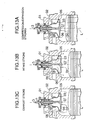
- FIG. 13A to FIG. 13C are schematic diagrams of the structure of the Panhard internal combustion engine.
- a radially outer exhaust valve 03 and a radially inner intake valve 04 are coaxially disposed on a cylinder axis L of a cylinder block 02 joined to a cylinder head 01, the exhaust valve 03 being capable of being seated on an exhaust valve hole 05 formed in the cylinder block 02, and the intake valve 04 being capable of being seated on an intake valve hole 06 formed in the exhaust valve 03.
- both the exhaust valve 03 and the intake valve 04 are closed, thus cutting off a combustion chamber 07 from an exhaust port 08 and an intake port 09.
- the intake valve 04 descends to open the intake valve hole 06, thus providing communication between the combustion chamber 07 and the intake port 09.
- both the exhaust valve 03 and the intake valve 04 descend to open the exhaust valve hole 05, thus providing communication between the combustion chamber 07 and the exhaust port 08.
- the exhaust port 08 connected to the exhaust valve hole 05 is formed directly in the cylinder head 01 and the cylinder block 02, which have a large heat capacity, the exhaust gas coming out of the combustion chamber 07 is deprived of heat by the cylinder head 01 and the cylinder block 02 and its temperature tends to decrease. Because of this, in the case where a heat exchanger is disposed in the exhaust port 08 or downstream thereof, the temperature of the exhaust gas flowing into the heat exchanger is low, thus causing the problem that the efficiency of thermal energy recovery deteriorates.
- the present invention has been accomplished in view of the above-mentioned circumstances, and it is an object of the present invention to provide an internal combustion engine that can ensure that an intake valve opening has sufficient area and that can utilize effectively exhaust gas thermal energy.
- an internal combustion engine that includes a cylinder head, a combustion chamber facing the cylinder head, an intake port formed in the cylinder head, an intake valve hole formed in the cylinder head and providing communication between the intake port and the combustion chamber, a hollow intake valve supported in the cylinder head and opening and closing the intake valve hole, an exhaust passage formed axially within the intake valve, an exhaust valve hole formed in the intake valve and providing communication between the exhaust passage and the combustion chamber, an exhaust valve coaxially supported within the intake valve and opening and closing the exhaust valve hole, and an exhaust port formed in the cylinder head and communicating with the exhaust passage.
- the exhaust valve is coaxially housed within the hollow intake valve that opens and closes the intake valve hole of the cylinder head and the exhaust valve opens and closes the exhaust valve hole formed in the intake valve, the intake valve hole alone can be opened by making the intake valve and the exhaust valve descend as a unit, and the exhaust valve alone can be opened by making the exhaust valve descend independently.
- the diameter of the radially outwardly disposed intake valve hole so that it is larger than the diameter of the radially inwardly disposed exhaust valve hole and so that it is nearly the same as the inner diameter of the combustion chamber, a large opening area can be ensured for the intake valve, and the intake charging efficiency can be increased compared with a conventional internal combustion engine in which an intake valve and an exhaust valve are disposed on separate axes, or the Panhard internal combustion engine in which the radially outer exhaust valve and the radially inner intake valve are disposed coaxially. As a result, the lift of the intake valve required to ensure a predetermined opening area can be decreased, and the driving force for the intake valve can be reduced.
- the exhaust gas that has just come out of the combustion chamber is guided into the exhaust port through the exhaust passage formed within the hollow intake valve, which has a small heat capacity, without making direct contact with the cylinder head, which has a large heat capacity, the decrease in temperature of the exhaust gas can be minimized, thereby utilizing waste heat effectively.
- an internal combustion engine that further includes a heat exchanger disposed in the exhaust port.
- the heat exchanger is disposed in the exhaust port connected to the downstream side of the exhaust passage formed within the hollow intake valve, which has a small heat capacity, high temperature exhaust gas can be supplied to the heat exchanger, thereby maximizing the efficiency of waste heat recovery.
- An evaporator 39 of embodiments corresponds to the heat exchanger of the present invention.
- FIG. 1 to FIG. 8 illustrate a first embodiment of the present invention
- FIG. 1 is a vertical cross section of a cylinder head part of an internal combustion engine
- FIG. 2 is a cross section along line 2-2 in FIG. 1
- FIG. 3 is a cross section along line 3-3 in FIG. 1
- FIG. 4 is a cross section along line 4-4 in FIG. 1
- FIG. 5 is a view from line 5-5 in FIG. 1
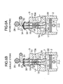
- FIG. 6A and FIG. 6B are diagrams for explaining the operation of the intake stroke and the exhaust stroke respectively
- FIG. 7A is a diagram for explaining the opening area of a conventional intake valve
- FIG. 7B is a diagram for explaining the opening area of an intake valve in this embodiment
- FIG. 8 is a graph showing the relationship between the lift and the opening area of the intake valve;
- FIG. 9 is a vertical cross section of a cylinder head part of an internal combustion engine related to a second embodiment;
- FIG. 10 is a vertical cross section of a cylinder head part of an internal combustion engine related to a third embodiment;
- FIG. 11 and FIG. 12 illustrate a fourth embodiment;
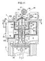
- FIG. 11 is a vertical cross section of a cylinder head part of an internal combustion engine;
- FIG. 12 is a cross section along line 12-12 in FIG. 11;
- FIG. 13A to FIG. 13C are diagrams for explaining the structure and operation of a Panhard internal combustion engine.
- a single-cylinder four-stroke internal combustion engine 1 includes a cylinder block 2 and a cylinder head 3 joined to the upper face of the cylinder block 2, and a combustion chamber 5 is formed between the lower face of the cylinder head 3 and the upper face of a piston 4 that is slidably fitted in a cylinder bore 2a.
- a pair of spark plugs 6 are screwed into the cylinder head 3, and their tips face the combustion chamber 5.
- a circular intake valve hole 7 that is coaxial with a cylinder axis L is formed in the lower face of the cylinder head 3, and an intake port 8 extending from the intake valve hole 7 runs through the interior of the cylinder head 3, and opens on one side 3a of the cylinder head 3.
- An intake valve 9 includes a stem 10 and a head 11, the stem 10 being in the form of a tube and having a circular cross-section, and the head 11 extending radially outward from the lower end of the stem 10.
- the upper face of the outer peripheral part of the head 11 faces the intake valve hole 7 of the cylinder head 3 and can be seated thereon.
- a pair of upper and lower intake valve guides 12, 13 supporting the stem 10 of the intake valve 9 in a vertically slidable manner, and formed on the stem 10 are a plurality of (for example, four) through holes 10a.
- An exhaust valve guide 17 is supported within the stem 10 of the intake valve 9 coaxially with the cylinder axis L via an upper support member 15 and lower support members 16.
- the upper support member 15 is an annular member and is fixed to the inner periphery of the stem 10 and the outer periphery of the exhaust valve guide 17.
- the lower support members 16 are a plurality of (for example, four) rodlike members, are disposed radially around the cylinder axis L, and provide connections between the inner periphery of the stem 10 and the outer periphery of the exhaust valve guide 17.
- An exhaust valve 18 includes a stem 19 and a head 20; the stem 19 is slidably supported by the exhaust valve guide 17, and the head 20 can be seated on an exhaust valve hole 22 at the lower end of an exhaust passage 21 formed within the intake valve 9.
- the combustion chamber 5 can therefore communicate with the exhaust port 14 via the exhaust valve hole 22, the exhaust passage 21 formed within the stem 10 of the intake valve 9, spaces formed between the four lower support members 16, and the four through holes 10a.
- the exhaust gas within the exhaust passage 21 is blocked from leaking upward by the upper support member 15.
- a valve operating mechanism 25 disposed in an upper part of the cylinder head 3 includes a camshaft 26 rotatable in association with a crank shaft (not illustrated), a pair of intake cams 27 fixed to the camshaft 26, an exhaust cam 28 fixed to the camshaft 26 between the two intake cams 27, a pair of intake rocker arms 30 pivotably supported on a rocker arm shaft 29 and driven by the intake cams 27, and an exhaust rocker arm 31 pivotably supported on the rocker arm shaft 29 and driven by the exhaust cams 28.
- a plurality of (for example, four) openings 10b are formed at positions above the upper support member 15 on the stem 10 of the intake valve 9, and four lower spring seats 32 passing loosely through these openings 10b and passing through the upper intake valve guide 12 are supported on the upper face of the cylinder head 3.
- An annular first upper spring seat 33 is fitted around the upper end of the stem 10; furthermore, an annular cam follower 34 is fixedly fitted around the upper end of the stem 10, and an intake valve spring 35 is provided in a compressed state between the lower spring seats 32 and the first upper spring seat 33.
- a second upper spring seat 36 that can pass through the interior of the annular cam follower 34 is fixed to the upper end of the stem 19 of the exhaust valve 18, and an exhaust valve spring 37 is provided in a compressed state between the second upper spring seat 36 and the lower spring seats 32.
- the intake valve spring 35 biases the intake valve 9 in a valve closing direction so as to seat the head 11 thereof on the intake valve hole 7, and the exhaust valve spring 37 biases the exhaust valve 18 in a valve closing direction so as to seat the head 20 thereof on the exhaust valve hole 22.
- the exhaust cam 28 pushes the upper end of the stem 19 via the exhaust rocker arm 31 so as to push down the exhaust valve 18 against the exhaust valve spring 37, the head 20 of the exhaust valve 18 becomes detached from the exhaust valve hole 22, and as a result the combustion chamber 5 is made to communicate with the exhaust port 14 via the exhaust valve hole 22, the exhaust passage 21, and the through holes 10a.
- the intake stroke, the compression stroke, the expansion stroke, and the exhaust stroke can be carried out sequentially with rotation of the camshaft 26.
- FIG. 7A and FIG. 78 schematically illustrate a conventional case in which two intake valve holes 7 and two exhaust valve holes 22 are disposed on separate axes, and the embodiment in which one intake valve hole 7 and one exhaust valve hole 22 are coaxially disposed.
- the diameter of each of the conventional exhaust valve holes 22 is D and the diameter of the intake valve hole 7 in the embodiment is 2D
- the total of the simple opening areas of the two conventional intake valve holes 7 is ⁇ D 2 /2 based on a calculation using the hole diameter
- the simple opening area of the intake valve hole 7 in the embodiment is ⁇ D 2 , thus making it possible to ensure that the simple opening area in the embodiment is twice that of the conventional case.
- the diameter of the intake valve hole 7 in the embodiment is slightly smaller than 2D
- the simple opening area is slightly less than twice that of the conventional case.
- FIG. 8 shows a comparison between the conventional case and the embodiment with respect to the effective opening area calculated from the lift of the intake valve 9 and the actual flow rate of the intake valve hole 7.
- the lift of the intake valve 9 in the conventional case is H whereas the lift of the intake valve in the embodiment is only H', which is approximately one half of H.
- the intake valve 9 is disposed radially outside the exhaust valve 18, it is possible to ensure that the intake valve hole 7 has a large opening area compared with the conventional internal combustion engine in which the intake valve and the exhaust valve are disposed on separate axes and also compared with the Panhard internal combustion engine (see FIG. 13A to FIG. 13C) in which the intake valve is disposed radially inside the exhaust valve.
- the Panhard internal combustion engine see FIG. 13A to FIG. 13C
- the high temperature exhaust gas that has just come out of the combustion chamber 5 is guided to the exhaust port 14 of the cylinder head 3 via the exhaust passage 21 formed inside the stem 10 of the intake valve 9 without making direct contact with the cylinder head 3, which has a large heat capacity. Since the stem 10 forming the exhaust passage 21 is thin, has a very small heat capacity, and is only supported in the cylinder head 3 by the intake valve guides 12, 13, which have a small area, it is possible to effectively prevent the exhaust gas from being deprived of heat by the cylinder head 3.
- valve operating mechanism 25 can be arranged in a compact manner immediately above the cylinder head 3, it is possible to easily secure a space for other members to be arranged around the periphery of the cylinder head 3.
- an evaporator 39 is supported, via a heat insulator 38, in a recess 3c formed on a side 3b of a cylinder head 3.
- the evaporator 39 which functions as a heat exchanger, is used in, for example, a Rankine cycle system for converting the thermal energy of exhaust gas of the internal combustion engine 1 into mechanical energy; heat exchange is carried out between the exhaust gas and a liquid phase working medium supplied through an inlet 39a, and vapor generated by heating the liquid phase working medium is discharged through an outlet 39b.
- FIG. 10 A third embodiment of the present invention is now explained by reference to FIG. 10.
- the third embodiment is a modification of the second embodiment, and an intake valve 9 and an exhaust valve 18 are inclined, relative to a cylinder axis L, toward an intake port 8 of a cylinder head 3.
- a space can be secured on an exhaust port 14 side of the cylinder head 3, and it is therefore possible to increase the size and capacity of the evaporator 39 by utilizing this space, or reduce the overall size of the cylinder head 3 by using the evaporator 39 with an unchanged size.
- making the evaporator 39 closer to the vicinity of the combustion chamber 5 makes it possible to recover waste heat in a state in which the exhaust heat is maintained at high temperature, thereby increasing the recovery efficiency.
- FIG. 11 A fourth embodiment of the present invention is now explained by reference to FIG. 11 and FIG. 12.
- the fourth embodiment is a modification of the second embodiment, and an evaporator 39 is made in an annular form and disposed so as to surround an intake valve 9, thereby greatly increasing the capacity of the evaporator 39.
- the cylinder head 3 can be divided into two members, that is, a lower cylinder head 40 and an upper cylinder head 41.
- the embodiments illustrate a single-cylinder internal combustion engine 1, but the present invention can also be applied to a multicylinder internal combustion engine.
- the embodiments illustrate an evaporator 39 of a Rankine cycle system as a heat exchanger, but it is possible to employ any type of heat exchanger.
- the present invention can be applied to an internal combustion engine, which is represented by a gasoline engine, but its application is not limited.
Landscapes
- Engineering & Computer Science (AREA)
- Mechanical Engineering (AREA)
- General Engineering & Computer Science (AREA)
- Chemical & Material Sciences (AREA)
- Combustion & Propulsion (AREA)
- Cylinder Crankcases Of Internal Combustion Engines (AREA)
- Valve-Gear Or Valve Arrangements (AREA)
Abstract
Description
Claims (2)
- An internal combustion engine comprising:a cylinder head (3);a combustion chamber (5) facing the cylinder head (3);an intake port (8) formed in the cylinder head (3);an intake valve hole (7) formed in the cylinder head (3) and providing communication between the intake port (8) and the combustion chamber (5);an intake valve (9) supported in the cylinder head (3) and opening and closing the intake valve hole (7);an exhaust passage (21) formed axially within the intake valve (9);an exhaust valve hole (22) formed in the intake valve (9) and providing communication between the exhaust passage (21) and the combustion chamber (5);an exhaust valve (18) coaxially supported within the intake valve (9) and opening and closing the exhaust valve hole (22); andan exhaust port (14) formed in the cylinder head (3) and communicating with the exhaust passage (21).
- The internal combustion engine according to Claim 1 further comprising a heat exchanger (39) disposed in the exhaust port (14).
Applications Claiming Priority (3)
| Application Number | Priority Date | Filing Date | Title |
|---|---|---|---|
| JP2000295423A JP2002097907A (en) | 2000-09-25 | 2000-09-25 | Internal combustion engine |
| JP2000295423 | 2000-09-25 | ||
| PCT/JP2001/008260 WO2002025069A1 (en) | 2000-09-25 | 2001-09-21 | Internal combustion engine |
Publications (2)
| Publication Number | Publication Date |
|---|---|
| EP1321633A1 true EP1321633A1 (en) | 2003-06-25 |
| EP1321633A4 EP1321633A4 (en) | 2004-09-22 |
Family
ID=18777849
Family Applications (1)
| Application Number | Title | Priority Date | Filing Date |
|---|---|---|---|
| EP01970193A Withdrawn EP1321633A4 (en) | 2000-09-25 | 2001-09-21 | Internal combustion engine |
Country Status (4)
| Country | Link |
|---|---|
| US (1) | US6971344B2 (en) |
| EP (1) | EP1321633A4 (en) |
| JP (1) | JP2002097907A (en) |
| WO (1) | WO2002025069A1 (en) |
Cited By (1)
| Publication number | Priority date | Publication date | Assignee | Title |
|---|---|---|---|---|
| FR2894629A1 (en) * | 2005-12-13 | 2007-06-15 | Nicolas Casse | Cylinder head with optimized fluid filling, for engine, pump or compressor, has two independent, coaxial, piston type valves, displaced by action of camshaft(s) via four pawls |
Families Citing this family (11)
| Publication number | Priority date | Publication date | Assignee | Title |
|---|---|---|---|---|
| JP4556771B2 (en) * | 2005-05-27 | 2010-10-06 | 三菱自動車工業株式会社 | Engine combustion chamber structure |
| US8109097B2 (en) * | 2007-03-07 | 2012-02-07 | Thermal Power Recovery, Llc | High efficiency dual cycle internal combustion engine with steam power recovered from waste heat |
| US20090241870A1 (en) * | 2008-04-01 | 2009-10-01 | Ralph Moore | Variable intake valve assembly for internal combustion engine |
| DK2151569T3 (en) * | 2008-08-06 | 2012-10-29 | Waertsilae Switzerland Ltd | Device for extracting an exhaust gas partial flow and combustion engine with this device |
| EP2187104B1 (en) * | 2008-11-18 | 2011-12-21 | Sauer-Danfoss ApS | Fluid distribution valve |
| CZ303732B6 (en) * | 2011-05-03 | 2013-04-10 | Knob Engines S.R.O. | Cylinder head with ring-shaped valve for internal combustion engine |
| JP2016223303A (en) * | 2015-05-27 | 2016-12-28 | トヨタ自動車株式会社 | Internal combustion engine |
| CN107023340B (en) * | 2017-05-23 | 2023-02-28 | 湖北科技学院 | Automobile engine |
| US12059963B2 (en) * | 2021-07-02 | 2024-08-13 | Universal Power & Pneumatics, Llc | Modular charging and power system |
| US12253177B2 (en) * | 2023-01-17 | 2025-03-18 | Uri Kaniel | Coaxial valve system |
| GB2632184A (en) * | 2023-07-27 | 2025-01-29 | Wang Gang | Concentric circular valve train valve mechanism for internal combustion engine |
Family Cites Families (16)
| Publication number | Priority date | Publication date | Assignee | Title |
|---|---|---|---|---|
| US3015323A (en) * | 1957-06-19 | 1962-01-02 | Ingenieurbureau D Ing Alfred J | Four-stroke internal combustion engine |
| JPS56156407A (en) * | 1980-05-02 | 1981-12-03 | Matsushita Electric Ind Co Ltd | Pankine cycle device for automobile |
| DE3600067A1 (en) * | 1986-01-03 | 1987-07-09 | Juergen Schaefler | Inlet valve and exhaust valve, especially for internal combustion engines |
| DE3725049A1 (en) * | 1987-07-29 | 1988-08-18 | Maass Erwin Dipl Ing Fh | Internal combustion engines with coaxial, concentric valve arrangement |
| US4893592A (en) * | 1988-11-07 | 1990-01-16 | Avelino Falero | Combustion chamber for an internal combustion engine |
| FR2646877A1 (en) * | 1989-05-10 | 1990-11-16 | Noel Armand | Cylinder head with movable end for 4-stroke engines |
| US4894995A (en) | 1989-05-22 | 1990-01-23 | Lawrence LaSota | Combined internal combustion and hot gas engine |
| DE4002442A1 (en) * | 1990-01-27 | 1991-08-01 | Roland Schneider | Cylinder head for IC engine - uses hollow inlet valve containing outlet valve on common axis |
| DE4041724A1 (en) * | 1990-12-24 | 1992-06-25 | Emanuele Gatto | Valve arrangement for twin spark engine system - has combination of concentric inner and outer valves |
| FR2710106B1 (en) * | 1993-09-13 | 1995-12-08 | Melchior Jean F | IMPROVEMENT IN INTERNAL COMBUSTION ENGINES |
| DE4439042A1 (en) * | 1994-11-02 | 1995-03-23 | Viktor Hammermeister | Coaxial valve system |
| DE19523304A1 (en) * | 1995-06-27 | 1997-01-02 | Traugott Horsch | Two=stroke reciprocating IC engine |
| GB2315519A (en) * | 1996-07-22 | 1998-02-04 | Martyn Shane Finney | Coaxial lift valves, eg for i.c.engines |
| DE19718710C2 (en) * | 1997-05-02 | 2001-02-15 | Lazar Lazic | Internal combustion engine with double valve |
| JP2000073753A (en) | 1998-09-01 | 2000-03-07 | Nissan Motor Co Ltd | Waste heat recovery device for internal combustion engine |
| CA2264186A1 (en) | 1999-03-03 | 2000-09-03 | Easton Bennett | Heat exchanger for a motor vehicle exhaust |
-
2000
- 2000-09-25 JP JP2000295423A patent/JP2002097907A/en active Pending
-
2001
- 2001-09-21 EP EP01970193A patent/EP1321633A4/en not_active Withdrawn
- 2001-09-21 US US10/380,998 patent/US6971344B2/en not_active Expired - Fee Related
- 2001-09-21 WO PCT/JP2001/008260 patent/WO2002025069A1/en not_active Ceased
Cited By (1)
| Publication number | Priority date | Publication date | Assignee | Title |
|---|---|---|---|---|
| FR2894629A1 (en) * | 2005-12-13 | 2007-06-15 | Nicolas Casse | Cylinder head with optimized fluid filling, for engine, pump or compressor, has two independent, coaxial, piston type valves, displaced by action of camshaft(s) via four pawls |
Also Published As
| Publication number | Publication date |
|---|---|
| US6971344B2 (en) | 2005-12-06 |
| JP2002097907A (en) | 2002-04-05 |
| WO2002025069A1 (en) | 2002-03-28 |
| US20040031454A1 (en) | 2004-02-19 |
| EP1321633A4 (en) | 2004-09-22 |
Similar Documents
| Publication | Publication Date | Title |
|---|---|---|
| US6293242B1 (en) | Rotary valve system | |
| US6971344B2 (en) | Internal combustion engine | |
| US5931131A (en) | Valve cover assembly having an integrated heat exchanger for cooling exhaust gases | |
| TWI524002B (en) | Engines and method for operating an internal combustion engine having a reciprocating piston operably disposed in a cylindrical bore of a sleeve valve | |
| US8459227B2 (en) | Sliding valve aspiration | |
| US8776756B2 (en) | Sliding valve aspiration | |
| US6546902B1 (en) | Intake and exhaust valve system | |
| US5664531A (en) | Device for adjusting valve duration using external air supply | |
| EP0808418B1 (en) | Cylinder head for an internal combustion engine | |
| JP4119281B2 (en) | Engine exhaust gas recirculation system | |
| EP1792056B1 (en) | Apparatus for an internal combustion engine | |
| US6694932B2 (en) | Valve assembly with swinging valve face moving out of the fluid path | |
| CN218844442U (en) | DOHC internal combustion engine cylinder head assembly | |
| CN112963218A (en) | Valve structure, valve mechanism and engine | |
| JPH0816443B2 (en) | Intake and exhaust structure of internal combustion engine | |
| JP2003184520A (en) | Engine with variable valve timing mechanism | |
| US8291873B2 (en) | Valve arrangement for a combustion engine | |
| KR200173338Y1 (en) | Hydraulic valve of a vehicle | |
| JP5205570B2 (en) | Variable valve opening angle variable system with variable lift mechanism | |
| KR200173339Y1 (en) | A valve | |
| JP2004218438A (en) | Combustion chamber structure of spark ignition type internal combustion engine | |
| KR19980016856U (en) | Oval valve structure of the car engine | |
| JP2006291806A (en) | Valve device and internal combustion engine | |
| KR19990031723U (en) | Valve seat structure of the engine | |
| KR19990020903U (en) | Intake / exhaust valve device of vehicle engine |
Legal Events
| Date | Code | Title | Description |
|---|---|---|---|
| PUAI | Public reference made under article 153(3) epc to a published international application that has entered the european phase |
Free format text: ORIGINAL CODE: 0009012 |
|
| 17P | Request for examination filed |
Effective date: 20030313 |
|
| AK | Designated contracting states |
Designated state(s): AT BE CH CY DE DK ES FI FR GB GR IE IT LI LU MC NL PT SE TR |
|
| RBV | Designated contracting states (corrected) |
Designated state(s): DE ES FR GB IT |
|
| A4 | Supplementary search report drawn up and despatched |
Effective date: 20040806 |
|
| RIC1 | Information provided on ipc code assigned before grant |
Ipc: 7F 02G 5/02 A Ipc: 7F 01L 1/28 B Ipc: 7F 02G 5/04 B |
|
| 17Q | First examination report despatched |
Effective date: 20041020 |
|
| GRAP | Despatch of communication of intention to grant a patent |
Free format text: ORIGINAL CODE: EPIDOSNIGR1 |
|
| STAA | Information on the status of an ep patent application or granted ep patent |
Free format text: STATUS: THE APPLICATION IS DEEMED TO BE WITHDRAWN |
|
| 18D | Application deemed to be withdrawn |
Effective date: 20070116 |