EP1321630A2 - Verbindungs- und Verriegelungssystem für die Laufschaufeln eines Axialverdichters - Google Patents
Verbindungs- und Verriegelungssystem für die Laufschaufeln eines Axialverdichters Download PDFInfo
- Publication number
- EP1321630A2 EP1321630A2 EP02258736A EP02258736A EP1321630A2 EP 1321630 A2 EP1321630 A2 EP 1321630A2 EP 02258736 A EP02258736 A EP 02258736A EP 02258736 A EP02258736 A EP 02258736A EP 1321630 A2 EP1321630 A2 EP 1321630A2
- Authority
- EP
- European Patent Office
- Prior art keywords
- blades
- locking
- circumferential seat
- block
- rotor disc
- Prior art date
- Legal status (The legal status is an assumption and is not a legal conclusion. Google has not performed a legal analysis and makes no representation as to the accuracy of the status listed.)
- Granted
Links
Images


Classifications
-
- F—MECHANICAL ENGINEERING; LIGHTING; HEATING; WEAPONS; BLASTING
- F01—MACHINES OR ENGINES IN GENERAL; ENGINE PLANTS IN GENERAL; STEAM ENGINES
- F01D—NON-POSITIVE DISPLACEMENT MACHINES OR ENGINES, e.g. STEAM TURBINES
- F01D5/00—Blades; Blade-carrying members; Heating, heat-insulating, cooling or antivibration means on the blades or the members
- F01D5/30—Fixing blades to rotors; Blade roots ; Blade spacers
- F01D5/32—Locking, e.g. by final locking blades or keys
-
- F—MECHANICAL ENGINEERING; LIGHTING; HEATING; WEAPONS; BLASTING
- F01—MACHINES OR ENGINES IN GENERAL; ENGINE PLANTS IN GENERAL; STEAM ENGINES
- F01D—NON-POSITIVE DISPLACEMENT MACHINES OR ENGINES, e.g. STEAM TURBINES
- F01D5/00—Blades; Blade-carrying members; Heating, heat-insulating, cooling or antivibration means on the blades or the members
- F01D5/30—Fixing blades to rotors; Blade roots ; Blade spacers
- F01D5/3023—Fixing blades to rotors; Blade roots ; Blade spacers of radial insertion type, e.g. in individual recesses
- F01D5/303—Fixing blades to rotors; Blade roots ; Blade spacers of radial insertion type, e.g. in individual recesses in a circumferential slot
- F01D5/3038—Fixing blades to rotors; Blade roots ; Blade spacers of radial insertion type, e.g. in individual recesses in a circumferential slot the slot having inwardly directed abutment faces on both sides
Definitions
- the present invention relates to a system for connecting and locking rotor blades of an axial compressor.
- the invention relates to a system for connecting and locking rotor blades which are fixed circumferentially and which are positioned in an array on the rotor disc of an axial compressor of a gas turbine.
- gas turbine denotes the whole of a rotary heat engine which converts the enthalpy of a gas into useful work, using gases obtained directly from a combustion process and supplying mechanical power on a rotating shaft.
- the turbine therefore usually comprises one or more compressors or turbocompressors, which compress air drawn in from the outside.
- Various injectors supply the fuel, which is mixed with the air to form a fuel-air mixture for ignition.
- the axial compressor is driven by a turbine, properly so called, or turboexpander, which supplies mechanical energy to a user by converting the enthalpy of the gases burnt in the combustion chamber.
- the turboexpander, the turbocompressor, the combustion chamber (or heater), the output shaft for the mechanical energy, the control system and the starting system form the essential components of a gas turbine machine.
- the gas is characterized by low pressure and low temperature, but as it passes through the compressor the gas is compressed and its temperature rises.
- the heat required to increase the gas temperature is supplied by the burning of liquid fuel introduced by injectors into the heating chamber.
- the combustion is initiated by sparking plugs when the machine is started.
- the gas At the outlet of the combustion chamber, the gas, at high pressure and high temperature, passes through suitable ducts, reaches the turbine, where it gives up some of the energy accumulated in the compressor and in the heating (combustion) chamber, and then flows to the outside through the exhaust ducts.
- the maximum compression pressure is limited by the strength of the materials used.
- the blades of the rotor disc are not made in one piece with it, but are fixed by their base projections which are inserted into suitable seats formed on the rim of the rotor disc.
- the fixings are subjected, during the operation of the machine, to high perpendicular, bending, and possibly torsional stresses.
- the most common type of blade fixing makes use of seats formed in the rotor disc, having sides with a grooved profile, in which the terminal portions, or roots, of the blades are engaged.
- These seats can be made in the form of peripheral grooves extending essentially parallel to the axis of rotation of the rotor disc, so that the blades are inserted in an essentially axial direction.
- a different type of blade fixing is provided by using what is known as c ircumferential fixing , in which a circumferential groove is formed on the outer circumference of the rotor disc to enable the blades to be inserted in the radial direction.
- a particularly significant problem in the field of the design of rotor blades for axial compressors is the problem of providing connections which reduce to a minimum the down time for maintenance and replacement operations.
- a first object of the present invention is therefore that of permitting the speedy assembly, dismantling and replacement of blades of the type fixed circumferentially to the rotor, by providing a blade connecting and locking system, with a reduced number of parts, which simplifies the removal of the locking devices and the replacement of the blades without any need to dismantle the rotor.
- a second object of the present invention is therefore to provide a blade connecting and locking system which ensures correct assembly tolerances.
- Another object of the present invention is to provide a system for connecting and locking rotor blades of an axial compressor which provides high reliability during the operation of the machine.
- the system for connecting and locking blades which are fixed circumferentially to a rotor disc of an axial compressor comprises the fixing of a plurality of blades positioned in an array along the circumference of a rotor disc, by the introduction of a shaped root of each blade, by the use of a means for positioning and locking the blades, into a circumferential seat formed along the circumference of the rotor disc, this seat being capable of housing slidably in a radial arrangement the roots of the blades and the positioning and locking means.
- At least one insertion slot, intersecting the said circumferential seat, is provided for the insertion of the roots of the blades and the positioning and locking means.
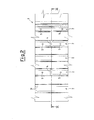
- a multi-stage axial compressor comprises a rotor disc 1 having a plurality of stages 2, each comprising, along its circumference, an array of circumferentially fixed blades 10.
- the blades 10 of each array are essentially identical, since their aerodynamic and structural behaviour must be identical.
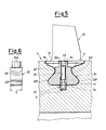
- the structure of a blade 10 essentially comprises three main portions: a quadrangular platform 11, preferably trapezoidal; a portion with an aerodynamic profile 12 designed to compress the air and extending from the upper face of the platform 11, and a root 13 which acts as the fixing in the rotor disc 1 and extends from the lower face of the platform 11.
- the root 13 is the portion by which the blade 10 is connected to the rotor disc 1, preventing the expulsion of the blade by centrifugal force.
- the root 13 is shaped in such a way as to form a partial fixing in a correspondingly shaped circumferential seat 3, formed along the circumference of the rotor disc 1.
- the fixing of the root 13 in the circumferential seat 3 is considered to be a partial fixing, since it allows the blade 10 to slide along the circumference of the rotor disc 1 but prevents its movement in the axial direction.
- the root 13 of the blade 10 and the circumferential seat 3 have profiles which match each other, and which can be made in various forms to meet different requirements of design and construction.
- the root 13 when seen from the front with respect to the direction of sliding in the circumferential seat 3, appears shaped in the form of a dovetail with rounded corners.
- the root 13 In its upper part, in the portion near the platform 11, the root 13 has a pair of recesses 13' which can engage with corresponding counterparts 3' formed along the walls of the circumferential seat 3.
- the root 13 also has at its base a pair of projections 13" retained in corresponding bends 3" formed in the walls of the circumferential seat 3 near the base.
- the recesses 13', the counterparts 3', the projections 13" and the bends 3" are made in pairs in the corresponding elements, but different forms of fixing which are equally effective can have only one shaped side.
- the root 13 has a thickness s measured in the direction of sliding of the blade 10 within the circumferential seat 3, and extends centrally with respect to the platform 11 which has in the same direction a side whose measurement L is essentially equal to twice the thickness s.
- the blades 10 are locked in the seat 3 by positioning and locking means, comprising at least one block 20, also shaped in the form of a dovetail with rounded corners, and having a thickness s essentially equal to the thickness of the root 13, subject to the various tolerances specified for assembly, and having a profile essentially reproducing that of the root 13, so that it can be inserted into, and slide within, the circumferential seat 3.
- positioning and locking means comprising at least one block 20, also shaped in the form of a dovetail with rounded corners, and having a thickness s essentially equal to the thickness of the root 13, subject to the various tolerances specified for assembly, and having a profile essentially reproducing that of the root 13, so that it can be inserted into, and slide within, the circumferential seat 3.
- the block 20 has in its upper part recesses 20' which reproduce the profiles of the counterparts 3' formed along the walls of the circumferential seat 3, and at its base a pair of projections 20" identical to the projections 13" of the roots 13 and capable of being retained in the bends 3" of the walls of the circumferential seat 3.
- the block 20 also has a thickness s, measured in the direction of sliding of the blade 10 and the block 20 within the circumferential seat 3, which is essentially equal to the thickness s of the roots 13, subject to the necessary assembly tolerances.
- At least two blocks 20 are provided, these being positioned a certain distance apart, according to the procedures which will be made clear in the rest of the description.
- Each block 20 has a central through hole 21, which passes vertically through it, for the insertion of a dowel 22.
- the dowel 22 of each block 20 comprises a body 23 and a head 24 designed for engagement in a corresponding blind hole 5 formed in the base of the circumferential seat 3 for fixing each block 20 to the rotor disc 1.
- the central hole 21 is threaded in the area which houses the body 23 of the dowel, which is also correspondingly threaded.
- At least one insertion slot 4 is provided, intersecting the said circumferential seat 3.
- a single insertion slot 4 is provided, in order to increase the reliability of the system, but the provision of two insertion slots 4 in diametrically opposite locations with respect to the rotor disc provides better balancing during rotation.
- the insertion slot 4 is, in practice, an aperture of essentially quadrangular shape, and its dimensions are slightly greater than the dimensions of the roots 13 and of the blocks 20, because sufficient assembly clearance is provided to enable the roots 13 and the blocks 20 to be inserted radially into the circumferential seat 3.
- Pairs of securing blades 10', located next to each block 20, are also provided for the assembly of the system according to the invention.
- These securing blades 10' are essentially identical to the blades 10, but each of them has an aperture 14, which is generally semicircular, or quadrangular if particular constructional requirements have to be met.
- This aperture 14 is formed on the edge of the platform 11, adjacent to the corresponding edge of the other securing blade making up the pair.
- These apertures are made in central positions, to allow access to the dowel 22.
- a small block or bush 20a extends from the upper face of the block 20a, this bush also being formed in a central position and having the central hole 21 passing through it.
- the bush 20a is designed to be inserted into the said semicircular or quadrangular apertures 14 formed in the platforms 11 of the securing blades 10'.
- the bush is also made quadrangular.
- the blades 10 are first inserted through the insertion slot 4 and are slid circumferentially along the circumferential seat 3, after which a securing blade 10' is inserted, followed by a block 20 and then another securing blade 10', in such a way that the two semicircular apertures 14 are joined to form an aperture which can receive the hollow cylindrical body 20a.
- the whole array is slid within the circumferential seat 3 until the two blocks 20, or more precisely their central holes 21, are brought in line with the blind holes 5, so that the dowels 22 can be screwed in until their heads 24 enter the blind holes 5.
- the blades 10 and the securing blades 10' are in contact with each other along the edges of their platforms 11 perpendicular to the direction of sliding of the blades, and a space is provided between the roots 13 of the two pairs of contiguous securing blades 10' for housing the blocks 20.
- this decision makes it possible to keep the blades which are close to the insertion slot 4 in their predetermined positions, and avoids a situation in which the insertion of a greater number of blades between the two blocks might, as a result of an unforeseen sum of tolerances, cause one of the blades to be too closely aligned with the insertion slot, thus risking the expulsion of this blade.
- the provision of a single insertion slot for the whole array of blades of each stage of the rotor disc further reduces the possibility of occurrence of such problems.
- the roots of the two blades are essentially aligned in the insertion slot 4, and it is therefore easy to imagine how a minimal displacement of the blade could bring its root into a position of excessive projection into the insertion slot, thus making the locking unstable or even causing the blade to be expelled from the circumferential seat during the rotation of the rotor disc.
- the arrangement according to the invention makes it possible to avoid an excessive closeness of the blocks which, by creating irregularities in the circular symmetry of the array of blades, perturb the rotation of the rotor disc.
Applications Claiming Priority (2)
| Application Number | Priority Date | Filing Date | Title |
|---|---|---|---|
| IT2001MI002783A ITMI20012783A1 (it) | 2001-12-21 | 2001-12-21 | Sistema di connessione e bloccaggio di pale rotoriche di un compressore assiale |
| ITMI20012783 | 2001-12-21 |
Publications (3)
| Publication Number | Publication Date |
|---|---|
| EP1321630A2 true EP1321630A2 (de) | 2003-06-25 |
| EP1321630A3 EP1321630A3 (de) | 2005-01-12 |
| EP1321630B1 EP1321630B1 (de) | 2007-06-06 |
Family
ID=11448748
Family Applications (1)
| Application Number | Title | Priority Date | Filing Date |
|---|---|---|---|
| EP02258736A Expired - Lifetime EP1321630B1 (de) | 2001-12-21 | 2002-12-18 | Verbindungs- und Verriegelungssystem für die Laufschaufeln eines Axialverdichters |
Country Status (9)
| Country | Link |
|---|---|
| US (1) | US6981847B2 (de) |
| EP (1) | EP1321630B1 (de) |
| JP (1) | JP2003206893A (de) |
| KR (1) | KR100779289B1 (de) |
| CA (1) | CA2414127C (de) |
| DE (1) | DE60220492T2 (de) |
| IT (1) | ITMI20012783A1 (de) |
| RU (1) | RU2296889C2 (de) |
| TW (1) | TWI280321B (de) |
Cited By (6)
| Publication number | Priority date | Publication date | Assignee | Title |
|---|---|---|---|---|
| EP1726780A2 (de) * | 2005-05-26 | 2006-11-29 | Rolls-Royce Deutschland Ltd & Co KG | Anordnung zum Feinauswuchten des Rotors eines Gasturbinentriebwerks |
| JP2007024043A (ja) * | 2005-07-14 | 2007-02-01 | United Technol Corp <Utc> | エンジン構成部品、エンジンに用いられるディスクおよびブレードの列、ガスタービンロータディスク、ロータブレードの挿入およびロック方法、ならびに構成部品固定システム |
| WO2008013610A1 (en) * | 2006-06-23 | 2008-01-31 | Siemens Energy, Inc | Turbine rotor blade groove entry slot lock structure |
| RU2484310C1 (ru) * | 2012-04-27 | 2013-06-10 | Федеральное государственное бюджетное учреждение науки Институт горного дела им. Н.А. Чинакала Сибирского отделения Российской академии наук | Рабочее колесо осевого вентилятора |
| US8523529B2 (en) | 2009-11-11 | 2013-09-03 | General Electric Company | Locking spacer assembly for a circumferential entry airfoil attachment system |
| CN104481594A (zh) * | 2014-10-28 | 2015-04-01 | 哈尔滨汽轮机厂有限责任公司 | 用于压气机周向环状燕尾型叶根的锁紧装置 |
Families Citing this family (36)
| Publication number | Priority date | Publication date | Assignee | Title |
|---|---|---|---|---|
| US7435055B2 (en) * | 2005-03-29 | 2008-10-14 | Siemens Power Generation, Inc. | Locking spacer assembly for a turbine engine |
| US7713029B1 (en) | 2007-03-28 | 2010-05-11 | Florida Turbine Technologies, Inc. | Turbine blade with spar and shell construction |
| US8894370B2 (en) * | 2008-04-04 | 2014-11-25 | General Electric Company | Turbine blade retention system and method |
| JP4886735B2 (ja) * | 2008-05-26 | 2012-02-29 | 株式会社東芝 | タービン動翼組立体および蒸気タービン |
| US8182230B2 (en) * | 2009-01-21 | 2012-05-22 | Pratt & Whitney Canada Corp. | Fan blade preloading arrangement and method |
| GB0908502D0 (en) * | 2009-05-19 | 2009-06-24 | Rolls Royce Plc | A balanced rotor for a turbine engine |
| US8485784B2 (en) * | 2009-07-14 | 2013-07-16 | General Electric Company | Turbine bucket lockwire rotation prevention |
| EP2295724B1 (de) * | 2009-08-28 | 2012-02-29 | Siemens Aktiengesellschaft | Leitschaufel für eine axial durchströmbare Turbomaschine und zugehörige Leitschaufelanordnung |
| US9890648B2 (en) * | 2012-01-05 | 2018-02-13 | General Electric Company | Turbine rotor rim seal axial retention assembly |
| US9051845B2 (en) * | 2012-01-05 | 2015-06-09 | General Electric Company | System for axial retention of rotating segments of a turbine |
| US8905716B2 (en) * | 2012-05-31 | 2014-12-09 | United Technologies Corporation | Ladder seal system for gas turbine engines |
| US9097131B2 (en) * | 2012-05-31 | 2015-08-04 | United Technologies Corporation | Airfoil and disk interface system for gas turbine engines |
| US20140286782A1 (en) * | 2012-08-07 | 2014-09-25 | Solar Turbines Incorporated | Turbine blade staking pin |
| EP2719866B1 (de) * | 2012-10-12 | 2018-12-05 | Safran Aero Boosters SA | Rotorscheibe einer Turbomaschine mit einem Verschlussstück für Laufradschaufeln |
| US9470092B2 (en) * | 2013-01-02 | 2016-10-18 | General Electric Company | System and method for attaching a rotating blade in a turbine |
| US9341071B2 (en) | 2013-10-16 | 2016-05-17 | General Electric Company | Locking spacer assembly |
| US9464531B2 (en) | 2013-10-16 | 2016-10-11 | General Electric Company | Locking spacer assembly |
| US9416670B2 (en) | 2013-10-16 | 2016-08-16 | General Electric Company | Locking spacer assembly |
| US9518471B2 (en) | 2013-10-16 | 2016-12-13 | General Electric Company | Locking spacer assembly |
| US9512732B2 (en) | 2013-10-16 | 2016-12-06 | General Electric Company | Locking spacer assembly inserted between rotor blades |
| RU2570087C1 (ru) * | 2014-08-22 | 2015-12-10 | Открытое акционерное общество "Уфимское моторостроительное производственное объединение" ОАО "УМПО" | Рабочее колесо ротора газотурбинного двигателя с демпфированием вибрационных колебаний |
| DE102014224844A1 (de) | 2014-12-04 | 2016-06-09 | Siemens Aktiengesellschaft | Rotor, Axialverdichter, Verfahren zur Montage |
| DE102015203290A1 (de) * | 2015-02-24 | 2016-09-29 | MTU Aero Engines AG | Sicherungselement und Strömungsmaschine |
| US9803647B2 (en) * | 2015-07-21 | 2017-10-31 | General Electric Company | Method and system for repairing turbomachine dovetail slots |
| KR102095033B1 (ko) * | 2017-05-30 | 2020-03-30 | 두산중공업 주식회사 | 베인 링 조립체 및 이를 포함하는 압축기, 가스터빈 |
| WO2019008724A1 (ja) * | 2017-07-06 | 2019-01-10 | 東芝エネルギーシステムズ株式会社 | タービン |
| KR102236266B1 (ko) * | 2017-11-17 | 2021-04-05 | 한화에어로스페이스 주식회사 | 회전체 |
| KR102193940B1 (ko) * | 2018-01-22 | 2020-12-22 | 두산중공업 주식회사 | 베인 링 조립체, 이의 조립방법 및 이를 포함하는 가스터빈 |
| RU195266U1 (ru) * | 2019-08-01 | 2020-01-21 | Игорь Николаевич Шевелёв | Рабочее колесо осевого вентилятора |
| US11486261B2 (en) * | 2020-03-31 | 2022-11-01 | General Electric Company | Turbine circumferential dovetail leakage reduction |
| KR102355521B1 (ko) | 2020-08-19 | 2022-01-24 | 두산중공업 주식회사 | 압축기 블레이드의 조립구조와 이를 포함하는 가스 터빈 및 압축기 블레이드의 조립방법 |
| CN114810220B (zh) * | 2021-01-29 | 2024-02-20 | 中国航发商用航空发动机有限责任公司 | 航空发动机 |
| CN114962289A (zh) * | 2021-02-19 | 2022-08-30 | 中国航发商用航空发动机有限责任公司 | 压气机以及航空发动机 |
| KR102587218B1 (ko) | 2021-07-29 | 2023-10-10 | 두산에너빌리티 주식회사 | 로터 및 이를 포함하는 터보머신 |
| CN114813041B (zh) * | 2022-04-01 | 2023-07-04 | 江苏经贸职业技术学院 | 一种基于网络安全用光纤检测设备 |
| CN116839810B (zh) * | 2023-08-30 | 2023-11-24 | 苏州海通机器人系统有限公司 | 一种发动机叶片质量矩自动测量系统及叶片装配方法 |
Citations (5)
| Publication number | Priority date | Publication date | Assignee | Title |
|---|---|---|---|---|
| GB122455A (en) * | 1918-01-21 | 1919-01-21 | Charles Algernon Parsons | Turbine Blade Attachments. |
| GB1015698A (en) * | 1963-10-24 | 1966-01-05 | Gen Electric | Improvements in rotor blade locking means for turbines or compressors |
| GB1509048A (en) * | 1974-06-14 | 1978-04-26 | Motoren Turbinen Union | Bladed rotor |
| GB2156908A (en) * | 1984-03-30 | 1985-10-16 | Rolls Royce | Bladed rotor assembly for gas turbine engine |
| EP1164251A1 (de) * | 2000-06-15 | 2001-12-19 | Snecma Moteurs | Schloss zur Sicherung von Laufschaufeln |
Family Cites Families (7)
| Publication number | Priority date | Publication date | Assignee | Title |
|---|---|---|---|---|
| US2315631A (en) * | 1942-02-14 | 1943-04-06 | Westinghouse Electric & Mfg Co | Turbine blade locking apparatus |
| US3088708A (en) * | 1961-12-29 | 1963-05-07 | Seymour J Feinberg | Compressor blade locking device |
| CH494341A (de) * | 1968-07-26 | 1970-07-31 | Sulzer Ag | Rotor für Turbomaschinen |
| US4314794A (en) * | 1979-10-25 | 1982-02-09 | Westinghouse Electric Corp. | Transpiration cooled blade for a gas turbine engine |
| GB2171150B (en) * | 1985-02-12 | 1989-07-26 | Rolls Royce Plc | Bladed rotor assembly for a turbomachine |
| US4859149A (en) * | 1989-03-10 | 1989-08-22 | General Motors Corporation | Blade locking system |
| USH1258H (en) * | 1992-09-16 | 1993-12-07 | The United States Of America As Represented By The Secretary Of The Air Force | Blade lock screw |
-
2001
- 2001-12-21 IT IT2001MI002783A patent/ITMI20012783A1/it unknown
-
2002
- 2002-12-12 CA CA2414127A patent/CA2414127C/en not_active Expired - Lifetime
- 2002-12-16 TW TW091136265A patent/TWI280321B/zh not_active IP Right Cessation
- 2002-12-16 US US10/319,462 patent/US6981847B2/en not_active Expired - Lifetime
- 2002-12-18 DE DE60220492T patent/DE60220492T2/de not_active Expired - Lifetime
- 2002-12-18 EP EP02258736A patent/EP1321630B1/de not_active Expired - Lifetime
- 2002-12-20 KR KR1020020081815A patent/KR100779289B1/ko active IP Right Grant
- 2002-12-20 JP JP2002369157A patent/JP2003206893A/ja active Pending
- 2002-12-20 RU RU2002134604/06A patent/RU2296889C2/ru active
Patent Citations (5)
| Publication number | Priority date | Publication date | Assignee | Title |
|---|---|---|---|---|
| GB122455A (en) * | 1918-01-21 | 1919-01-21 | Charles Algernon Parsons | Turbine Blade Attachments. |
| GB1015698A (en) * | 1963-10-24 | 1966-01-05 | Gen Electric | Improvements in rotor blade locking means for turbines or compressors |
| GB1509048A (en) * | 1974-06-14 | 1978-04-26 | Motoren Turbinen Union | Bladed rotor |
| GB2156908A (en) * | 1984-03-30 | 1985-10-16 | Rolls Royce | Bladed rotor assembly for gas turbine engine |
| EP1164251A1 (de) * | 2000-06-15 | 2001-12-19 | Snecma Moteurs | Schloss zur Sicherung von Laufschaufeln |
Cited By (12)
| Publication number | Priority date | Publication date | Assignee | Title |
|---|---|---|---|---|
| EP1726780A2 (de) * | 2005-05-26 | 2006-11-29 | Rolls-Royce Deutschland Ltd & Co KG | Anordnung zum Feinauswuchten des Rotors eines Gasturbinentriebwerks |
| DE102005025086A1 (de) * | 2005-05-26 | 2006-11-30 | Rolls-Royce Deutschland Ltd & Co Kg | Anordnung zum Feinauswuchten des Rotors eines Gasturbinentriebwerks |
| EP1726780A3 (de) * | 2005-05-26 | 2009-05-06 | Rolls-Royce Deutschland Ltd & Co KG | Anordnung zum Feinauswuchten des Rotors eines Gasturbinentriebwerks |
| DE102005025086B4 (de) * | 2005-05-26 | 2014-07-10 | Rolls-Royce Deutschland Ltd & Co Kg | Anordnung zum Feinauswuchten des Rotors eines Gasturbinentriebwerks |
| JP2007024043A (ja) * | 2005-07-14 | 2007-02-01 | United Technol Corp <Utc> | エンジン構成部品、エンジンに用いられるディスクおよびブレードの列、ガスタービンロータディスク、ロータブレードの挿入およびロック方法、ならびに構成部品固定システム |
| EP1744013A3 (de) * | 2005-07-14 | 2008-09-10 | United Technologies Corporation | Verfahren zur Montage und tangentieller Verriegelung von Rotorschaufeln sovie Rotorschaufel |
| US8206116B2 (en) | 2005-07-14 | 2012-06-26 | United Technologies Corporation | Method for loading and locking tangential rotor blades and blade design |
| WO2008013610A1 (en) * | 2006-06-23 | 2008-01-31 | Siemens Energy, Inc | Turbine rotor blade groove entry slot lock structure |
| US7901187B2 (en) | 2006-06-23 | 2011-03-08 | Siemens Energy, Inc. | Turbine rotor blade groove entry slot lock structure |
| US8523529B2 (en) | 2009-11-11 | 2013-09-03 | General Electric Company | Locking spacer assembly for a circumferential entry airfoil attachment system |
| RU2484310C1 (ru) * | 2012-04-27 | 2013-06-10 | Федеральное государственное бюджетное учреждение науки Институт горного дела им. Н.А. Чинакала Сибирского отделения Российской академии наук | Рабочее колесо осевого вентилятора |
| CN104481594A (zh) * | 2014-10-28 | 2015-04-01 | 哈尔滨汽轮机厂有限责任公司 | 用于压气机周向环状燕尾型叶根的锁紧装置 |
Also Published As
| Publication number | Publication date |
|---|---|
| EP1321630A3 (de) | 2005-01-12 |
| DE60220492D1 (de) | 2007-07-19 |
| EP1321630B1 (de) | 2007-06-06 |
| TWI280321B (en) | 2007-05-01 |
| TW200411121A (en) | 2004-07-01 |
| US6981847B2 (en) | 2006-01-03 |
| KR100779289B1 (ko) | 2007-11-23 |
| CA2414127C (en) | 2010-07-20 |
| RU2296889C2 (ru) | 2007-04-10 |
| JP2003206893A (ja) | 2003-07-25 |
| KR20030053437A (ko) | 2003-06-28 |
| CA2414127A1 (en) | 2003-06-21 |
| DE60220492T2 (de) | 2008-01-31 |
| US20040037703A1 (en) | 2004-02-26 |
| ITMI20012783A1 (it) | 2003-06-21 |
Similar Documents
| Publication | Publication Date | Title |
|---|---|---|
| CA2414127C (en) | System for connecting and locking rotor blades of an axial compressor | |
| US3501249A (en) | Side plates for turbine blades | |
| EP0799972B1 (de) | Befestigung einer Turbomaschinenschaufel | |
| EP1312757A2 (de) | Verfahren und Vorrichtung zur Kühlung der Leitschaufeln einer Gasturbine | |
| JP6563631B2 (ja) | ロック用スペーサアセンブリ | |
| US8770938B2 (en) | Rotor for an axial-throughflow turbomachine and moving blade for such a rotor | |
| JPH0320561B2 (de) | ||
| CA2566524A1 (en) | Bladed disk fixing undercut | |
| EP3380704A1 (de) | Flexibler dämpfer für turbinenschaufeln | |
| EP3388634B1 (de) | Gasturbinenschaufel mit haltermontagestruktur und gasturbine damit | |
| CN106414906B (zh) | 用于组装燃气涡轮发动机的定子级的方法 | |
| KR101997979B1 (ko) | 블레이드 에어포일, 터빈 및 이를 포함하는 가스터빈 | |
| JP7196120B2 (ja) | タービンホイール | |
| JP7275445B2 (ja) | 回転機械、これを含むガスタービン、回転機械の組立方法 | |
| EP1792055B1 (de) | Schutzeinrichtung für ein turbinegehäuse | |
| US11560805B2 (en) | Rotor and turbo machine including same | |
| KR102400013B1 (ko) | 터빈 블레이드의 씰 조립구조와 이를 포함하는 가스 터빈 및 터빈 블레이드의 씰 조립방법 | |
| KR102319765B1 (ko) | 가스 터빈 | |
| KR20220012472A (ko) | 로터 및 이를 포함하는 터보머신 | |
| RU2296864C1 (ru) | Рабочее колесо осевой турбомашины | |
| KR102284507B1 (ko) | 로터 및 이를 포함하는 터보머신 | |
| KR20210031972A (ko) | 유동 인듀서를 갖는 커버 플레이트 및 터빈 블레이드들을 냉각하기 위한 방법 | |
| KR102480278B1 (ko) | 로터 및 이를 포함하는 터보머신 | |
| KR101984397B1 (ko) | 로터, 터빈 및 이를 포함하는 가스터빈 | |
| KR102141626B1 (ko) | 터빈장치 |
Legal Events
| Date | Code | Title | Description |
|---|---|---|---|
| PUAI | Public reference made under article 153(3) epc to a published international application that has entered the european phase |
Free format text: ORIGINAL CODE: 0009012 |
|
| AK | Designated contracting states |
Designated state(s): AT BE BG CH CY CZ DE DK EE ES FI FR GB GR IE IT LI LU MC NL PT SE SI SK TR |
|
| AX | Request for extension of the european patent |
Extension state: AL LT LV MK RO |
|
| PUAL | Search report despatched |
Free format text: ORIGINAL CODE: 0009013 |
|
| AK | Designated contracting states |
Kind code of ref document: A3 Designated state(s): AT BE BG CH CY CZ DE DK EE ES FI FR GB GR IE IT LI LU MC NL PT SE SI SK TR |
|
| AX | Request for extension of the european patent |
Extension state: AL LT LV MK RO |
|
| 17P | Request for examination filed |
Effective date: 20050712 |
|
| AKX | Designation fees paid |
Designated state(s): CH DE FR GB LI NL |
|
| GRAP | Despatch of communication of intention to grant a patent |
Free format text: ORIGINAL CODE: EPIDOSNIGR1 |
|
| GRAS | Grant fee paid |
Free format text: ORIGINAL CODE: EPIDOSNIGR3 |
|
| GRAA | (expected) grant |
Free format text: ORIGINAL CODE: 0009210 |
|
| AK | Designated contracting states |
Kind code of ref document: B1 Designated state(s): CH DE FR GB LI NL |
|
| REG | Reference to a national code |
Ref country code: GB Ref legal event code: FG4D |
|
| REG | Reference to a national code |
Ref country code: CH Ref legal event code: EP |
|
| REF | Corresponds to: |
Ref document number: 60220492 Country of ref document: DE Date of ref document: 20070719 Kind code of ref document: P |
|
| REG | Reference to a national code |
Ref country code: CH Ref legal event code: NV Representative=s name: SERVOPATENT GMBH |
|
| ET | Fr: translation filed | ||
| REG | Reference to a national code |
Ref country code: CH Ref legal event code: PFA Owner name: NUOVO PIGNONE HOLDING S.P.A. Free format text: NUOVO PIGNONE HOLDING S.P.A.#2, VIA FELICE MATTEUCCI#50127 FIRENZE (IT) -TRANSFER TO- NUOVO PIGNONE HOLDING S.P.A.#2, VIA FELICE MATTEUCCI#50127 FIRENZE (IT) |
|
| PLBE | No opposition filed within time limit |
Free format text: ORIGINAL CODE: 0009261 |
|
| STAA | Information on the status of an ep patent application or granted ep patent |
Free format text: STATUS: NO OPPOSITION FILED WITHIN TIME LIMIT |
|
| 26N | No opposition filed |
Effective date: 20080307 |
|
| REG | Reference to a national code |
Ref country code: FR Ref legal event code: PLFP Year of fee payment: 14 |
|
| REG | Reference to a national code |
Ref country code: FR Ref legal event code: PLFP Year of fee payment: 15 |
|
| REG | Reference to a national code |
Ref country code: FR Ref legal event code: PLFP Year of fee payment: 16 |
|
| REG | Reference to a national code |
Ref country code: CH Ref legal event code: PCAR Free format text: NEW ADDRESS: WANNERSTRASSE 9/1, 8045 ZUERICH (CH) |
|
| PGFP | Annual fee paid to national office [announced via postgrant information from national office to epo] |
Ref country code: NL Payment date: 20201125 Year of fee payment: 19 |
|
| PGFP | Annual fee paid to national office [announced via postgrant information from national office to epo] |
Ref country code: FR Payment date: 20201120 Year of fee payment: 19 Ref country code: GB Payment date: 20201123 Year of fee payment: 19 Ref country code: CH Payment date: 20201119 Year of fee payment: 19 Ref country code: DE Payment date: 20201119 Year of fee payment: 19 |
|
| REG | Reference to a national code |
Ref country code: DE Ref legal event code: R119 Ref document number: 60220492 Country of ref document: DE |
|
| REG | Reference to a national code |
Ref country code: CH Ref legal event code: PL |
|
| REG | Reference to a national code |
Ref country code: NL Ref legal event code: MM Effective date: 20220101 |
|
| GBPC | Gb: european patent ceased through non-payment of renewal fee |
Effective date: 20211218 |
|
| PG25 | Lapsed in a contracting state [announced via postgrant information from national office to epo] |
Ref country code: NL Free format text: LAPSE BECAUSE OF NON-PAYMENT OF DUE FEES Effective date: 20220101 |
|
| PG25 | Lapsed in a contracting state [announced via postgrant information from national office to epo] |
Ref country code: GB Free format text: LAPSE BECAUSE OF NON-PAYMENT OF DUE FEES Effective date: 20211218 Ref country code: DE Free format text: LAPSE BECAUSE OF NON-PAYMENT OF DUE FEES Effective date: 20220701 |
|
| PG25 | Lapsed in a contracting state [announced via postgrant information from national office to epo] |
Ref country code: FR Free format text: LAPSE BECAUSE OF NON-PAYMENT OF DUE FEES Effective date: 20211231 |
|
| PG25 | Lapsed in a contracting state [announced via postgrant information from national office to epo] |
Ref country code: LI Free format text: LAPSE BECAUSE OF NON-PAYMENT OF DUE FEES Effective date: 20211231 Ref country code: CH Free format text: LAPSE BECAUSE OF NON-PAYMENT OF DUE FEES Effective date: 20211231 |