EP1321355A2 - Method for connecting vehicle body parts with a weld line - Google Patents
Method for connecting vehicle body parts with a weld line Download PDFInfo
- Publication number
- EP1321355A2 EP1321355A2 EP02026615A EP02026615A EP1321355A2 EP 1321355 A2 EP1321355 A2 EP 1321355A2 EP 02026615 A EP02026615 A EP 02026615A EP 02026615 A EP02026615 A EP 02026615A EP 1321355 A2 EP1321355 A2 EP 1321355A2
- Authority
- EP
- European Patent Office
- Prior art keywords
- seam
- roof part
- component
- roof
- side wall
- Prior art date
- Legal status (The legal status is an assumption and is not a legal conclusion. Google has not performed a legal analysis and makes no representation as to the accuracy of the status listed.)
- Granted
Links
Images


Classifications
-
- B—PERFORMING OPERATIONS; TRANSPORTING
- B62—LAND VEHICLES FOR TRAVELLING OTHERWISE THAN ON RAILS
- B62D—MOTOR VEHICLES; TRAILERS
- B62D65/00—Designing, manufacturing, e.g. assembling, facilitating disassembly, or structurally modifying motor vehicles or trailers, not otherwise provided for
- B62D65/02—Joining sub-units or components to, or positioning sub-units or components with respect to, body shell or other sub-units or components
Definitions
- the invention relates to a method for connecting a first body component and a second body component with a connecting seam a seam according to the preamble of claim 1.
- connection results can be partially unsatisfactory.
- Methods and devices are also from DE 198 06 963 A1 and DE 33 46 523 C2 for feeding, clamping and processing, in particular for geometry welding of components for the automated production of body shells in one or more processing stations using robots known. It is known from DE 33 46 523 C2 to achieve Seaming joints with a small joint width include a roof section with side bends bent downwards Roof part connecting flanges between opposite roof side rails clamp under pretension. However, this is tolerance-dependent Bends connected, which in turn lead to unacceptable Deviations in dimensions or large internal stresses in the component can.
- the object of the invention is a generic method for connection of body parts, in particular roof side rails with one To further develop the roof part so that a stable connection and an exact predetermined Position of a connecting seam can be reached.
- the body components are in the area of the seam
- Tensioning points held by actuating and tensioning units which are dependent of metrologically recorded component contours there for a mutual Component contour alignment and component contour adjustment for extensive elimination can be adjusted according to component tolerances in the seam joint area.
- connection By such a controlled alignment and adjustment of those forming the seam Component contours using actuating and clamping units immediately before and while maintaining the positioning positions of the positioning and clamping units during The implementation of the connection can tolerances in the seam joint area largely eliminated so that it is optimally stable and in the correct position Connections can be made.
- connection preparation is particularly advantageous according to claim 2 through an adapted seam joint for laser soldering with joint widths of a maximum of 0.2 mm should not be exceeded.
- the connecting seam can also be used as a laser weld with filler material in a fillet or V seam getting produced.
- contour setpoints can be stored setpoint coordinate data be and / or possibly from the determined actual values of the respective neighboring component contour for a mutual optimal adjustment be derived. Then using a control algorithm the determined corrective measures in manipulated values for the actuating and clamping units implemented and there for the controlled elimination of component tolerances in the Area of the seam joint, in particular for creating an optimal parallelism used.
- the components during the metrological Detection and alignment for the time being in the area of the seam joint while observing of a measuring and straightening gap.
- Well-suited measuring and Straightening gap widths are approximately 5 mm to 10 mm. Depending on the circumstances larger or smaller gap widths may also be appropriate.
- clamping and actuating devices can have several, each different directions can be arranged and combined.
- a relative simple and suitable for common alignments and adjustments sufficient arrangement is proposed with claim 5.
- the Setting directions of the positioning and clamping units for a first component contour for example aligned axially parallel and the adjustment directions of the actuating and clamping devices for the other second component contour, however, are again axially parallel offset by 90 ° to the first setting directions.
- the method according to the invention is particularly preferred when joining the Roof area of a body shell used, the first body component is a roof side member on a side wall part and the second body component is each a roof part connecting flange of a roof part.
- the roof section is a surface element on which the roof section connecting flanges are on both sides are bent downwards, the roof part with the roof part connecting flanges between the roof side rails, forming two-sided Seam joints can be used with adjacent and aligned component contours is.
- there are between the roof side rails and the roof part connection flanges long seams and seams because of the relative large dimensional tolerances of the components to be connected are particularly critical are.
- the side wall parts are according to claim 7 in a manner known per se if necessary with further already assembled body components, especially with an already built substructure of a laser soldering station, the Side wall parts in the correct position on a side wall support in a laser soldering station construction locked in the manner of a stable steel construction portal.
- the position of the roof side rails is already relatively precisely defined, however nor the alignments and adaptations for elimination according to the invention dimensional tolerances.
- the roof part is then held on a roof part carrier from above in the area above and between the roof side rails so far, that each have a measuring and straightening gap in the area of the side seam joints remains.
- the geometric measurement is carried out using cameras, depending on the conditions on the side wall support and / or on the laser soldering station structure and / or can be arranged on the roof part carrier.
- side wall adjustment and clamping units with steep directions mounted in the vehicle transverse direction (Y direction) which on the roof side rails attack to apply pressure or pull. This regulates an alignment preferably with respect to stored target coordinate positions in the Y direction.
- roof part positioning and clamping units arranged on the roof part in the area of the roof part connection flanges attack and there regulated by pressure or tension set travel ranges, align and adjust in the Z direction.
- Suitable clamping points which are designed to be movable in a controlled manner according to claim 8 in the area of the roof pillars. This results in each case three adjacent positioning and tensioning units for the side wall and the roof part in the upper area of the A, B and C pillar or in the one above Roof area are arranged. Depending on the specific circumstances and depending on the need, more or less such positioning and Clamping units are used.
- a ball screw drive is assigned to the slide guide, which is suitable for very precise adjustment and positioning.
- At least one tensioning device should then be on the end of the adjustable slide be attached, which for holding and tensioning purposes on an associated Body component attacks in the area of the relevant component contour.
- such a clamping device arranged on the carriage have pliers elements and / or suction plates in a manner known per se, wherein the clamping device also on the respective component contour can contain adapted contact surfaces.
- Such pliers elements are special for mounting and connection with the side parts in the area of the roof pillars can be used.
- the specified Suction cups are used for connecting the roof section adjustment and clamping units with the flat roof part.
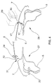
- a laser soldering station 1 is shown schematically.
- the base of the laser soldering station 1 is a laser soldering station assembly 2 designed as a steel construction portal.
- On the side wall support 3 is in the correct position and stationary a side wall part 5 attachable to the roof part support 4 is in the correct position and a roof part 6 can be attached in a stationary manner.
- the side wall part 5 has a roof side rail 7 and in the area of an A pillar 8, a B pillar 9 and a C pillar 10 each have a clamping point 11 in the area of the roof side member 7.
- Am Roof part 6 is laterally a roof part connecting flange in the vehicle longitudinal direction 12 trained.
- the B pillar 9 and the C pillar 10 12 clamping points 13 are formed in the roof part connecting flange.
- Cameras 14 are located both on the roof part support 4 and on the side wall support 3 arranged to accommodate the respective component contour.
- On the roof part carrier 4 are three roof part positioning Clamping units 16 arranged at the clamping points 13 of the roof part connecting flange Attack 12.
- the side wall bracket 3 and the roof section bracket 4 are with the components arranged thereon, the side wall part 5 and the roof part 6, can be moved relative to one another such that a roof joint 17 can be formed is.
- the second side wall part of the motor vehicle, the holding elements of the Roof part carrier 4, with which the roof part 6 is held on the roof part carrier 4, and a robot with a laser soldering head for making a joint are between the side wall part 5 and the roof part 6 for reasons of clarity not shown.
- the side wall adjusting and clamping unit 15 is shown schematically.
- a slide 19 is in the transverse direction of the vehicle by means of a ball screw drive 18 20 movable. With the ball screw drive 18 is a position accuracy achievable of ⁇ 0.02 mm.
- On the carriage 19 is a clamping device 21 arranged which engages the clamping point 11 of the side wall part 5.
- 2 shows the B-pillar 9 of the side wall part 5 in the area of the roof side rail 7 shown in dashed lines.
- FIG. 3 the roof part adjusting and tensioning unit 16 is shown schematically.
- a slide 23 is in the vehicle vertical direction by means of a ball screw drive 22 24 movable. With the ball screw drive 22 is a position accuracy of plus / minus 0.02 mm achievable.
- the contour piece 25 corresponds to the area of the roof part 6 in the form customized.
- a section of the roof section is shown in dashed lines.
- FIG. 4 is a schematic section in the transverse direction of the vehicle in the region of the Roof part 6 shown.
- the roof part 6 is still shown lifted off from the side wall part 3.
- This represents the measurement and Alignment position 27 represents a potential regulated with the double arrows Align and adjust the seam, which is formed as a roof joint 17 is drawn in the vehicle transverse direction 20 and in the vehicle vertical direction 24.
- the roof part 6 and the side wall part 5 shown in your laser soldering position 28.
- With a laser soldering head shown in dashed lines 29 a laser solder seam 30 is made along the roof joint 17 for connection of the roof part 6 with the side wall part 5.
- Using cameras 14 the relevant component contours of the roof part 6 and the side wall part 5 recorded, with recorded measurement data as actual values of one not shown here Measuring and control device are supplied. There these actual values compared with contour setpoints and corrective measures determined.
Abstract
Description
Die Erfindung betrifft ein Verfahren zur Verbindung eines ersten Karosseriebauteils und eines zweiten Karosseriebauteils mit einer Verbindungsnaht an einer Nahtfuge nach dem Oberbegriff des Anspruchs 1.The invention relates to a method for connecting a first body component and a second body component with a connecting seam a seam according to the preamble of claim 1.
Mit einem gattungsgemäßen Verfahren aus der DE 195 23 005 A1 ist es bekannt im Übergang vom Dach in die Seitenteile einer Fahrzeugkarosserie jeweils eine Regenrinne auszubilden, wobei im Regenrinnenbereich einander überlappende Bleche vom Dachteil und den Seitenwandteilen von oben her durch Laserschweißen verbunden werden. Konkret wird durch eine von einem Dachteil abgestellte Seitenwange und durch einen an der zugehörigen Seitenwand angeformten Flansch eine Kehle gebildet, die mittels eines Laserstrahls verschweißt wird. Gegebenenfalls können dazu in einem Laserlötverfahren Zusatzdrähte verwendet werden. Damit soll eine stabile Verbindung mit einer Verbindungsnaht, die keinerlei Nacharbeit erfordert, erreicht werden.It is known using a generic method from DE 195 23 005 A1 in the transition from the roof to the side parts of a vehicle body form a gutter, with each other in the gutter area overlapping sheets from the roof part and the side wall parts from above be connected by laser welding. Specifically, one by one The side panel is parked on the roof section and through one on the associated side wall molded flange formed a throat using a laser beam is welded. If necessary, additional wires can be used for this in a laser soldering process be used. This is intended to establish a stable connection with a Connection seam that requires no reworking can be achieved.
Dies ist jedoch nur dann zu erreichen, wenn vor der Verbindung die angrenzenden Bauteile genau lagerichtig mit einer Nahtfuge mit geringem Fugenmaß aneinandergeführt werden. Für eine Verbindung durch Laserlöten ist für eine optimale und prozesssichere Verbindungsnaht ein Fugenmaß von 0 mm bis maximal +0,2 mm zu gewährleisten, wobei eine Nullfuge anzustreben ist. Zudem sind für eine gute Anmutung eines solchen Übergangs gleichmäßige und genaue Kanten- und Sickenverläufe zu gewährleisten, so dass vor der Verbindung eine entsprechend genaue Relativlage der Bauteile sicherzustellen ist. Diese Bedingungen sind aufgrund der Fertigungstoleranzen der hier verwendeten Blechbauteile nicht immer einzuhalten, so dass die Verbindungsergebnisse teilweise unbefriedigend sein können.However, this can only be achieved if the adjacent ones before the connection Components exactly in the correct position with a seam joint with a small joint dimension be brought together. For a connection by laser soldering is for one optimal and reliable connection seam from 0 mm to to ensure a maximum of +0.2 mm, whereby a zero joint should be aimed for. moreover are even and for a good appearance of such a transition to ensure exact edges and beads, so that before the connection a correspondingly accurate relative position of the components must be ensured. These conditions are due to the manufacturing tolerances used here Sheet metal components not always adhered to, so the connection results can be partially unsatisfactory.
In der DE 37 20 344 A1 ist ein Herstellverfahren für Kraftfahrzeug-Rohkarossen beschrieben, bei dem zunächst ein Unterbau zusammengesetzt und dann Seitenteile an den Unterbau angesetzt und festgelegt werden. Dabei ist auf die Problematik hingewiesen, dass die Querabstände zwischen den Seitenteilen insbesondere im Bereich von oberen Pfostenenden aufgrund von Form- und Fügetoleranzen variieren können. Maßabweichungen sollen hier dadurch verhindert werden, dass ein separater Dachrahmen maßgenau unter Verwendung einer Lehre hergestellt wird, der dann in den Unterbau eingesetzt und darin festgelegt wird. Maßabweichungen an Verbindungsstellen, die durch Toleranzen des später auf den Dachrahmen aufgesetzten flächigen Dachteils bedingt sind, können damit nicht behoben werden.DE 37 20 344 A1 describes a manufacturing process for motor vehicle body shells described, in which a substructure was first assembled and then Side parts are attached to the substructure and fixed. It is on the Problem pointed out that the transverse distances between the side parts especially in the area of upper post ends due to shape and Joining tolerances can vary. This is to prevent dimensional deviations be using a separate roof frame that is true to size a teaching is produced, which is then inserted into the substructure and in it is set. Dimensional deviations at connection points due to tolerances conditional on the flat roof part later placed on the roof frame cannot be corrected.
Aus DE 198 06 963 A1 und DE 33 46 523 C2 sind zudem Verfahren und Vorrichtungen zum Zuführen, Spannen und Bearbeiten insbesondere zum Geometrieschweißen von Bauteilen zur automatisierten Herstellung von Rohkarossen in einer oder mehreren Bearbeitungsstationen unter Verwendung von Robotern bekannt. Dabei ist es aus DE 33 46 523 C2 bekannt zum Erreichen von Nahtfugen geringer Fugenweite ein Dachteil mit nach unten abgebogenen seitlichen Dachteil-Anschlussflanschen zwischen gegenüberliegende Dachseitenholme unter Vorspannung einzuklemmen. Damit sind jedoch toleranzabhängige Verbiegungen verbunden, die ihrerseits wiederum zu nicht hinnehmbaren Maßabweichungen führen bzw. große Eigenspannungen im Bauteil bewirken können.Methods and devices are also from DE 198 06 963 A1 and DE 33 46 523 C2 for feeding, clamping and processing, in particular for geometry welding of components for the automated production of body shells in one or more processing stations using robots known. It is known from DE 33 46 523 C2 to achieve Seaming joints with a small joint width include a roof section with side bends bent downwards Roof part connecting flanges between opposite roof side rails clamp under pretension. However, this is tolerance-dependent Bends connected, which in turn lead to unacceptable Deviations in dimensions or large internal stresses in the component can.
Aufgabe der Erfindung ist es ein gattungsgemäßes Verfahren zur Verbindung von Karosseriebauteilen, insbesondere von Dachseitenholmen mit einem Dachteil so weiterzubilden, dass eine stabile Verbindung und eine genaue vorgegebene Lage einer Verbindungsnaht erreicht werden.The object of the invention is a generic method for connection of body parts, in particular roof side rails with one To further develop the roof part so that a stable connection and an exact predetermined Position of a connecting seam can be reached.
Diese Aufgabe wird mit den Merkmalen des Anspruchs 1 gelöst.This object is achieved with the features of claim 1.
Gemäß Anspruch 1 sind die Karosseriebauteile im Bereich der Nahtfuge an Spannstellen mittels Stell- und Spanneinheiten gehalten, die in Abhängigkeit von messtechnisch erfassten, dortigen Bauteilkonturen für eine gegenseitige Bauteilkonturausrichtung und Bauteilkonturanpassung zur weitgehenden Eliminierung von Bauteiltoleranzen im Nahtfugenbereich geregelt verstellbar sind. Nach einer solchen Bauteilkonturausrichtung und Bauteilkonturanpassung werden die Bauteile mit einer Nahtfuge mit geringem Fugenmaß insbesondere als Nullfuge zugestellt. Anschließend wird die Verbindungsnaht angebracht.According to claim 1, the body components are in the area of the seam Tensioning points held by actuating and tensioning units, which are dependent of metrologically recorded component contours there for a mutual Component contour alignment and component contour adjustment for extensive elimination can be adjusted according to component tolerances in the seam joint area. After such a component contour alignment and component contour adjustment the components with a seam with a small joint size in particular delivered as zero joint. The connecting seam is then attached.
Durch ein solches geregeltes Ausrichten und Anpassen der die Nahtfuge bildenden Bauteilkonturen mittels Stell- und Spanneinheiten unmittelbar vor und unter Beibehaltung der Stellpositionen der Stell- und Spanneinheiten während der Durchführung der Verbindung können Toleranzen im Nahtfugenbereich weitestgehend eliminiert werden, so dass optimal stabile und lagerichtig genaue Verbindungen herstellbar sind.By such a controlled alignment and adjustment of those forming the seam Component contours using actuating and clamping units immediately before and while maintaining the positioning positions of the positioning and clamping units during The implementation of the connection can tolerances in the seam joint area largely eliminated so that it is optimally stable and in the correct position Connections can be made.
Besonders vorteilhaft ist nach Anspruch 2 eine solche Verbindungsvorbereitung durch eine angepasste Nahtfuge für ein Laserlöten wobei Fugenweiten von maximal 0,2 mm nicht überschritten werden sollen. Die Verbindungsnaht kann auch als Laserschweißnaht mit Zusatzwerkstoff in einer Kehl- oder V-Naht hergestellt werden.Such a connection preparation is particularly advantageous according to claim 2 through an adapted seam joint for laser soldering with joint widths of a maximum of 0.2 mm should not be exceeded. The connecting seam can also be used as a laser weld with filler material in a fillet or V seam getting produced.
Gemäß Anspruch 3 kann durch an sich bekannte optische oder Laser- oder taktile Messsensoren in der Art von Kameras oder Lasersensoren bzw. taktiler Sensorik die Geometrie der relevanten Bauteilkonturen erfasst werden, wobei erfasste Messdaten als Istwerte einer Mess- und Regeleinrichtung zugeführt werden. Dort werden diese Istwerte mit Kontursollwerten verglichen und Korrekturmaße ermittelt. Solche Kontursollwerte können gespeicherte Soll-Koordinatendaten sein und/oder ggf. aus den ermittelten Istwerten der jeweils benachbarten Bauteilkontur für eine gegenseitige optimale Anpassung abgeleitet werden. Unter Verwendung eines Regelalgorithmus werden dann die ermittelten Korrekturmaße in Stellwerte für die Stell- und Spanneinheiten umgesetzt und dort für die geregelte Eliminierung von Bauteiltoleranzen im Bereich der Nahtfuge insbesondere zur Herstellung einer optimalen Parallelität verwendet.According to claim 3 can by known optical or laser or tactile measuring sensors in the manner of cameras or laser sensors or tactile Sensors, the geometry of the relevant component contours are recorded, whereby recorded measurement data are fed as actual values to a measuring and control device become. There, these actual values are compared with contour setpoints and Corrective measures determined. Such contour setpoints can be stored setpoint coordinate data be and / or possibly from the determined actual values of the respective neighboring component contour for a mutual optimal adjustment be derived. Then using a control algorithm the determined corrective measures in manipulated values for the actuating and clamping units implemented and there for the controlled elimination of component tolerances in the Area of the seam joint, in particular for creating an optimal parallelism used.
Damit die messtechnische Erfassung und Ausrichtung störungsfrei möglich ist wird mit Anspruch 4 vorgeschlagen die Bauteile während der messtechnischen Erfassung und Ausrichtung vorerst im Bereich der Nahtfuge unter Einhaltung eines Mess- und Richtspalts gegeneinander zu führen. Gutgeeignete Messund Richtspaltweiten liegen etwa bei 5 mm bis 10 mm. Je nach den Gegebenheiten können auch größere oder kleinere Spaltweiten zweckmäßig sein. Erst nach Abschluss der Ausrichtungen und Anpassungen werden die Bauteile unter Beibehaltung der jeweiligen Stellpositionen der Spann- und Stelleinheiten an der Nahtfuge zur Anlage gebracht und die Verbindungsnaht hergestellt.So that the metrological recording and alignment is possible without interference is proposed with claim 4, the components during the metrological Detection and alignment for the time being in the area of the seam joint while observing of a measuring and straightening gap. Well-suited measuring and Straightening gap widths are approximately 5 mm to 10 mm. Depending on the circumstances larger or smaller gap widths may also be appropriate. First After completing the alignments and adjustments, the components are under Maintaining the respective positions of the clamping and actuating units brought into contact with the seam and made the connecting seam.
Grundsätzlich können Spann- und Stelleinrichtungen mit mehreren, jeweils
unterschiedlichen Stellrichtungen angeordnet und kombiniert werden. Eine relativ
einfache und für übliche Ausrichtungen und Anpassungen geeignete und
ausreichende Anordnung wird mit Anspruch 5 vorgeschlagen. Dabei sind die
Stellrichtungen der Stell- und Spanneinheiten für eine erste Bauteilkontur etwa
achsparallel ausgerichtet und die Stellrichtungen der Stell- und Spanneinrichtungen
für die andere zweite Bauteilkontur liegen wiederum achsparallel jedoch
zu den ersten Stellrichtungen um 90° versetzt.Basically, clamping and actuating devices can have several, each
different directions can be arranged and combined. A relative
simple and suitable for common alignments and adjustments
sufficient arrangement is proposed with
Besonders bevorzugt wird das erfindungsgemäße Verfahren beim Fügen des Dachbereichs einer Rohkarosse verwendet, wobei das erste Karosseriebauteil jeweils ein Dachseitenholm an einem Seitenwandteil ist und das zweite Karosseriebauteil jeweils ein Dachteil-Anschlussflansch eines Dachteils ist. Das Dachteil ist hier ein Flächenelement an dem beidseitig die Dachteil-Anschlussflansche nach unten abgebogen sind, wobei das Dachteil mit den Dachteil-Anschlussflanschen zwischen die Dachseitenholme unter Bildung beidseitiger Nahtfugen mit angrenzenden und auszurichtenden Bauteilkonturen einsetzbar ist. Hier ergeben sich zwischen den Dachseitenholmen und den Dachteilanschlussflanschen lange Nahtfugen und Verbindungsnähte die wegen der relativ großen Maßtoleranzen der zu verbindenden Bauteile besonders kritisch sind.The method according to the invention is particularly preferred when joining the Roof area of a body shell used, the first body component is a roof side member on a side wall part and the second body component is each a roof part connecting flange of a roof part. The The roof section is a surface element on which the roof section connecting flanges are on both sides are bent downwards, the roof part with the roof part connecting flanges between the roof side rails, forming two-sided Seam joints can be used with adjacent and aligned component contours is. Here there are between the roof side rails and the roof part connection flanges long seams and seams because of the relative large dimensional tolerances of the components to be connected are particularly critical are.
Dabei werden nach Anspruch 7 in an sich bekannter Weise die Seitenwandteile
ggf. mit weiteren bereits gefügten Karosseriebauteilen, insbesondere mit
einem bereits hergestellten Unterbau einer Laserlötstation zugeführt, wobei die
Seitenwandteile lagerichtig an einem Seitenwandträger in einem Laserlötstation-Aufbau
in der Art eines stabilen Stahlbauportals verriegelt werden. Damit
ist bereits die Lage der Dachseitenholme relativ genau festgelegt, wobei jedoch
noch die erfindungsgemäßen Ausrichtungen und Anpassungen zur Eliminierung
von Maßtoleranzen durchgeführt werden sollen.The side wall parts are according to
Dazu wird dann das Dachteil, gehalten an einem Dachteilträger von oben her in den Bereich oberhalb und zwischen den Dachseitenholmen so weit zugestellt, dass jeweils ein Mess- und Richtspalt im Bereich der seitlichen Nahtfugen verbleibt. Die geometrische Vermessung wird mittels Kameras durchgeführt, die je nach den Gegebenheiten am Seitenwandträger und/oder am Laserlötstation-Aufbau und/oder am Dachteilträger angeordnet sein können.The roof part is then held on a roof part carrier from above in the area above and between the roof side rails so far, that each have a measuring and straightening gap in the area of the side seam joints remains. The geometric measurement is carried out using cameras, depending on the conditions on the side wall support and / or on the laser soldering station structure and / or can be arranged on the roof part carrier.
Für eine Ausrichtung der relevanten Kontur an den Dachseitenholmen sind an den Seitenwandträgern Seitenwand-Stell- und Spanneinheiten mit Steilrichtungen in Fahrzeugquerrichtung (Y-Richtung) angebracht welche an den Dachseitenholmen zur Druck- oder Zugaufbringung angreifen. Damit wird geregelt eine Ausrichtung vorzugsweise auf abgelegte Sollkoordinaten-Positionen bezüglich der Y-Richtung durchgeführt.For alignment of the relevant contour on the roof side rails are on the side wall supports side wall adjustment and clamping units with steep directions mounted in the vehicle transverse direction (Y direction) which on the roof side rails attack to apply pressure or pull. This regulates an alignment preferably with respect to stored target coordinate positions in the Y direction.
Zudem sind am Laserlötstation-Aufbau und/oder am Dachteilträger Dachteil-Stell- und Spanneinheiten angeordnet die am Dachteil im Bereich der Dachteil-Anschlussflansche angreifen und dort durch Druck oder Zug durch geregelt eingestellte Stellwege eine Ausrichtung und Anpassung in Z-Richtung durchführen.In addition, on the laser soldering station structure and / or on the roof part support, roof part positioning and clamping units arranged on the roof part in the area of the roof part connection flanges attack and there regulated by pressure or tension set travel ranges, align and adjust in the Z direction.
Nach Abschluss und Ausregelung der Ausrichtungen und Anpassungen wird das Dach mit den Dachteilanschlussflanschen zwischen die Seitenholme zur Bildung der ausgerichteten Nahtfugen und zur Vorbereitung des Verbindungsvorgangs passgenau mit einer Nullfuge zugestellt. Anschließend wird von oben her jeweils mit einem robotergeführten Laserlötkopf eine Verbindungsnaht als Laserlötnaht angebracht.After completing and adjusting the alignments and adjustments the roof with the roof part connection flanges between the side rails Formation of the aligned seam joints and to prepare the connection process delivered with a zero joint. Then from above each with a robot-guided laser soldering head as a connecting seam Laser solder seam attached.
Damit können mit relativ geringem Aufwand schnell und einfach die langen Verbindungsnähte im Dachbereich lagegenau und stabil hergestellt werden.The long ones can be quickly and easily done with relatively little effort Connecting seams in the roof area are made in a precise and stable manner.
Geeignete Spannstellen, welche geregelt verfahrbar ausgestaltet sind liegen
nach Anspruch 8 im Bereich der Dachsäulen. Dadurch ergeben sich jeweils
drei nebeneinander liegende Stell- und Spanneinheiten für die Seitenwand und
das Dachteil die im oberen Bereich der A-, B- und C-Säule bzw. im darüberliegenden
Dachteilbereich angeordnet sind. Je nach den konkreten Gegebenheiten
und je nach Bedarf können auch mehr oder weniger solche Stell- und
Spanneinheiten eingesetzt werden.Suitable clamping points, which are designed to be movable in a controlled manner
according to
Gemäß Anspruch 9 kann eine Stell- und Spanneinheit für eine lineare Verstellung
einfach und preisgünstig als Schlittenanordnung mit einer ortsfest befestigbaren
Schlittenführung und einem verstellbar daran gehaltenen Schlitten
ausgeführt werden. Der Schlittenführung wird ein Kugelspindelantrieb zugeordnet,
der für eine sehr genaue Verstellung und Positionierung geeignet ist.
Am verstellbaren Schlitten soll dann endseitig wenigstens eine Spannvorrichtung
angebracht sein, welche zu Halte- und Spannzwecken an einem zugeordneten
Karosseriebauteil im Bereich der relevanten Bauteilkontur angreift.According to
Nach Anspruch 10 kann eine solche am Schlitten angeordnete Spannvorrichtung
in an sich bekannter Weise Zangenelemente und/oder Saugteller aufweisen,
wobei die Spannvorrichtung zudem auch an die jeweilige Bauteilkontur
angepasste Anlageflächen enthalten kann. Solche Zangenelemente sind insbesondere
für die Halterung und Verbindung mit den Seitenteilen im Bereich
der Dachsäulen verwendbar. Zur Verbindung der Dachteil-Stell- und Spanneinheiten
mit dem flächigen Dachteil können vorteilhaft die angegebenen
Saugteller eingesetzt werden.According to
Anhand einer Zeichnung wird die Erfindung näher erläutert.The invention is explained in more detail with reference to a drawing.
Es zeigen:
- Fig. 1
- eine schematische Darstellung einer Laserlötstation zum Anbringen einer Verbindungsnaht zwischen einem Seitenwandteil und einem Dachteil,
- Fig. 2
- eine schematische Darstellung einer Stell- und Spanneinheit für das Seitenwandteil,
- Fig. 3
- eine schematische Darstellung einer Stell- und Spanneinheit für das Dachteil, und
- Fig. 4
- eine schematische Schnittdarstellung in Fahrzeugquerrichtung im Bereich des Dachteils.
- Fig. 1
- 1 shows a schematic illustration of a laser soldering station for attaching a connecting seam between a side wall part and a roof part,
- Fig. 2
- 1 shows a schematic representation of an actuating and tensioning unit for the side wall part,
- Fig. 3
- is a schematic representation of an actuating and tensioning unit for the roof part, and
- Fig. 4
- is a schematic sectional view in the vehicle transverse direction in the region of the roof part.
In Fig. 1 ist eine Laserlötstation 1 schematisch dargestellt. Die Basis der Laserlötstation
1 ist ein als Stahlbauportal ausgeführter Laserlötstation-Aufbau 2.
An diesem ist seitlich ein Seitenwandträger 3 und an der Oberseite ein Dachteilträger
4 angeordnet. An dem Seitenwandträger 3 ist lagerichtig und ortsfest
ein Seitenwandteil 5 anbringbar, an dem Dachteilträger 4 ist lagerichtig und
ortsfest ein Dachteil 6 anbringbar. Das Seitenwandteil 5 besitzt einen Dachseitenholm
7 und im Bereich einer A-Säule 8, einer B-Säule 9 und einer C-Säule
10 jeweils eine Spannstelle 11 im Bereich des Dachseitenholms 7. Am
Dachteil 6 ist seitlich in Fahrzeuglängsrichtung jeweils ein Dachteil-Anschlussflansch
12 ausgebildet. Im Bereich der A-Säule 8, der B-Säule 9 und der C-Säule
10 sind im Dachteil-Anschlussflansch 12 Spannstellen 13 ausgebildet.
Sowohl am Dachteilträger 4 als auch am Seitenwandträger 3 sind Kameras 14
zur Aufnahme der jeweiligen Bauteilkontur angeordnet. Am Seitenwandträger
3 sind drei Seitenwand-Stell- und Spanneinheiten 15 angeordnet, die an den
Spannstellen 11 des Seitenwandteiles 5 im Bereich der A-Säule 8, der B-Säule
9 und der C-Säule 10 angreifen. Am Dachteilträger 4 sind drei Dachteil-Stellund
Spanneinheiten 16 angeordnet, die an den Spannstellen 13 des Dachteil-Anschlussflansches
12 angreifen. Der Seitenwandträger 3 und der Dachteilträger
4 sind mit den daran angeordneten Bauteilen, dem Seitenwandteil 5 und
dem Dachteil 6, so gegeneinander verfahrbar, dass eine Dachfuge 17 bildbar
ist. Das zweite Seitenwandteil des Kraftfahrzeuges, die Halteelemente des
Dachteilträgers 4, mit denen das Dachteil 6 am Dachteilträger 4 gehalten ist,
und ein Roboter mit einem Laserlötkopf zum Anbringen einer Verbindungsnaht
zwischen dem Seitenwandteil 5 und dem Dachteil 6 sind aus Übersichtlichkeitsgründen
nicht mit dargestellt.In Fig. 1, a laser soldering station 1 is shown schematically. The base of the laser soldering station
1 is a laser soldering station assembly 2 designed as a steel construction portal.
There is a side wall support 3 on the side and a roof part support on the top
4 arranged. On the side wall support 3 is in the correct position and stationary
a
In Fig. 2 ist schematisch die Seitenwand-Stell- und Spanneinheit 15 dargestellt.
Mittels eines Kugelspindelantriebs 18 ist ein Schlitten 19 in Fahrzeugquerrichtung
20 verfahrbar. Mit dem Kugelspindelantrieb 18 ist eine Positionsgenauigkeit
von ±0,02 mm erreichbar. An dem Schlitten 19 ist eine Spannvorrichtung
21 angeordnet, die an der Spannstelle 11 des Seitenwandteiles 5 angreift.
Beispielhaft ist in Fig. 2 die B-Säule 9 des Seitenwandteiles 5 im Bereich
des Dachseitenholmes 7 strichliert dargestellt.2, the side wall adjusting and clamping
In Fig. 3 ist die Dachteil-Stell- und Spanneinheit 16 schematisch dargestellt.
Mittels eines Kugelspindelantriebes 22 ist ein Schlitten 23 in Fahrzeughochrichtung
24 verfahrbar. Mit dem Kugelspindelantrieb 22 ist eine Positionsgenauigkeit
von plus/minus 0,02 mm erreichbar. An dem Schlitten ist ein Konturstück
25 mit integriertem Saugteller 26 zum Halten des Dachteils 6 angeordnet.
Das Konturstück 25 ist dem Bereich des Dachteiles 6 in der Form dementsprechend
angepasst. Strichliert ist ein Ausschnitt des Dachteiles dargestellt.In Fig. 3 the roof part adjusting and
In Fig. 4 ist schematisch ein Schnitt in Fahrzeugquerrichtung im Bereich des
Dachteils 6 dargestellt. In der linken Hälfte von Fig. 4 ist das Dachteil 6 noch
abgehoben gegenüber dem Seitenwandteil 3 dargestellt. Dies stellt die Messund
Ausrichtposition 27 dar. Mit den Doppelpfeilen ist ein potentielles geregeltes
Ausrichten und Anpassen der Nahtfuge, die als Dachfuge 17 ausgebildet
ist, in Fahrzeugquerrichtung 20 und in Fahrzeughochrichtung 24 eingezeichnet.
In der rechten Hälfte von Fig. 4 sind das Dachteil 6 und das Seitenwandteil
5 in Ihrer Laserlötposition 28 dargestellt. Mit einem strichliert dargestellten Laserlötkopf
29 wird entlang der Dachfuge 17 eine Laserlötnaht 30 zur Verbindung
des Dachteiles 6 mit dem Seitenwandteil 5 eingebracht.4 is a schematic section in the transverse direction of the vehicle in the region of the
Das an dem Dachteilträger 4 angeordnete Dachteil 6 und die Seitenwandteile
5, die an den Seitenwandträgern 3 gehalten sind, werden in dem Laserlötstation-Aufbau
2 so positioniert, dass sie der Mess- und Ausrichtposition 27 entsprechen.
Das heißt, dass im Bereich der Dachfuge 17, die zwischen dem
Dachteil-Anschlussflansch 12 des Dachteiles 6 und dem Dachseitenholm 7
des Seitenwandteiles 5 gebildet ist, ein Mess- und Richtspalt 31 in der Größenordnung
von etwa 5 mm bis 10 mm erhalten wird. Mittels der Kameras 14
werden die relevanten Bauteilkonturen des Dachteiles 6 und des Seitenwandteiles
5 erfasst, wobei erfasste Messdaten als Istwerte einer hier nicht dargestellten
Mess- und Regeleinrichtung zugeführt werden. Dort werden diese Istwerte
mit Kontursollwerten verglichen und Korrekturmaße ermittelt. Nach Umwandlung
der Korrekturmaße in Stellwerte für die Seitenwand-Stell- und
Spanneinheit 15 und die Dachteil-Stell- und Spanneinheit 16 , werden diese
dort für eine geregelte Eliminierung von Bauteiltoleranzen im Bereich der
Dachfuge 17 verwendet. Das heißt, die an den Spannstellen 13 des Dachteiles
6 und an den Spannstellen 11 des Seitenwandteiles 5 angreifenden Stell- und
Spanneinheiten 15 und 16 richten das Dachteil 6 bzw. das Seitenwandteil 5 in
Fahrzeugquerrichtung 20 und in Fahrzeughochrichtung 24 aus und passen die
Bauteilkontur für eine optimale Parallelität an. Nach Abschluss der Ausrichtungen
und Anpassungen wird das Dachteil 6 zwischen die beiden Dachseitenholme
7 des Seitenwandteiles 5 passgenau mit einer Nullfuge zugestellt, das
heißt dass damit die Dachfuge 17 für den Verbindungsvorgang hergestellt ist.
Bei dem Vorgang der Zustellung werden die Stellpositionen der Stell- und
Spanneinheiten 15 und 16 beibehalten. So können Toleranzen im Dachfugenbereich
weitestgehend eliminiert werden, so dass optimal stabile und lagerichtig
genaue Verbindungen herstellbar sind. Mit dem Laserlötkopf 29 ist jetzt die
Laserlötnaht 30 entlang der Dachfuge 17 herstellbar.The
Claims (10)
dadurch gekennzeichnet, dass die Karosseriebauteile (5, 6) im Bereich der Nahtfuge (17) an Spannstellen (11, 13) mittels Stell- und Spanneinheiten (15, 16) gehalten sind, die in Abhängigkeit von messtechnisch erfassten dortigen Bauteilkonturen für eine gegenseitige Bauteilkonturausrichtung und Bauteilkonturanpassung zur weitgehenden Eliminierung von Bauteiltoleranzen im Nahtfugenbereich geregelt verstellt werden,
dass nach einer solchen Bauteilkonturausrichtung und Bauteilkonturanpassung die Bauteile mit einer Nahtfuge (17) mit geringem Fugenmaß unter Beibehaltung der Stellpositionen der Stell- und Spanneinheiten (15, 16) zugestellt werden und
dass anschließend die Verbindungsnaht (30) angebracht wird.Method for connecting a first body component and a second body component with a connecting seam on a seam
characterized in that the body components (5, 6) are held in the area of the seam (17) at clamping points (11, 13) by means of actuating and clamping units (15, 16) which, depending on the component contours recorded there for a mutual component contour alignment and adjusting the component contour to largely eliminate component tolerances in the seam joint area,
that after such a component contour alignment and component contour adjustment, the components are delivered with a seam (17) with a small joint size while maintaining the positioning positions of the actuating and clamping units (15, 16) and
that the connecting seam (30) is then attached.
dass dort Istwerte mit Kontursollwerten und/oder mit Istwerten der jeweils benachbarten Bauteilkontur verglichen und Korrekturmaße ermittelt werden,
dass mit einen Regelalgorithmus Stellwerte für eine Bauteilkonturausrichtung und/oder gegenseitige Bauteilkonturanpassung erzeugt werden, die den Stell- und Spanneinheiten (15, 16) für die geregelte weitgehende Eliminierung von Bauteiltoleranzen insbesondere zur Herstellung einer optimalen Parallelität im Bereich der Nahtfuge (17) zugeführt werden.Method according to claim 1 or 2, characterized in that the metrological detection of the geometry of the component contours is carried out by optical or laser or tactile measuring sensors in the manner of cameras (14) or sensors, the measured data being supplied as actual values to a measuring and control device .
that actual values are compared there with contour setpoints and / or with actual values of the adjacent component contour and correction measures are determined,
that a control algorithm generates control values for component contour alignment and / or mutual component contour adjustment, which are fed to the actuating and tensioning units (15, 16) for the controlled extensive elimination of component tolerances, in particular for the production of optimal parallelism in the area of the seam (17).
dass nach Abschluss der Ausrichtungen und Anpassungen die Bauteile (5, 6) an der Nahtfuge (17) zur Anlage gebracht werden und die Verbindungsnaht (30) angebracht wird.Method according to one of claims 1 to 3, characterized in that the components (5, 6) are delivered during the measurement, as well as the controlled component contour alignment and component contour adjustment in the area of the seam (17) while observing a measuring and straightening gap (31), and
that after completing the alignments and adjustments, the components (5, 6) are brought into contact with the seam (17) and the connecting seam (30) is attached.
dass das zweite Karosseriebauteil jeweils ein Dachteil-Anschlussflansch (12) eines flächigen Dachteils (6) ist, wobei am Dachteil (6) beidseitig die Dachteil-Anschlussflansche (12) nach unten abgebogen sind, und das Dachteil (6) mit den Dachteil-Anschlussflanschen (12) zwischen die Dachseitenholme (7) unter Bildung beidseitiger Nahtfugen (17) mit angrenzenden und auszurichtenden Bauteilkonturen einsetzbar ist.Method according to one of claims 1 to 5, characterized in that the first body component is in each case a roof side rail (7) of a body shell, which is formed on a side wall part (5),
that the second body component is in each case a roof part connection flange (12) of a flat roof part (6), the roof part connection flanges (12) being bent downwards on both sides on the roof part (6), and the roof part (6) with the roof part connection flanges (12) can be used between the roof side rails (7), forming seam seams (17) on both sides with adjacent and aligned component contours.
dass das Dachteil (6) gehalten an einem Dachteilträger (4) von oben her (Z-Richtung) in den Bereich oberhalb und zwischen den Dachseitenholmen (7) soweit zugestellt wird, dass jeweils ein Mess- und Richtspalt (31) im Bereich der Nahtfugen (17) verbleibt,
dass am Seitwandträger (3) und/oder am Laserlötstation-Aufbau (2) und/oder am Dachteilträger (4) Kameras (14) als optische Messsensoren montiert und auf die Mess- und Richtspalte ausgerichtet sind, mit denen die geometrische Vermessung durchgeführt wird,
dass am Seitenwandträger (3) versetzt zueinander Seitwand-Stell- und Spanneinheiten (15) angeordnet sind, die jeweils mit einer Stellrichtung in Fahrzeugquerrichtung (20) (Y-Richtung) an einem Dachseitenholm (7) zur Aufbringung eines geregelten Stellwegs angreifen und mit denen eine Ausrichtung und Anpassung durch Druck oder Zug durchgeführt wird,
dass am Laserlötstation-Aufbau (2) und/oder am Dachteilträger (4) Dachteil-Stell- und Spanneinheiten (16) angeordnet sind, die jeweils mit einer Stellrichtung in der Vertikalrichtung (24) (Z-Richtung) zur Aufbringung eines geregelten Stellwegs angreifen und mit denen eine entsprechende Ausrichtung und Anpassung durch Druck oder Zug durchgeführt wird,
dass nach Abschluss und Ausregelung der Ausrichtungen und Anpassungen das Dachteil (6) mit den Dachteil-Anschlussflanschen (12) zwischen die Dachseitenholme (7) zur Bildung der ausgerichteten Nahtfugen (17) zugestellt wird, und
dass von oben her jeweils mit einem robotergeführten Laserlötkopf (29) eine Verbindungsnaht als Laserlötnaht (30) angebracht wird.Method according to one of claims 6, characterized in that the side wall parts (5) are optionally fed to a laser soldering station (1) with further already assembled body components and are locked in the correct position on a side wall support (3) in a laser soldering station structure (2),
that the roof part (6) held on a roof part carrier (4) from above (Z direction) in the area above and between the roof side rails (7) is moved so far that a measuring and straightening gap (31) in the area of the seams (17) remains,
that cameras (14) are mounted as optical measurement sensors on the side wall support (3) and / or on the laser soldering station structure (2) and / or on the roof part support (4) and are aligned with the measurement and straightening gaps with which the geometric measurement is carried out,
that on the side wall support (3) offset from one another are arranged side wall adjusting and tensioning units (15), each of which engages with an adjusting direction in the vehicle transverse direction (20) (Y direction) on a roof side rail (7) for applying a regulated adjusting path and with which alignment and adjustment is carried out by pushing or pulling,
that on the laser soldering station structure (2) and / or on the roof part support (4) roof part adjusting and clamping units (16) are arranged, each of which engages with an adjusting direction in the vertical direction (24) (Z direction) for applying a regulated adjustment path and with which a corresponding alignment and adjustment is carried out by pushing or pulling,
that after completion and adjustment of the alignments and adjustments, the roof part (6) with the roof part connecting flanges (12) is fed between the roof side rails (7) to form the aligned seam joints (17), and
that from above, each with a robot-guided laser soldering head (29), a connecting seam is made as a laser soldering seam (30).
Applications Claiming Priority (2)
| Application Number | Priority Date | Filing Date | Title |
|---|---|---|---|
| DE10163391 | 2001-12-21 | ||
| DE2001163391 DE10163391A1 (en) | 2001-12-21 | 2001-12-21 | Method for connecting body components with a connecting seam |
Publications (3)
| Publication Number | Publication Date |
|---|---|
| EP1321355A2 true EP1321355A2 (en) | 2003-06-25 |
| EP1321355A3 EP1321355A3 (en) | 2003-08-27 |
| EP1321355B1 EP1321355B1 (en) | 2006-07-12 |
Family
ID=7710453
Family Applications (1)
| Application Number | Title | Priority Date | Filing Date |
|---|---|---|---|
| EP20020026615 Expired - Fee Related EP1321355B1 (en) | 2001-12-21 | 2002-11-29 | Method for connecting vehicle body parts with a weld line |
Country Status (3)
| Country | Link |
|---|---|
| EP (1) | EP1321355B1 (en) |
| DE (2) | DE10163391A1 (en) |
| ES (1) | ES2266392T3 (en) |
Cited By (7)
| Publication number | Priority date | Publication date | Assignee | Title |
|---|---|---|---|---|
| WO2006133988A3 (en) * | 2005-06-16 | 2007-03-22 | Thyssenkrupp Drauz Nothelfer | Method and installation for assembling components of a vehicle body |
| FR2892372A1 (en) * | 2005-10-25 | 2007-04-27 | Renault Sas | ASSEMBLY SYSTEM AND METHOD FOR A VEHICLE |
| US7290831B2 (en) | 2006-04-06 | 2007-11-06 | Gm Global Technology Operations, Inc. | Vehicle with layered roof build |
| DE102005014354B4 (en) * | 2005-03-24 | 2008-04-03 | Thyssenkrupp Drauz Nothelfer Gmbh | Method for influencing the component position in the production of automotive body components to be joined / partially reshaped |
| CN107414360A (en) * | 2017-09-20 | 2017-12-01 | 沈阳恒久安泰智能制造与机器人系统技术有限公司 | A kind of vehicle body side wall front group weldering Full-automatic flexible digital control special machine |
| CN114161067A (en) * | 2022-01-06 | 2022-03-11 | 中车唐山机车车辆有限公司 | Car roof assembly welding tool |
| CN114227123A (en) * | 2021-12-31 | 2022-03-25 | 中车长春轨道客车股份有限公司 | Subway vehicle roof steel structure assembly welding device based on three-dimensional coordinate system |
Families Citing this family (2)
| Publication number | Priority date | Publication date | Assignee | Title |
|---|---|---|---|---|
| DE10260909A1 (en) * | 2002-12-20 | 2004-07-01 | Volkswagen Ag | Measurement and correction station for motor vehicle doors comprises numbers of measurement and correction devices together so that door defects can be individually corrected |
| DE102015005511B4 (en) | 2015-04-30 | 2020-09-24 | Audi Ag | Assembly plant |
Citations (4)
| Publication number | Priority date | Publication date | Assignee | Title |
|---|---|---|---|---|
| DE3720344A1 (en) | 1987-06-19 | 1989-01-05 | Audi Ag | Method for the production of a body shell and the body shell itself |
| DE3346523C2 (en) | 1982-12-22 | 1993-11-25 | Honda Motor Co Ltd | Device for assembling a motor vehicle body |
| DE19523005A1 (en) | 1994-07-07 | 1996-01-11 | Volkswagen Ag | Vehicle body section formed between roof section and sidewall section |
| DE19806963A1 (en) | 1997-03-22 | 1998-10-08 | Thyssen Industrie | Feed, clamping and welding system for car-body components |
Family Cites Families (7)
| Publication number | Priority date | Publication date | Assignee | Title |
|---|---|---|---|---|
| GB2059303B (en) * | 1979-09-25 | 1983-06-02 | Nissan Motor | Two-shift automatic assembling apparatus |
| GB2206316B (en) * | 1987-03-28 | 1991-03-20 | Lamb Technicon Uk Operations C | Holding apparatus for a vehicle assembly line |
| US5374799A (en) * | 1991-01-30 | 1994-12-20 | Mazda Motor Corporation | Method for the assembly of automotive vehicle bodies and a jig unit therefor |
| US5380978A (en) * | 1991-07-12 | 1995-01-10 | Pryor; Timothy R. | Method and apparatus for assembly of car bodies and other 3-dimensional objects |
| DE4418755A1 (en) * | 1994-05-28 | 1995-11-30 | Kuka Schweissanlagen & Roboter | Process and device for the mfr. of vehicle bodies within framed cages |
| DE19752096B4 (en) * | 1997-11-25 | 2005-03-10 | Thyssenkrupp Drauz Gmbh | Device for positioning, clamping and laser beam welding of at least two sheet metal blanks |
| DE10026089C2 (en) * | 2000-05-26 | 2003-09-11 | Audi Ag | Method for producing a roof structure of a body shell of a motor vehicle |
-
2001
- 2001-12-21 DE DE2001163391 patent/DE10163391A1/en not_active Withdrawn
-
2002
- 2002-11-29 DE DE50207486T patent/DE50207486D1/en not_active Expired - Lifetime
- 2002-11-29 ES ES02026615T patent/ES2266392T3/en not_active Expired - Lifetime
- 2002-11-29 EP EP20020026615 patent/EP1321355B1/en not_active Expired - Fee Related
Patent Citations (4)
| Publication number | Priority date | Publication date | Assignee | Title |
|---|---|---|---|---|
| DE3346523C2 (en) | 1982-12-22 | 1993-11-25 | Honda Motor Co Ltd | Device for assembling a motor vehicle body |
| DE3720344A1 (en) | 1987-06-19 | 1989-01-05 | Audi Ag | Method for the production of a body shell and the body shell itself |
| DE19523005A1 (en) | 1994-07-07 | 1996-01-11 | Volkswagen Ag | Vehicle body section formed between roof section and sidewall section |
| DE19806963A1 (en) | 1997-03-22 | 1998-10-08 | Thyssen Industrie | Feed, clamping and welding system for car-body components |
Cited By (11)
| Publication number | Priority date | Publication date | Assignee | Title |
|---|---|---|---|---|
| DE102005014354B4 (en) * | 2005-03-24 | 2008-04-03 | Thyssenkrupp Drauz Nothelfer Gmbh | Method for influencing the component position in the production of automotive body components to be joined / partially reshaped |
| WO2006133988A3 (en) * | 2005-06-16 | 2007-03-22 | Thyssenkrupp Drauz Nothelfer | Method and installation for assembling components of a vehicle body |
| US7854361B2 (en) | 2005-06-16 | 2010-12-21 | Thyssenkrupp Drauz Nothelfer Gmbh | Method and facility for assembling components of a vehicle body |
| FR2892372A1 (en) * | 2005-10-25 | 2007-04-27 | Renault Sas | ASSEMBLY SYSTEM AND METHOD FOR A VEHICLE |
| WO2007048962A1 (en) * | 2005-10-25 | 2007-05-03 | Renault S.A.S | Assembly system and method for a vehicle |
| US7290831B2 (en) | 2006-04-06 | 2007-11-06 | Gm Global Technology Operations, Inc. | Vehicle with layered roof build |
| CN107414360A (en) * | 2017-09-20 | 2017-12-01 | 沈阳恒久安泰智能制造与机器人系统技术有限公司 | A kind of vehicle body side wall front group weldering Full-automatic flexible digital control special machine |
| CN114227123A (en) * | 2021-12-31 | 2022-03-25 | 中车长春轨道客车股份有限公司 | Subway vehicle roof steel structure assembly welding device based on three-dimensional coordinate system |
| CN114227123B (en) * | 2021-12-31 | 2024-03-22 | 中车长春轨道客车股份有限公司 | Subway vehicle roof steel structure assembly welding device based on three-dimensional coordinate system |
| CN114161067A (en) * | 2022-01-06 | 2022-03-11 | 中车唐山机车车辆有限公司 | Car roof assembly welding tool |
| CN114161067B (en) * | 2022-01-06 | 2024-03-26 | 中车唐山机车车辆有限公司 | Roof assembly welding tool |
Also Published As
| Publication number | Publication date |
|---|---|
| EP1321355B1 (en) | 2006-07-12 |
| EP1321355A3 (en) | 2003-08-27 |
| DE10163391A1 (en) | 2003-07-03 |
| DE50207486D1 (en) | 2006-08-24 |
| ES2266392T3 (en) | 2007-03-01 |
Similar Documents
| Publication | Publication Date | Title |
|---|---|---|
| EP0771605B1 (en) | Laser welding process for coated metal sheets | |
| EP0838301B1 (en) | Process for welding profiles on large format aluminium structural elements using laser beam and apparatus therefor | |
| DE102012104362B4 (en) | Process for stitch welding a front flange connection | |
| EP0999974B1 (en) | Method for installing door hinges on car bodies, and device for implementing same | |
| EP1539562A2 (en) | Method and device for the positionally precise mounting of an add-on part on a vehicle body | |
| DE102010029477A1 (en) | Method and device for laser joining sheet metal parts | |
| EP0593719A1 (en) | Process and device for mounting doors in car bodies | |
| EP2297621B1 (en) | Method and system for applying a coating material using a programmable robot | |
| DE19705278C1 (en) | High speed precision laser welding of sheet flange joint | |
| DE102007033309A1 (en) | Method for processing a contour on at least one workpiece by means of a robot | |
| EP1321355A2 (en) | Method for connecting vehicle body parts with a weld line | |
| EP2343231A1 (en) | Method for fitting a vehicle body component to a body shell and bracket | |
| EP4117837B1 (en) | Bending machine | |
| DE102009024084A1 (en) | Adjustment system with an angle piece, for fitting a body part to installed vehicle bodywork, has an adjustment plate at one leg with an equalizing element for exact positioning with a centering bolt | |
| EP3771502B1 (en) | Method and forming device for manufacturing a metal sheet component comprising flanges | |
| DE102015006421B4 (en) | Process for joining components | |
| DE102005009526A1 (en) | Method and device for controlling / regulating the feed movement of a joining tool | |
| DE102015118979B4 (en) | Method for laser beam soldering and laser soldering device | |
| DE19753103A1 (en) | Method for welding two plate shaped workpieces | |
| DE102017222090A1 (en) | Apparatus and method for assembling accessories of roof drainage components | |
| DE10026192A1 (en) | Method for installing doors in private vehicles uses two-part hinges where position data of hinge halves is then used to position hinge fixing faces on door | |
| DE102019211647B4 (en) | Process for producing a soldered joint by laser beam soldering | |
| DE102012204207B4 (en) | Method for laser beam welding | |
| DE102012004102B4 (en) | Processing station for joining a body component to a vehicle body | |
| EP0711625A1 (en) | Process, apparatus and foil for butt welding of sheet metal platines and apparatus for machining at least an edge of a sheet metal platine |
Legal Events
| Date | Code | Title | Description |
|---|---|---|---|
| PUAI | Public reference made under article 153(3) epc to a published international application that has entered the european phase |
Free format text: ORIGINAL CODE: 0009012 |
|
| AK | Designated contracting states |
Designated state(s): AT BE BG CH CY CZ DE DK EE ES FI FR GB GR IE IT LI LU MC NL PT SE SK TR |
|
| AX | Request for extension of the european patent |
Extension state: AL LT LV MK RO SI |
|
| PUAL | Search report despatched |
Free format text: ORIGINAL CODE: 0009013 |
|
| AK | Designated contracting states |
Designated state(s): AT BE BG CH CY CZ DE DK EE ES FI FR GB GR IE IT LI LU MC NL PT SE SK TR |
|
| AX | Request for extension of the european patent |
Extension state: AL LT LV MK RO SI |
|
| RIC1 | Information provided on ipc code assigned before grant |
Ipc: 7B 62D 25/06 A |
|
| 17P | Request for examination filed |
Effective date: 20030828 |
|
| AKX | Designation fees paid |
Designated state(s): DE ES FR GB IT SE |
|
| 17Q | First examination report despatched |
Effective date: 20050509 |
|
| GRAP | Despatch of communication of intention to grant a patent |
Free format text: ORIGINAL CODE: EPIDOSNIGR1 |
|
| GRAS | Grant fee paid |
Free format text: ORIGINAL CODE: EPIDOSNIGR3 |
|
| GRAA | (expected) grant |
Free format text: ORIGINAL CODE: 0009210 |
|
| AK | Designated contracting states |
Kind code of ref document: B1 Designated state(s): DE ES FR GB IT SE |
|
| PG25 | Lapsed in a contracting state [announced via postgrant information from national office to epo] |
Ref country code: IT Free format text: LAPSE BECAUSE OF FAILURE TO SUBMIT A TRANSLATION OF THE DESCRIPTION OR TO PAY THE FEE WITHIN THE PRESCRIBED TIME-LIMIT;WARNING: LAPSES OF ITALIAN PATENTS WITH EFFECTIVE DATE BEFORE 2007 MAY HAVE OCCURRED AT ANY TIME BEFORE 2007. THE CORRECT EFFECTIVE DATE MAY BE DIFFERENT FROM THE ONE RECORDED. Effective date: 20060712 |
|
| REG | Reference to a national code |
Ref country code: GB Ref legal event code: FG4D Free format text: NOT ENGLISH |
|
| REF | Corresponds to: |
Ref document number: 50207486 Country of ref document: DE Date of ref document: 20060824 Kind code of ref document: P |
|
| REG | Reference to a national code |
Ref country code: SE Ref legal event code: TRGR |
|
| GBT | Gb: translation of ep patent filed (gb section 77(6)(a)/1977) |
Effective date: 20061124 |
|
| ET | Fr: translation filed | ||
| REG | Reference to a national code |
Ref country code: ES Ref legal event code: FG2A Ref document number: 2266392 Country of ref document: ES Kind code of ref document: T3 |
|
| PLBE | No opposition filed within time limit |
Free format text: ORIGINAL CODE: 0009261 |
|
| STAA | Information on the status of an ep patent application or granted ep patent |
Free format text: STATUS: NO OPPOSITION FILED WITHIN TIME LIMIT |
|
| 26N | No opposition filed |
Effective date: 20070413 |
|
| REG | Reference to a national code |
Ref country code: FR Ref legal event code: PLFP Year of fee payment: 14 |
|
| REG | Reference to a national code |
Ref country code: FR Ref legal event code: PLFP Year of fee payment: 15 |
|
| REG | Reference to a national code |
Ref country code: FR Ref legal event code: PLFP Year of fee payment: 16 |
|
| PGFP | Annual fee paid to national office [announced via postgrant information from national office to epo] |
Ref country code: SE Payment date: 20181024 Year of fee payment: 10 |
|
| PGFP | Annual fee paid to national office [announced via postgrant information from national office to epo] |
Ref country code: ES Payment date: 20181214 Year of fee payment: 17 Ref country code: IT Payment date: 20181130 Year of fee payment: 17 |
|
| PGFP | Annual fee paid to national office [announced via postgrant information from national office to epo] |
Ref country code: DE Payment date: 20191130 Year of fee payment: 18 |
|
| PGFP | Annual fee paid to national office [announced via postgrant information from national office to epo] |
Ref country code: FR Payment date: 20191124 Year of fee payment: 18 |
|
| PGFP | Annual fee paid to national office [announced via postgrant information from national office to epo] |
Ref country code: GB Payment date: 20191122 Year of fee payment: 18 |
|
| REG | Reference to a national code |
Ref country code: SE Ref legal event code: EUG |
|
| PG25 | Lapsed in a contracting state [announced via postgrant information from national office to epo] |
Ref country code: SE Free format text: LAPSE BECAUSE OF NON-PAYMENT OF DUE FEES Effective date: 20191130 |
|
| PG25 | Lapsed in a contracting state [announced via postgrant information from national office to epo] |
Ref country code: IT Free format text: LAPSE BECAUSE OF NON-PAYMENT OF DUE FEES Effective date: 20191129 |
|
| REG | Reference to a national code |
Ref country code: ES Ref legal event code: FD2A Effective date: 20210531 |
|
| REG | Reference to a national code |
Ref country code: DE Ref legal event code: R119 Ref document number: 50207486 Country of ref document: DE |
|
| GBPC | Gb: european patent ceased through non-payment of renewal fee |
Effective date: 20201129 |
|
| PG25 | Lapsed in a contracting state [announced via postgrant information from national office to epo] |
Ref country code: ES Free format text: LAPSE BECAUSE OF NON-PAYMENT OF DUE FEES Effective date: 20191130 |
|
| PG25 | Lapsed in a contracting state [announced via postgrant information from national office to epo] |
Ref country code: FR Free format text: LAPSE BECAUSE OF NON-PAYMENT OF DUE FEES Effective date: 20201130 |
|
| PG25 | Lapsed in a contracting state [announced via postgrant information from national office to epo] |
Ref country code: DE Free format text: LAPSE BECAUSE OF NON-PAYMENT OF DUE FEES Effective date: 20210601 Ref country code: GB Free format text: LAPSE BECAUSE OF NON-PAYMENT OF DUE FEES Effective date: 20201129 |