EP1320860B1 - Circuit breaker - Google Patents
Circuit breaker Download PDFInfo
- Publication number
- EP1320860B1 EP1320860B1 EP01961538A EP01961538A EP1320860B1 EP 1320860 B1 EP1320860 B1 EP 1320860B1 EP 01961538 A EP01961538 A EP 01961538A EP 01961538 A EP01961538 A EP 01961538A EP 1320860 B1 EP1320860 B1 EP 1320860B1
- Authority
- EP
- European Patent Office
- Prior art keywords
- breaker
- motor
- circuit breaker
- electric
- movement
- Prior art date
- Legal status (The legal status is an assumption and is not a legal conclusion. Google has not performed a legal analysis and makes no representation as to the accuracy of the status listed.)
- Expired - Lifetime
Links
Images

Classifications
-
- H—ELECTRICITY
- H01—ELECTRIC ELEMENTS
- H01H—ELECTRIC SWITCHES; RELAYS; SELECTORS; EMERGENCY PROTECTIVE DEVICES
- H01H33/00—High-tension or heavy-current switches with arc-extinguishing or arc-preventing means
- H01H33/02—Details
- H01H33/28—Power arrangements internal to the switch for operating the driving mechanism
- H01H33/36—Power arrangements internal to the switch for operating the driving mechanism using dynamo-electric motor
-
- H—ELECTRICITY
- H01—ELECTRIC ELEMENTS
- H01H—ELECTRIC SWITCHES; RELAYS; SELECTORS; EMERGENCY PROTECTIVE DEVICES
- H01H33/00—High-tension or heavy-current switches with arc-extinguishing or arc-preventing means
- H01H33/02—Details
- H01H33/53—Cases; Reservoirs, tanks, piping or valves, for arc-extinguishing fluid; Accessories therefor, e.g. safety arrangements, pressure relief devices
- H01H33/56—Gas reservoirs
Definitions
- the present invention relates in a first aspect to a circuit breaker of the type described in the preamble to claim 1.
- the breaker is thus actuated by an electric motor.
- the invention relates to an electric plant provided with such a circuit breaker, to the use of such a circuit breaker, to a method of disconnecting an electric current and to a method of manufacturing a circuit breaker, respectively.
- Circuit breakers of this type are used in electric plants such as switchgear stations in order to disconnect the current when necessary.
- a circuit breaker shall be able to disconnect and connect normal load currents but, most importantly, it must be able to very rapidly break the short-circuiting currents that arise in the event of a fault in the system.
- the main components of a circuit breaker are breaker chamber and actuating means. Disconnection and connection of the current is effected by contacts in the breaker chamber, one of the contacts usually being stationary and the other movable. The movable contact is brought into contact with or disconnected from the stationary contact by means of the actuating means which comprises the motor and means connected thereto for transmitting movement.
- the breaker chamber may be of various types such as vacuum breaker, SF 6 -circuit breaker or oil-minimum breaker.
- the circuit breakers in accordance with the invention is intended for medium and high voltage, i.e. from about 1 kV up to several hundred kV.
- the actuating means for a circuit breaker usually comprises Off and On springs having sufficient stored energy to perform the breaking and closing procedures. Tripping may occur automatically or upon manual operation.
- the function of the On spring is to close the breaker and place the Off spring under tension. The Off spring comes into operation upon breaking.
- the On spring is tensioned by an electric motor.
- a spring-actuated circuit breaker has a number of drawbacks.
- WO 00/105735 thus describes a circuit breaker, primarily for high-voltage applications, in which the movable contact is connected to an electric motor by a means for transmitting movement.
- the breaker chamber i.e. the space where the stationary and the movable contacts are brought into or out of contact with each other is hermetically sealed from the surroundings by a gas-tight housing, normally in the form of a pin insulator of porcelain, and contains a breaking medium, e.g. SF 6 -gas.
- the sealed space also contains the means for transmitting movement, which is connected to the movable contact to actuate the latter, the means for transmitting movement also being arranged in the porcelain, as described in WO 99/60591 .
- the space comprising the breaker chamber and the space in which the actuating means is arranged are termed the apparatus chamber in the present application, and the housing surrounding the latter is termed the apparatus housing.
- the actuating movement that is transmitted from the electric motor to the means for transmitting movement includes a movable mechanical element, such as a shaft, having to pass through a wall in towards the sealed apparatus chamber. This places great demands on the sealing at the shaft bushing. Since the apparatus chamber must be completely gas-tight some form of tightly fitting mechanical contact sealing is required. This entails considerable friction losses. Since the actuating movement when the breaker is switched off is extremely brief, in the order of 40-60 ms, the power requirement during actuation is relatively great. The greater the power required, the larger must the electric motor and the static current changer arranged between the motor and the current source supplying the current to the motor be dimensioned. The cost of these thus also increases. However, to provide a competitive circuit breaker driven by an electric motor it is important to limit the cost of these components.
- DE 3224165 shows an arrangement to be already known in which the movable contact is driven by an electric motor.
- the motor is arranged on the inside and the outside of the gas-tight housing in which the movable contact of the breaker is arranged.
- the rotor of the motor is arranged inside the housing and its stator on the outside of the housing.
- the object of the invention is to reduce the power losses in a circuit breaker driven by an electric motor and to achieve greater security against gas leakage when solving the above-mentioned problems.
- circuit breaker of the type described in the preamble of claim 1, having the special features defined in the characterizing part of the claim.
- the first housing is made of insulating material and in accordance with another preferred embodiment of the invention the housing surrounding the motor is also made of insulating material. It is particularly advantageous for the apparatus housing and the second housing, i.e. the housing in which the motor is arranged, to be integrated with each other so that a common aggregate housing is formed. In practise this results in both the contacts, the means transmitting movement and the motor, can all be arranged in the porcelain of the pin insulator.
- the means for transmitting movement comprises means for converting movement that convert rotary movement of the rotor to translation movement in the movable contact.
- the circuit breaker of the invention comprises a plurality of breaker poles, preferably three, in which the means for transmitting movement belonging to each breaker pole is mechanically connected to the movable part of a motor common to all the breaker poles.
- the second chamber i.e. the one in which the motor is arranged, thus communicates with the apparatus chamber of each breaker pole.
- the circuit breaker in accordance with the invention is particularly suitable for breaking high-voltage current.
- a breaker for such an application therefore constitutes a preferred embodiment of the invention.
- the advantages of the breaker are particularly interesting for voltages in the range of 72 to 420 kV.
- An electric plant in accordance with a second aspect of the invention uses of the circuit breaker in accordance with a third aspect, a method of breaking an electric current in accordance with a fourth aspect, and a method for manufacturing a circuit breaker in accordance with a fifth aspect are defined in claims 6, 7, 8, 9 and 10, respectively.
- Figure 1 illustrates schematically the principle of an electric circuit breaker.
- This consists of a breaking chamber 1 and an actuating means 2 comprising an actuating rod 3.
- a stationary contact 4 and a movable contact 5 are arranged in the breaking chamber.
- Each of the contacts is electrically connected to a cable.
- Normally the contacts 4, 5 are in contact with each other and current is conducted from one cable to the other cable through the breaker.
- the mobile contact 5 rapidly draws short-circuiting currents away from the stationary contact 4.
- An electric arc then initially arises between the contacts and is extinguished soon after the contacts have moved apart.
- the breaking chamber 1 is hermetically sealed from the surroundings by means of a housing enclosing the chamber.
- the invention is shown as applied to an SF 6 -circuit breaker and the breaking chamber 1 is thus filled with SF 6 gas.
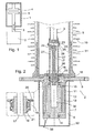
- FIG. 2 illustrates a first example of the actuating means 2 for a circuit breaker having a basic structure similar to that described with reference to Figure 1.
- the actuating means 2 comprises an electric motor 6 surrounded by a cover 7.
- the motor is suitably a three-phase permanent-magnet alternating-current motor.
- One end of the cover is secured to a mounting plate 8, suitably supported by a stand, by means of attachment bolts through holes in the plate 8.
- a hollow pillar 9 of insulating material, such as porcelain or plastic material, extends upwards in the figure from the side opposite to the motor.
- the insulation pillar 9 is provided externally with flanges 10 to provided an extended creepage distance.
- the actuating rod 3 is arranged inside the insulation pillar.
- the breaking chamber is also arranged in the upper end of the insulation pillar, not shown, and its movable contact is rigidly joined to the actuating rod 3.
- the actuating rod 3, insulation pillar 9 and motor are all coaxial with each other.
- the insulation pillar surrounds a space 31 enclosing the means for transmitting movement 3, 17 which transmits movement from the motor 6 to the movable contact 5 and which also comprises the actual breaking chamber 1.
- SF 6 gas is thus present in this chamber 31, termed the apparatus chamber in the present application.
- a conversion mechanism is arranged for converting rotary movement of the rotor 13 of the motor to translation movement of the actuating rod 3 in order to open or close the breaker as described with reference to Figure 1.
- the conversion mechanism will be described in more detail in the following.
- the rotor 13 is journalled in the motor housing 11 by means of a bearing 14, 15 at each end of the rotor.
- the stator 12 of the motor is secured to the motor housing 11 and the motor housing is secured to the mounting plate 8.
- the rotor 13 has a central boring 30 extending axially through most of its length.
- the mounting plate 8 has an opening coaxial with the motor shaft, in which a nut 16 is journalled for rotation in a double-operating angular contact ball bearing 18.
- the outer ring 19 of the bearing 18 is secured to the mounting plate 8 by means of bolts arranged in borings 20 through a flange on the outer ring.
- the inner ring 21 of the bearing 18 is also joined to the rotor 13 and unable to turn in relation thereto.
- a screw 17 extends through the nut, i.e. a rod provided with screw threading.
- the screw threads of the nut 16 and the screw 17 are in engagement with each other. Relative movement between them thus causes the screw to be displaced axially in relation to the nut.
- the screw 17 On its end facing away from the motor, i.e. the upper end in the figure, the screw 17 is connected to the actuating rod 3 of the breaker since the upper end of the screw extends in a boring 23 in the lower end 24 of the actuating rod 3.
- the connection is secured by means of a pin 25 extending diametrically through the ends of the screw and the operating rod.
- a guiding sleeve 26 surrounding the screw 17 extends from the mounting plate 8.
- the guiding sleeve is provided with axially running guides 27 arranged diametrically opposite each other.
- the pin 25 extends out through each guide 27 and is provided at each end with a locking washer 28.
- the width of the guides 27 corresponds to the diameter of the pin 25.
- the screw 17 is thus connected to the guiding sleeve 26 and unable to turn in relation thereto.
- the guiding sleeve 26 is also prevented from turning since it is secured to the mounting plate 8 by means of bolts through the borings 29.
- the guiding sleeve 26 has an inner diameter such that the actuating rod 3 can be inserted therein with little clearance.
- Figure 2 shows the actuating part of the circuit breaker when in its normal, closed position.
- the breaking process must occur extremely quickly. It is therefore necessary to have a high speed of rotation for the motor since the pitch of the screw must not be too great. Considerable acceleration and deceleration forces therefore also occur. It is therefore important that the mass of those components which are subjected to forces of inertia is as little as possible.
- the actuating rod 3 is therefore hollow.
- the screw has a number of thread entries. This permits large pitch of the threads without them being overloaded. Thus, with a pitch of 3 mm/turn a translation movement of 3 mm for each revolution of the motor is achieved for the breaker. With eight entries and correspondingly greater pitch the translation movement will be 24 mm/turn and with 12 entries it will be 36 mm/turn. With a stroke length of 120 mm for the breaking movement, 3.33 revolutions of the motor are required for the breaking movement in the case of 12 thread entries.
- the cover 7 surrounding the motor 6 constitutes a second gas-tight housing, thus forming a second gas-tight chamber 32 surrounding the motor 6.
- the cable 33 supplying the motor with current upon operation is passed through the cover 7 in gas-tight manner. Since the chamber 32 surrounding the motor is also gas-tight, no seal is required where the movement-transmitting means passes through the mounting plate 8. Power losses caused by sealing friction are thus eliminated.
- the movement-transmitting means shown in the figure is only intended as an example.
- the screw-nut arrangement may be vice versa, for instance, the screw being joined to the motor and the nut to the actuating rod 3 of the movable contact 5.
- This has the advantage that the moment of inertia to be accelerated by the motor will be less than in the embodiment illustrated.
- Many other mechanisms for converting the rotary movement of the motor to translation movement of the movable contact are naturally feasible within the scope of the invention.
- the invention is also applicable to a linear motor, in which case no conversion of the movement is necessary.
- the cable 33 supplying the motor with current is connected via a converter to a current source (not shown), such as capacitors, batteries or a power net, or a combination thereof.
- a current source such as capacitors, batteries or a power net, or a combination thereof.
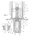
- FIG 3 shows a second embodiment of the breaker claimed.
- the design in Figure 3 differs from that in Figure 2 only in that the cover 7 which surrounds the motor is replaced with enclosure of only the rotor 13 of the motor, but is otherwise the same.
- the actual motor housing 11 is hermetically sealed to the mounting plate 8 by means of a connection rim 34.
- a lid 35 is sealingly secured to the motor housing 11.
- the rotor 13 will therefore be sealed inside a chamber formed by the mounting plate 8 connection rim 34, motor housing 11 and lid 35. No sealing out to the apparatus chamber 31 exists, as described with reference to the embodiment shown in Figure 2.
- the cable 33 supplying the motor with current is connected to a current source (not shown).
- FIG. 4 shows a third embodiment of the invention.
- the electric motor has been moved up inside the insulation pillar 9.
- the insulation pillar thus constitutes an aggregate housing surrounding the space 31 which is housed in the whole aggregate comprising contacts, actuating means and motor.
- the insulation pillar 9 must be extended by a distance corresponding to the length of the motor.
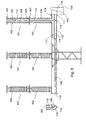
- FIG. 5 illustrates the invention as applied in a three-pole circuit breaker where the three breaker poles 101 are intended to be connected one to each phase of a three-phase transmission or distribution network.
- Each breaker pole 101 is filled with a breaker medium in the form of SF 6 gas and comprises a pin insulator 102 supporting a breaking chamber isolator 103.
- a stationary contact 104 and a movable contact 106 are provided in each breaking chamber isolator 103.
- the stationary contact 104 is connected to the electric network via a first connection flange 105.
- the movable contact 106 is also connected to the electric network, via a sliding contact 109 and a second connection flange 107.
- the breaker poles 101 are mounted on a hollow beam 108 so that the breaking medium can flow freely between the beam 108 and each breaker pole 101.
- a first end piece 110 and a second end piece 11 At each end of the beam 108, respectively, is a first end piece 110 and a second end piece 11, with tight sealing.
- the beam 108, end pieces 110, 111 and the three poles 101 thus constitute a common enclosure for all the breaker poles that surrounds a volume 112 filled with breaking medium.
- the movable contacts 106 are connected mechanically via a mechanical system to a motor 113 arranged on the short side of the beam 108.
- the motor 113 drives all three breaker poles 101 and influences a shaft 114 with a turning force.
- the mechanical system also comprises a coupling 115 for each breaker pole and an actuating rod 116.
- the shaft 114 runs inside the beam 108 in the longitudinal direction of the beam 108 and is there rotatably journalled in bearing brackets 117.
- the upper end of the actuating rod 116 is arranged at the movable contact 106.
- the rod 116 is arranged at the coupling 115 that converts a rotary movement of the shaft 114 to a translation movement of the rod 116.
- the majority of the mechanical system is thus located inside the enclosure and is thus protected from external influence, both mechanical (impact, etc.) and chemical (corrosion).
- the motor 113 is arranged in a space 119 which is hermetically sealed to the surroundings by a housing 120.
- the shaft 114 that is joined to the rotor of the motor 113 extends without sealing between the inner space 112 of the beam and the outer space 119 in which the motor 113 is arranged.
- the spaces 112 and 119 thus communicate with each other.
- Figure 6 shows an electric plant which includes part of an electrical switchgear station.
- An incoming cable 200 is connected to a busbar 202 via a transformer 206 and a first breaker 201.
- User cables 203 run from the busbar to respective loads 204 via respective breakers 205.
- Each of the breakers 201 and 205 is constructed in accordance with the circuit breaker according to the invention.
Landscapes
- Driving Mechanisms And Operating Circuits Of Arc-Extinguishing High-Tension Switches (AREA)
- Gas-Insulated Switchgears (AREA)
- Arc-Extinguishing Devices That Are Switches (AREA)
- Percussive Tools And Related Accessories (AREA)
- Valve Device For Special Equipments (AREA)
- Control Of Vending Devices And Auxiliary Devices For Vending Devices (AREA)
- Keying Circuit Devices (AREA)
Applications Claiming Priority (3)
| Application Number | Priority Date | Filing Date | Title |
|---|---|---|---|
| SE0003030 | 2000-08-28 | ||
| SE0003030A SE517028C2 (sv) | 2000-08-28 | 2000-08-28 | Elektrisk brytare, användning och förfarande samt en elektrisk anläggning innefattande en elektrisk brytare |
| PCT/SE2001/001819 WO2002019360A1 (en) | 2000-08-28 | 2001-08-27 | Circuit breaker |
Publications (2)
| Publication Number | Publication Date |
|---|---|
| EP1320860A1 EP1320860A1 (en) | 2003-06-25 |
| EP1320860B1 true EP1320860B1 (en) | 2007-07-18 |
Family
ID=20280802
Family Applications (1)
| Application Number | Title | Priority Date | Filing Date |
|---|---|---|---|
| EP01961538A Expired - Lifetime EP1320860B1 (en) | 2000-08-28 | 2001-08-27 | Circuit breaker |
Country Status (8)
| Country | Link |
|---|---|
| EP (1) | EP1320860B1 (OSRAM) |
| JP (1) | JP2004508789A (OSRAM) |
| CN (1) | CN1302498C (OSRAM) |
| AT (1) | ATE367643T1 (OSRAM) |
| AU (1) | AU2001282798A1 (OSRAM) |
| DE (1) | DE60129450T2 (OSRAM) |
| SE (1) | SE517028C2 (OSRAM) |
| WO (1) | WO2002019360A1 (OSRAM) |
Families Citing this family (4)
| Publication number | Priority date | Publication date | Assignee | Title |
|---|---|---|---|---|
| WO2004034550A1 (en) * | 2002-10-08 | 2004-04-22 | Stridsberg Innovation Ab | High axial force motor |
| EP2461338B2 (en) * | 2010-12-03 | 2017-03-01 | ABB Schweiz AG | Circuit breaker arrangement for medium voltage to high voltage applications |
| FR2969811B1 (fr) * | 2010-12-23 | 2013-02-08 | Areva T & D Sas | Dispositif a piston et cylindre pour appareillages electriques a moyenne et haute tension. |
| CN108565758B (zh) * | 2018-05-10 | 2024-03-26 | 河南森源电气股份有限公司 | 一种箱式变电站 |
Family Cites Families (5)
| Publication number | Priority date | Publication date | Assignee | Title |
|---|---|---|---|---|
| DE3224165A1 (de) * | 1982-06-29 | 1983-12-29 | Brown, Boveri & Cie Ag, 6800 Mannheim | Elektromagnetische vorrichtung zum antrieb eines gekapselten schaltgeraetes fuer mittelspannungs- oder hochspannungsschalt- und -verteileranlagen |
| CN2033942U (zh) * | 1988-07-15 | 1989-03-08 | 锦州新生开关厂 | 真空断路器 |
| IT1301872B1 (it) * | 1998-07-24 | 2000-07-07 | Abb Adda S P A | Dispositivo di comando e controllo di interruttori di alta e mediatensione |
| AU2554399A (en) * | 1998-12-16 | 2000-07-03 | Abb Ab | Operating device for driving and controlling an electrical switching apparatus |
| CN2389413Y (zh) * | 1999-08-31 | 2000-07-26 | 邯郸市恒丰电力电气设备有限公司 | 柱上多功能真空断路器 |
-
2000
- 2000-08-28 SE SE0003030A patent/SE517028C2/sv not_active IP Right Cessation
-
2001
- 2001-08-27 AT AT01961538T patent/ATE367643T1/de not_active IP Right Cessation
- 2001-08-27 CN CNB018181449A patent/CN1302498C/zh not_active Expired - Fee Related
- 2001-08-27 WO PCT/SE2001/001819 patent/WO2002019360A1/en not_active Ceased
- 2001-08-27 AU AU2001282798A patent/AU2001282798A1/en not_active Abandoned
- 2001-08-27 DE DE60129450T patent/DE60129450T2/de not_active Expired - Lifetime
- 2001-08-27 JP JP2002524169A patent/JP2004508789A/ja active Pending
- 2001-08-27 EP EP01961538A patent/EP1320860B1/en not_active Expired - Lifetime
Also Published As
| Publication number | Publication date |
|---|---|
| DE60129450T2 (de) | 2008-05-21 |
| SE0003030D0 (sv) | 2000-08-28 |
| ATE367643T1 (de) | 2007-08-15 |
| AU2001282798A1 (en) | 2002-03-13 |
| WO2002019360A1 (en) | 2002-03-07 |
| CN1302498C (zh) | 2007-02-28 |
| EP1320860A1 (en) | 2003-06-25 |
| SE517028C2 (sv) | 2002-04-02 |
| CN1471719A (zh) | 2004-01-28 |
| JP2004508789A (ja) | 2004-03-18 |
| SE0003030L (sv) | 2002-03-01 |
| DE60129450D1 (de) | 2007-08-30 |
Similar Documents
| Publication | Publication Date | Title |
|---|---|---|
| US6927355B2 (en) | Circuit breaker | |
| US7091439B2 (en) | Isolator/circuit-breaker device for electric substations | |
| US6759616B2 (en) | Gas insulated switchgear | |
| EP1826791B1 (en) | Three-position vacuum interrupter disconnect switch providing current interruption, disconnection and grounding | |
| TWI362151B (OSRAM) | ||
| CN104247184B (zh) | 开闭装置 | |
| KR101123916B1 (ko) | 회로 차단기 및/또는 접지 스위치를 위한 스핀들 구동부 | |
| KR101123915B1 (ko) | 차단 및/또는 접지 기능을 구비한 개폐 디바이스 | |
| JPH06335125A (ja) | 開閉装置 | |
| RU2418335C1 (ru) | Вакуумный выключатель | |
| CN1897376B (zh) | 真空绝缘开关设备 | |
| EP2645378B1 (en) | Electric device with insulators | |
| EP1320860B1 (en) | Circuit breaker | |
| KR101246696B1 (ko) | 접지 차단기 및 이의 제조 방법 | |
| RU2361345C2 (ru) | Распределительное устройство с элегазовой изоляцией | |
| EP3843117B1 (en) | Load-break switch without sf6 gas having a vacuum circuit interrupter for medium-voltage switching systems | |
| US7378759B2 (en) | Disconnecting switch assembly | |
| JP2012043664A (ja) | 開閉器,開閉器ユニット,スイッチギヤ及びスイッチギヤを搭載した風車 | |
| JP2000197221A (ja) | ガス絶縁3相密閉形開閉装置 | |
| US20240313512A1 (en) | Switchgear architecture | |
| RU2141710C1 (ru) | Комплектное распределительное устройство серии tel | |
| JPH05300616A (ja) | ガス封入配電盤 | |
| GB2628190A (en) | Switchgear architecture | |
| JP2016163499A (ja) | 開閉装置 | |
| CN121461156A (zh) | 一种高压金属封闭开关设备 |
Legal Events
| Date | Code | Title | Description |
|---|---|---|---|
| PUAI | Public reference made under article 153(3) epc to a published international application that has entered the european phase |
Free format text: ORIGINAL CODE: 0009012 |
|
| 17P | Request for examination filed |
Effective date: 20030327 |
|
| AK | Designated contracting states |
Designated state(s): AT BE CH CY DE DK ES FI FR GB GR IE IT LI LU MC NL PT SE TR |
|
| AX | Request for extension of the european patent |
Extension state: AL LT LV MK RO SI |
|
| RIN1 | Information on inventor provided before grant (corrected) |
Inventor name: HERMANSSON, LARS Inventor name: ROININEN, TOMAS Inventor name: THURESSON, PER OLOF Inventor name: VALDEMARSSON, STEFAN |
|
| GRAP | Despatch of communication of intention to grant a patent |
Free format text: ORIGINAL CODE: EPIDOSNIGR1 |
|
| GRAS | Grant fee paid |
Free format text: ORIGINAL CODE: EPIDOSNIGR3 |
|
| GRAA | (expected) grant |
Free format text: ORIGINAL CODE: 0009210 |
|
| AK | Designated contracting states |
Kind code of ref document: B1 Designated state(s): AT BE CH CY DE DK ES FI FR GB GR IE IT LI LU MC NL PT SE TR |
|
| REG | Reference to a national code |
Ref country code: GB Ref legal event code: FG4D |
|
| REG | Reference to a national code |
Ref country code: CH Ref legal event code: EP |
|
| REF | Corresponds to: |
Ref document number: 60129450 Country of ref document: DE Date of ref document: 20070830 Kind code of ref document: P |
|
| REG | Reference to a national code |
Ref country code: IE Ref legal event code: FG4D |
|
| REG | Reference to a national code |
Ref country code: CH Ref legal event code: NV Representative=s name: ISLER & PEDRAZZINI AG |
|
| ET | Fr: translation filed | ||
| PG25 | Lapsed in a contracting state [announced via postgrant information from national office to epo] |
Ref country code: FI Free format text: LAPSE BECAUSE OF FAILURE TO SUBMIT A TRANSLATION OF THE DESCRIPTION OR TO PAY THE FEE WITHIN THE PRESCRIBED TIME-LIMIT Effective date: 20070718 Ref country code: ES Free format text: LAPSE BECAUSE OF FAILURE TO SUBMIT A TRANSLATION OF THE DESCRIPTION OR TO PAY THE FEE WITHIN THE PRESCRIBED TIME-LIMIT Effective date: 20071029 Ref country code: PT Free format text: LAPSE BECAUSE OF FAILURE TO SUBMIT A TRANSLATION OF THE DESCRIPTION OR TO PAY THE FEE WITHIN THE PRESCRIBED TIME-LIMIT Effective date: 20071218 Ref country code: NL Free format text: LAPSE BECAUSE OF FAILURE TO SUBMIT A TRANSLATION OF THE DESCRIPTION OR TO PAY THE FEE WITHIN THE PRESCRIBED TIME-LIMIT Effective date: 20070718 |
|
| NLV1 | Nl: lapsed or annulled due to failure to fulfill the requirements of art. 29p and 29m of the patents act | ||
| PG25 | Lapsed in a contracting state [announced via postgrant information from national office to epo] |
Ref country code: AT Free format text: LAPSE BECAUSE OF FAILURE TO SUBMIT A TRANSLATION OF THE DESCRIPTION OR TO PAY THE FEE WITHIN THE PRESCRIBED TIME-LIMIT Effective date: 20070718 |
|
| PG25 | Lapsed in a contracting state [announced via postgrant information from national office to epo] |
Ref country code: BE Free format text: LAPSE BECAUSE OF FAILURE TO SUBMIT A TRANSLATION OF THE DESCRIPTION OR TO PAY THE FEE WITHIN THE PRESCRIBED TIME-LIMIT Effective date: 20070718 |
|
| PG25 | Lapsed in a contracting state [announced via postgrant information from national office to epo] |
Ref country code: MC Free format text: LAPSE BECAUSE OF NON-PAYMENT OF DUE FEES Effective date: 20070831 Ref country code: DK Free format text: LAPSE BECAUSE OF FAILURE TO SUBMIT A TRANSLATION OF THE DESCRIPTION OR TO PAY THE FEE WITHIN THE PRESCRIBED TIME-LIMIT Effective date: 20070718 Ref country code: GR Free format text: LAPSE BECAUSE OF FAILURE TO SUBMIT A TRANSLATION OF THE DESCRIPTION OR TO PAY THE FEE WITHIN THE PRESCRIBED TIME-LIMIT Effective date: 20071019 |
|
| PLBE | No opposition filed within time limit |
Free format text: ORIGINAL CODE: 0009261 |
|
| STAA | Information on the status of an ep patent application or granted ep patent |
Free format text: STATUS: NO OPPOSITION FILED WITHIN TIME LIMIT |
|
| 26N | No opposition filed |
Effective date: 20080421 |
|
| PG25 | Lapsed in a contracting state [announced via postgrant information from national office to epo] |
Ref country code: SE Free format text: LAPSE BECAUSE OF FAILURE TO SUBMIT A TRANSLATION OF THE DESCRIPTION OR TO PAY THE FEE WITHIN THE PRESCRIBED TIME-LIMIT Effective date: 20071018 |
|
| PG25 | Lapsed in a contracting state [announced via postgrant information from national office to epo] |
Ref country code: IE Free format text: LAPSE BECAUSE OF NON-PAYMENT OF DUE FEES Effective date: 20070827 |
|
| PG25 | Lapsed in a contracting state [announced via postgrant information from national office to epo] |
Ref country code: CY Free format text: LAPSE BECAUSE OF FAILURE TO SUBMIT A TRANSLATION OF THE DESCRIPTION OR TO PAY THE FEE WITHIN THE PRESCRIBED TIME-LIMIT Effective date: 20070718 |
|
| PG25 | Lapsed in a contracting state [announced via postgrant information from national office to epo] |
Ref country code: LU Free format text: LAPSE BECAUSE OF NON-PAYMENT OF DUE FEES Effective date: 20070827 |
|
| PG25 | Lapsed in a contracting state [announced via postgrant information from national office to epo] |
Ref country code: TR Free format text: LAPSE BECAUSE OF FAILURE TO SUBMIT A TRANSLATION OF THE DESCRIPTION OR TO PAY THE FEE WITHIN THE PRESCRIBED TIME-LIMIT Effective date: 20070718 |
|
| PGFP | Annual fee paid to national office [announced via postgrant information from national office to epo] |
Ref country code: FR Payment date: 20090814 Year of fee payment: 9 |
|
| PGFP | Annual fee paid to national office [announced via postgrant information from national office to epo] |
Ref country code: CH Payment date: 20090814 Year of fee payment: 9 Ref country code: DE Payment date: 20090821 Year of fee payment: 9 Ref country code: GB Payment date: 20090826 Year of fee payment: 9 |
|
| PGFP | Annual fee paid to national office [announced via postgrant information from national office to epo] |
Ref country code: IT Payment date: 20090820 Year of fee payment: 9 |
|
| REG | Reference to a national code |
Ref country code: CH Ref legal event code: PL |
|
| GBPC | Gb: european patent ceased through non-payment of renewal fee |
Effective date: 20100827 |
|
| PG25 | Lapsed in a contracting state [announced via postgrant information from national office to epo] |
Ref country code: CH Free format text: LAPSE BECAUSE OF NON-PAYMENT OF DUE FEES Effective date: 20100831 Ref country code: LI Free format text: LAPSE BECAUSE OF NON-PAYMENT OF DUE FEES Effective date: 20100831 |
|
| REG | Reference to a national code |
Ref country code: FR Ref legal event code: ST Effective date: 20110502 |
|
| PG25 | Lapsed in a contracting state [announced via postgrant information from national office to epo] |
Ref country code: IT Free format text: LAPSE BECAUSE OF NON-PAYMENT OF DUE FEES Effective date: 20100827 |
|
| REG | Reference to a national code |
Ref country code: DE Ref legal event code: R119 Ref document number: 60129450 Country of ref document: DE Effective date: 20110301 |
|
| PG25 | Lapsed in a contracting state [announced via postgrant information from national office to epo] |
Ref country code: FR Free format text: LAPSE BECAUSE OF NON-PAYMENT OF DUE FEES Effective date: 20100831 Ref country code: DE Free format text: LAPSE BECAUSE OF NON-PAYMENT OF DUE FEES Effective date: 20110301 |
|
| PG25 | Lapsed in a contracting state [announced via postgrant information from national office to epo] |
Ref country code: GB Free format text: LAPSE BECAUSE OF NON-PAYMENT OF DUE FEES Effective date: 20100827 |