EP1320192A1 - Surface acoustic wave filter device - Google Patents
Surface acoustic wave filter device Download PDFInfo
- Publication number
- EP1320192A1 EP1320192A1 EP01951955A EP01951955A EP1320192A1 EP 1320192 A1 EP1320192 A1 EP 1320192A1 EP 01951955 A EP01951955 A EP 01951955A EP 01951955 A EP01951955 A EP 01951955A EP 1320192 A1 EP1320192 A1 EP 1320192A1
- Authority
- EP
- European Patent Office
- Prior art keywords
- acoustic wave
- surface acoustic
- port
- wave filter
- elastic
- Prior art date
- Legal status (The legal status is an assumption and is not a legal conclusion. Google has not performed a legal analysis and makes no representation as to the accuracy of the status listed.)
- Withdrawn
Links
- 238000010897 surface acoustic wave method Methods 0.000 title claims abstract description 101
- 238000000034 method Methods 0.000 claims abstract description 12
- 239000000758 substrate Substances 0.000 claims description 12
- 238000010168 coupling process Methods 0.000 description 43
- 238000005859 coupling reaction Methods 0.000 description 43
- ATJFFYVFTNAWJD-UHFFFAOYSA-N Tin Chemical group [Sn] ATJFFYVFTNAWJD-UHFFFAOYSA-N 0.000 description 6
- 239000004411 aluminium Substances 0.000 description 6
- 229910052782 aluminium Inorganic materials 0.000 description 6
- XAGFODPZIPBFFR-UHFFFAOYSA-N aluminium Chemical compound [Al] XAGFODPZIPBFFR-UHFFFAOYSA-N 0.000 description 6
- 229910052751 metal Inorganic materials 0.000 description 6
- 239000002184 metal Substances 0.000 description 6
- 239000010409 thin film Substances 0.000 description 6
- 238000010586 diagram Methods 0.000 description 3
- 230000005540 biological transmission Effects 0.000 description 2
- 230000000694 effects Effects 0.000 description 2
- 238000010295 mobile communication Methods 0.000 description 2
- PNEYBMLMFCGWSK-UHFFFAOYSA-N Alumina Chemical compound [O-2].[O-2].[O-2].[Al+3].[Al+3] PNEYBMLMFCGWSK-UHFFFAOYSA-N 0.000 description 1
- 230000000903 blocking effect Effects 0.000 description 1
- 230000008878 coupling Effects 0.000 description 1
- 238000005530 etching Methods 0.000 description 1
- 230000008020 evaporation Effects 0.000 description 1
- 238000001704 evaporation Methods 0.000 description 1
- 239000011810 insulating material Substances 0.000 description 1
- 238000004519 manufacturing process Methods 0.000 description 1
- 230000001902 propagating effect Effects 0.000 description 1
Images






Classifications
-
- H—ELECTRICITY
- H03—ELECTRONIC CIRCUITRY
- H03H—IMPEDANCE NETWORKS, e.g. RESONANT CIRCUITS; RESONATORS
- H03H9/00—Networks comprising electromechanical or electro-acoustic elements; Electromechanical resonators
- H03H9/46—Filters
- H03H9/64—Filters using surface acoustic waves
-
- H—ELECTRICITY
- H03—ELECTRONIC CIRCUITRY
- H03H—IMPEDANCE NETWORKS, e.g. RESONANT CIRCUITS; RESONATORS
- H03H9/00—Networks comprising electromechanical or electro-acoustic elements; Electromechanical resonators
- H03H9/02—Details
- H03H9/125—Driving means, e.g. electrodes, coils
- H03H9/145—Driving means, e.g. electrodes, coils for networks using surface acoustic waves
- H03H9/14597—Matching SAW transducers to external electrical circuits
-
- H—ELECTRICITY
- H03—ELECTRONIC CIRCUITRY
- H03H—IMPEDANCE NETWORKS, e.g. RESONANT CIRCUITS; RESONATORS
- H03H9/00—Networks comprising electromechanical or electro-acoustic elements; Electromechanical resonators
- H03H9/02—Details
- H03H9/05—Holders or supports
- H03H9/10—Mounting in enclosures
- H03H9/1064—Mounting in enclosures for surface acoustic wave [SAW] devices
- H03H9/1071—Mounting in enclosures for surface acoustic wave [SAW] devices the enclosure being defined by a frame built on a substrate and a cap, the frame having no mechanical contact with the SAW device
-
- H—ELECTRICITY
- H03—ELECTRONIC CIRCUITRY
- H03H—IMPEDANCE NETWORKS, e.g. RESONANT CIRCUITS; RESONATORS
- H03H9/00—Networks comprising electromechanical or electro-acoustic elements; Electromechanical resonators
- H03H9/02—Details
- H03H9/05—Holders or supports
- H03H9/10—Mounting in enclosures
- H03H9/1064—Mounting in enclosures for surface acoustic wave [SAW] devices
- H03H9/1092—Mounting in enclosures for surface acoustic wave [SAW] devices the enclosure being defined by a cover cap mounted on an element forming part of the surface acoustic wave [SAW] device on the side of the IDT's
-
- H—ELECTRICITY
- H03—ELECTRONIC CIRCUITRY
- H03H—IMPEDANCE NETWORKS, e.g. RESONANT CIRCUITS; RESONATORS
- H03H9/00—Networks comprising electromechanical or electro-acoustic elements; Electromechanical resonators
- H03H9/25—Constructional features of resonators using surface acoustic waves
-
- H—ELECTRICITY
- H03—ELECTRONIC CIRCUITRY
- H03H—IMPEDANCE NETWORKS, e.g. RESONANT CIRCUITS; RESONATORS
- H03H9/00—Networks comprising electromechanical or electro-acoustic elements; Electromechanical resonators
- H03H9/46—Filters
- H03H9/64—Filters using surface acoustic waves
- H03H9/6423—Means for obtaining a particular transfer characteristic
- H03H9/6433—Coupled resonator filters
-
- H—ELECTRICITY
- H03—ELECTRONIC CIRCUITRY
- H03H—IMPEDANCE NETWORKS, e.g. RESONANT CIRCUITS; RESONATORS
- H03H9/00—Networks comprising electromechanical or electro-acoustic elements; Electromechanical resonators
- H03H9/46—Filters
- H03H9/64—Filters using surface acoustic waves
- H03H9/6423—Means for obtaining a particular transfer characteristic
- H03H9/6433—Coupled resonator filters
- H03H9/6436—Coupled resonator filters having one acoustic track only
-
- H—ELECTRICITY
- H03—ELECTRONIC CIRCUITRY
- H03H—IMPEDANCE NETWORKS, e.g. RESONANT CIRCUITS; RESONATORS
- H03H9/00—Networks comprising electromechanical or electro-acoustic elements; Electromechanical resonators
- H03H9/46—Filters
- H03H9/64—Filters using surface acoustic waves
- H03H9/6423—Means for obtaining a particular transfer characteristic
- H03H9/6433—Coupled resonator filters
- H03H9/644—Coupled resonator filters having two acoustic tracks
- H03H9/6456—Coupled resonator filters having two acoustic tracks being electrically coupled
- H03H9/6469—Coupled resonator filters having two acoustic tracks being electrically coupled via two connecting electrodes
- H03H9/6473—Coupled resonator filters having two acoustic tracks being electrically coupled via two connecting electrodes the electrodes being electrically interconnected
Definitions
- This invention relates to an surface acoustic wave filter device where an elastic surface element and a housing are assembled particularly by face down bonding techniques.
- surface acoustic wave filter devices are compact and light and have a high performance and high reliability in terms of functions, so that they have been widely used in various fields.
- Two-way transmission filters for mobile communication are required to present high attenuation characteristics to the frequency blocking regions in their frequency characteristics.
- One two-way transmission filter is so constructed that a plurality of inter-digital transducers (hereinafter, referred to as IDTs) are arranged in the direction in which elastic surface waves propagate and mode-coupling two-port surface acoustic wave filters using the multiple resonance mode are connected in a multistage manner (an surface acoustic wave filter device).
- IDTs inter-digital transducers
- a method of connecting a one-port resonator in series with mode-coupling two-port surface acoustic wave filters can be considered.
- the one-port resonator is used as a notch filter.
- the attenuation pole of the one-port resonator is set near the high-pass region of the frequency pass band of the mode-coupling two-port surface acoustic wave filters, the entire frequency characteristic presents a sharp cut-off characteristic in the high-frequency region.
- the inventors of the present invention directed their attention to the fact that the addition of a one-port resonator causes a new problem.
- the inventors concentrated their attention on the fact that the problem particularly arises in an surface acoustic wave filter device where component parts are assembled by face down bonding techniques.
- the notch characteristic of the one-port resonator cannot be obtained in the desired frequency region as designed, with the result that the entire frequency pass band characteristic of an surface acoustic wave filter device superior in quality cannot be obtained.
- Another object of the present invention is to provide an surface acoustic wave filter device which enables unnecessary stray capacitance components in a one-port resonator to be reduced sufficiently and realizes a frequency pass band characteristic excellent in flatness.
- an embodiment of the present invention is configured as follows.
- the elastic surface wave element has a first two-port surface acoustic wave filter, a one-port elastic surface wave resonator filter to which the output of the first surface acoustic wave filter is supplied, a second two-port surface acoustic wave filter to which the output of the one-port elastic surface wave resonator filter is supplied, elastic-surface-wave-element side signal input and output electrodes, and an elastic-surface-wave-element side ground electrode each formed on one face of a piezoelectric substrate.
- the housing has signal input and output electrodes corresponding to the elastic-surface-wave-element side signal input and output electrodes and the elastic-surface-wave-element side ground electrode, the ground electrode having an opening section facing the one-port elastic surface wave resonator filter.
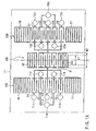
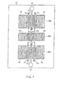
- FIG. 1A numeral 11 indicates a piezoelectric substrate.
- FIG. 1A is a plan view of the piezoelectric substrate 11 looking down on the side where an inter-digital transducer is formed.
- mode-coupling two-port surface acoustic wave filters 100, 200 are formed with a spacing between them.
- the mode-coupling two-port surface acoustic wave filters 100, 200 are made of a metal thin film, such as aluminium (Al), by manufacturing techniques, such as etching or evaporation.
- the mode-coupling two-port surface acoustic wave filter 100 is composed of five IDTs (Inter-Digital Transducers) 11, 12, 13, 14, 15 provided side by side and reflectors 16, 17 provided on both sides of these IDTs 11 to 15.
- IDTs Inter-Digital Transducers
- an IDT is composed of a pair of comb-tooth-like electrodes crossing each other in such a manner that they are staggered.
- the one-end-side comb-tooth-like electrodes of the IDTs 11, 13, 15 are connected to ground terminals T11, T13, T15, respectively.
- the other-end-side comb-tooth-like electrodes of the IDTs 11, 13, 15 are connected together and further connected to one electrode of an elastic surface wave resonator filter 300 explained later.
- the one-end-side comb-tooth-like electrodes of the IDTs 12, 14 are connected in common to an input terminal TIN and the other-end-side comb-tooth-like electrodes are connected to ground terminals T12, T14, respectively.
- This filter is composed of five IDTs 21, 22, 23, 24, 25 provided side by side and reflectors 26, 27 provided on both sides of the IDTs 21 to 25.
- the one-end-side comb-tooth-like electrodes of the IDTs 21, 23, 25 are connected to ground terminals T21, T23, T25, respectively.
- the other-end-side comb-tooth-like electrodes of the IDTs 21, 23, 25 are connected together and further connected to the other electrode of the elastic surface wave resonator filter 300 explained later.
- the one-end-side comb-tooth-like electrodes of the IDTs 22, 24 are connected in common to an output terminal TOU and the other-end-side comb-tooth-like electrodes are connected to ground terminals T22, T24, respectively.
- This filter is composed of an IDT 31 and reflector 32, 33 provided on both sides of the IDT 31.
- port means a pair of input and output terminals.
- input and output terminals are considered in terms of an equivalent circuit and the number of input and output terminals is not necessarily equal to the number of terminals in the actual configuration.
- the terminal TIN of the filter 100 and the wire to which three strip lines are joined and which is connected to the filter 300 make a pair and the terminals T11, T13, T15 and the terminals T12, T14 make a pair, which constructs a 2-port filter.
- the pass band is obtained by coupling first-degree, third-degree, and fifth-degree longitudinal resonance modes.
- the elastic surface wave resonator filter 300 has the following function.
- the mode-coupling two-port surface acoustic wave filters 100, 200 each function as a band-pass filter, but their frequency characteristics present insufficient attenuation characteristics on the high-pass region of the pass band.
- a one-port elastic surface wave resonator filter 300 functioning as a notch filter is formed between the two filters 100, 200 and used together with the two filters 100, 200.
- the attenuation pole of the resonator filter 300 is set near the high-pass region of the frequency pass band of the mode-coupling two-port surface acoustic wave filter. This enables the high-frequency region of the entire frequency characteristic to present a sharp cut-off characteristic. This invention can achieve such performance sufficiently.
- numeral 500 indicates a housing formed from, for example, an alumina ceramic substrate. On its periphery, a frame 501 is provided. That is, the housing 500 is formed into almost a flat plate made of insulating material.
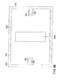
- FIG. 1B is a plan view of the housing 500 taken from above.
- ground terminal electrodes 503, 504 On the opposite face of the housing 500 to the elastic surface wave element, ground terminal electrodes 503, 504, and an input terminal electrode 506 and an output terminal electrode 507 corresponding to the input terminal TIN and output terminal TOU, respectively, are formed. Between the ground terminal electrodes 503, 504, a gap (or an opening) 505 is formed. The gap 505 is in a position where it faces the elastic surface wave resonator filter 300. Therefore, the ground terminal electrodes can be considered to have their portions facing the elastic surface wave resonator filter 300 removed. Alternately, the ground terminal electrodes can be considered to have been divided into the mode-coupling two-port surface acoustic wave filter 100 side and the mode-coupling two-port surface acoustic wave filter 200 side.
- the width W1 of the gap 505 is greater than the width W2 of the elastic surface wave resonator filter 300 (or the opening L1 of IDT) (W1 ⁇ W2).
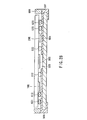
- FIG. 2A is a view, taken from above, of the elastic surface wave element of FIG. 1A mounted on the housing 500 by face down bonding techniques.
- FIG. 2B is a sectional view of FIG. 2A.
- the ground terminals T11, T13, T15 are connected to the ground terminal electrode 503 via bumps and the ground terminals T21, T23, T25 are connected to the ground terminal electrode 504 via bumps.
- the input terminal TIN is connected to the input terminal electrode 506 via a bump
- the output terminal TOU is connected to the output electrode 507 via a bump.
- a bump 601 between the input terminal TIN and the input terminal electrode 506 and a bump 602 between the output terminal TOU and the output terminal electrode 507 appear.
- bumps 613, 612 between the terminals T13 and T12 and the electrode 503 appear.
- bumps 623, 622 between the terminals T23 and T22 and the electrode 504 appear.
- a cap is provided on the top of the housing 500 and the filter section is sealed.
- the mode-coupling two-port surface acoustic wave filter 100 when an input signal is supplied to the input terminal electrode 506, resonance occurs in the mode-coupling two-port surface acoustic wave filter 100.
- the output signal of the surface acoustic wave filter 100 is input to the elastic surface wave resonator filter 300.
- the output signal of the resonator filter 300 is input to the mode-coupling two-port surface acoustic wave filter 200.
- the output of the mode-coupling two-port surface acoustic wave filter 200 is taken out from the output terminal electrode 507.
- a gap (or an opening) 505 is formed between the ground terminal electrodes 503, 504.
- the gap 505 is in a position where it faces the one-port elastic surface wave resonator filter 300. This enables a stray capacitance added to the elastic surface wave resonator filter 300 to be reduced sufficiently. As a result, the frequency characteristic of the elastic surface wave resonator filter 300 (or the characteristic of the notch filter) is achieved sufficiently as designed.
- the attenuation pole of the elastic surface wave resonator filter 300 is set reliably near the high-pass region of the frequency pass band of the mode-coupling two-port surface acoustic wave filter. Consequently, the frequency characteristic of the entire device is flat, with a sharp cut-off characteristic in the high-frequency region.
- the elastic surface wave element has been simplified. Actually, however, 100 IDTs may be provided.
- the opening L1 of an IDT (see FIG. 1A) is in the range of 80 to 100 microns.
- the width W1 of the gap 505 is selected from the range of 10 to 200 microns.
- FIG. 3 shows frequency characteristics of the elastic surface wave resonator filter 300.
- the ordinate indicates the amount of attenuation and the abscissa indicates the frequency.
- the characteristic curve 3A shows a characteristic when an opening section is provided in the ground electrode and the characteristic curve 3B shows a characteristic when no opening section is provided. It can be seen that the characteristic shown by the characteristic curve 3A changes sharply near 962.5 MHz.
- FIG. 4 shows a frequency characteristic of the entire surface acoustic wave filter device. This is the frequency characteristic of the resonator filter (or notch filter) 300, with no opening section in the ground electrode.
- the ordinate at left indicates the amount of attenuation, being graduated in units of 10 dB and in units of 1 dB.
- the abscissa indicates the frequency.
- the characteristic curve 4A represents the frequency characteristic of the entire device on a scale in units of 10 dB.
- the characteristic curve 4B represents the frequency characteristic of the entire device on a scale in units of 1 dB.
- FIG. 5 shows a frequency characteristic of the entire surface acoustic wave filter device. This frequency characteristic is the characteristic (or the characteristic of the device related to the invention) when an opening section is made in the ground electrode.
- the ordinate at left indicates the amount of attenuation, being graduated in units of 10 dB and in units of 1 dB.
- the abscissa indicates the frequency.
- the characteristic curve 5A represents the frequency characteristic of the entire device on a scale in units of 10 dB.
- the characteristic curve 5B represents the frequency characteristic of the entire device on a scale in units of 1 dB.
- the pass band shows a flat characteristic.
- This invention is not limited to the above embodiment.
- FIG. 6A shows another example of the housing 500 used in an surface acoustic wave filter device according to the present invention.
- the width W1 of the gap 505 is set greater than the width W2 of the elastic surface wave resonator filter 300 (or the opening L1 of IDT) (W1 ⁇ W2).
- the width W1 of the gap 505 is designed to be smaller than the width W2 of the elastic surface wave resonator filter 300 (or the opening L1 of IDT). This configuration also produces the effect aimed at in this invention.
- FIG. 6B shows still another example of the housing 500 used in an surface acoustic wave filter device according to the present invention.
- the gap (or opening section) 505 is formed from the top end to the bottom end.
- an opening section 505a is formed by making a rectangular opening in part of the base 502. Forming such an opening section 505a so as to face the area of the elastic surface wave resonator filter 300 enables the stray capacitance in the filter 300 to be reduced.
- the relationship between the width of the opening section 505a and the width of the filter 300 may be as shown in FIG. 1B or as shown in FIG. 6A. That is, the width W1 may be smaller than ( ⁇ W2) or larger than (> W2) the filter width W2 in the direction perpendicular to the direction in which the elastic surface wave from the elastic surface wave resonator filter 300 propagates.
- the mode-coupling two-port surface acoustic wave filters are not necessarily of the type explained in the above embodiments.
- the elastic surface wave resonator filter 300 has been connected in series with the mode-coupling two-port surface acoustic wave filters 100, 200.
- the elastic surface wave resonator filter 300 may be connected in parallel with the mode-coupling two-port surface acoustic wave filters 100, 200.
- the mode-coupling two-port surface acoustic wave filters 100, 200 may have the same frequency characteristic or differ from each other in frequency characteristic.
- two mode-coupling two-port surface acoustic wave filters 100, 200 and an elastic surface wave resonator filter 300 connected in series with the mode-coupling two-port surface acoustic wave filters 100, 200 are formed from a metal thin film, such as aluminium (Al).
- the mode-coupling two-port surface acoustic wave filter 100 is composed of three IDTs 1a, 1b, 1c provided side by side, reflectors 1e, 1f provided on both sides of the IDTs 1a, 1b 1c, and a terminal electrode 1g connected to a comb-tooth-like electrode constituting the IDT 1b.
- the mode-coupling two-port surface acoustic wave filter 200 is composed of three IDTs 2a, 2b, 2c provided side by side, reflectors 2d, 2e provided on both sides of the IDTs 2a, 2b, 2c, and a terminal electrode 2f connected to a comb-tooth-like electrode constituting the IDT 2b.
- the elastic surface wave resonator filter 300 is composed of an IDT 3a and reflectors 3b, 3c provided on both sides of the IDT 3a.
- two mode-coupling two-port surface acoustic wave filters 100, 200 and an elastic surface wave resonator filter 300 connected in parallel with the mode-coupling two-port surface acoustic wave filters 100, 200 are formed from a metal thin film, such as aluminium (Al).
- the mode-coupling two-port surface acoustic wave filters 100, 200 have the same configuration as shown in FIG. 7.
- the elastic surface wave resonator filter 300 has the same configuration as shown in FIG. 7. However, the example shown in FIG. 8 differs from that of FIG. 7 in the position where the elastic surface wave resonator filter 300 is provided.
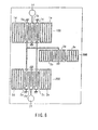
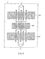
- FIGS. 9, 10, and 11 show still other embodiments of an surface acoustic wave filter element.
- two mode-coupling two-port surface acoustic wave filters 100, 200 and an elastic surface wave resonator filter 300 connected in series with the mode-coupling two-port surface acoustic wave filters 100, 200 are formed from a metal thin film, such as aluminium (Al).
- the mode-coupling two-port surface acoustic wave filter 100 is composed of five IDTs provided side by side, reflectors provided on both sides of the IDTs, and a terminal electrode 1f serving as a signal input section.
- the mode-coupling two-port surface acoustic wave filter 200 is composed of five IDTs provided side by side, reflectors provided on both sides of the IDTs, and a terminal electrode.
- the elastic surface wave resonator filter 300 is composed of an IDT, reflectors provided on both sides of the IDT, and a terminal electrode 2f serving as a signal output section.
- two mode-coupling two-port surface acoustic wave filters 100, 200 and an elastic surface wave resonator filter 300 connected in series with the mode-coupling two-port surface acoustic wave filters 100, 200 are formed from a metal thin film, such as aluminium (Al).
- the mode-coupling two-port surface acoustic wave filter 100 is composed of seven IDTs provided side by side, reflectors provided on both sides of the IDTs, and a terminal electrode 1f serving as a signal input section.
- the mode-coupling two-port surface acoustic wave filter 200 is composed of seven IDTs provided side by side, reflectors provided on both sides of the IDTs, and a terminal electrode 2f serving as a signal output terminal.
- the elastic surface wave resonator filter 300 is composed of an IDT and reflectors provided on both sides of the IDT.
- two mode-coupling two-port surface acoustic wave filters 100, 200 and an elastic surface wave resonator filter 300 connected in series with the mode-coupling two-port surface acoustic wave filters 100, 200 are formed from a metal thin film, such as aluminium (Al).
- the mode-coupling two-port surface acoustic wave filter 100 is composed of three IDTs provided side by side, reflectors provided on both sides of the IDTs, and a terminal electrode 1f serving as a signal input section.
- the mode-coupling two-port surface acoustic wave filter 200 is composed of seven IDTs provided side by side, reflectors provided on both sides of the IDTs, and a terminal electrode 2f serving as a signal output terminal.
- the elastic surface wave resonator filter 300 is composed of an IDT and reflectors provided on both sides of the IDT.
- the ground terminal electrode corresponding to the elastic surface wave resonator filter has only to be removed.
- An surface acoustic wave filter device can be used in the field of electronic apparatuses, including mobile communications equipment and television sets.
Landscapes
- Physics & Mathematics (AREA)
- Acoustics & Sound (AREA)
- Surface Acoustic Wave Elements And Circuit Networks Thereof (AREA)
Abstract
In an elastic surface wave device according
to this invention, an elastic surface wave element
including a first and a second two-port surface
acoustic wave filter (100, 200) and a one-port surface
acoustic wave filter (300) with a single inter-digital
transducer is connected via bumps to electrodes formed
on a housing (500) by face down bonding techniques.
The housing (500) has an opening section for a ground
terminal electrode in a part facing the one-port
surface acoustic wave filter (300).
Description
This invention relates to an surface acoustic wave
filter device where an elastic surface element and
a housing are assembled particularly by face down
bonding techniques.
As is generally known, surface acoustic wave
filter devices are compact and light and have a high
performance and high reliability in terms of functions,
so that they have been widely used in various fields.
Two-way transmission filters for mobile
communication are required to present high attenuation
characteristics to the frequency blocking regions in
their frequency characteristics. One two-way
transmission filter is so constructed that a plurality
of inter-digital transducers (hereinafter, referred to
as IDTs) are arranged in the direction in which elastic
surface waves propagate and mode-coupling two-port
surface acoustic wave filters using the multiple
resonance mode are connected in a multistage manner
(an surface acoustic wave filter device).
To improve the frequency characteristic of surface
acoustic wave filter device more, a method of
connecting a one-port resonator in series with mode-coupling
two-port surface acoustic wave filters can be
considered.
In this case, the one-port resonator is used as
a notch filter. When the attenuation pole of the
one-port resonator is set near the high-pass region of
the frequency pass band of the mode-coupling two-port
surface acoustic wave filters, the entire frequency
characteristic presents a sharp cut-off characteristic
in the high-frequency region.
Here, the inventors of the present invention
directed their attention to the fact that the addition
of a one-port resonator causes a new problem. The
inventors concentrated their attention on the fact that
the problem particularly arises in an surface acoustic
wave filter device where component parts are assembled
by face down bonding techniques. In an surface
acoustic wave filter device using face down bonding
techniques, the notch characteristic of the one-port
resonator cannot be obtained in the desired frequency
region as designed, with the result that the entire
frequency pass band characteristic of an surface
acoustic wave filter device superior in quality cannot
be obtained.
It is accordingly an object of the present
invention to provide an surface acoustic wave filter
device which enables the notch characteristic of a
one-port resonator to be obtained reliably near the
high-pass region of the frequency pass band of a
mode-coupling two-port surface acoustic wave filter,
even when component parts are assembled by face down
bonding techniques.
Another object of the present invention is to
provide an surface acoustic wave filter device which
enables unnecessary stray capacitance components in
a one-port resonator to be reduced sufficiently and
realizes a frequency pass band characteristic excellent
in flatness.
To accomplish the foregoing objects, an embodiment
of the present invention is configured as follows.
In an surface acoustic wave filter device where the
electrodes of an elastic surface wave element are
connected via bumps to the electrodes of a housing
by face down bonding techniques, the elastic surface
wave element has a first two-port surface acoustic wave
filter, a one-port elastic surface wave resonator
filter to which the output of the first surface
acoustic wave filter is supplied, a second two-port
surface acoustic wave filter to which the output of the
one-port elastic surface wave resonator filter is
supplied, elastic-surface-wave-element side signal
input and output electrodes, and an elastic-surface-wave-element
side ground electrode each formed on one
face of a piezoelectric substrate. In addition, the
housing has signal input and output electrodes
corresponding to the elastic-surface-wave-element side
signal input and output electrodes and the elastic-surface-wave-element
side ground electrode, the ground
electrode having an opening section facing the one-port
elastic surface wave resonator filter.
Hereinafter, referring to the accompanying
drawings, embodiments of the present invention will be
explained.
In FIG. 1A, numeral 11 indicates a piezoelectric
substrate. FIG. 1A is a plan view of the piezoelectric
substrate 11 looking down on the side where an inter-digital
transducer is formed. At the right and left
sides of the piezoelectric substrate 11, mode-coupling
two-port surface acoustic wave filters 100, 200 are
formed with a spacing between them. The mode-coupling
two-port surface acoustic wave filters 100, 200 are
made of a metal thin film, such as aluminium (Al),
by manufacturing techniques, such as etching or
evaporation.
The mode-coupling two-port surface acoustic wave
filter 100 is composed of five IDTs (Inter-Digital
Transducers) 11, 12, 13, 14, 15 provided side by side
and reflectors 16, 17 provided on both sides of these
IDTs 11 to 15. As is generally known, an IDT is
composed of a pair of comb-tooth-like electrodes
crossing each other in such a manner that they are
staggered.
The one-end-side comb-tooth-like electrodes of the
IDTs 11, 13, 15 are connected to ground terminals T11,
T13, T15, respectively. The other-end-side comb-tooth-like
electrodes of the IDTs 11, 13, 15 are connected
together and further connected to one electrode of an
elastic surface wave resonator filter 300 explained
later. The one-end-side comb-tooth-like electrodes of
the IDTs 12, 14 are connected in common to an input
terminal TIN and the other-end-side comb-tooth-like
electrodes are connected to ground terminals T12, T14,
respectively.
Next, the mode-coupling two-port surface acoustic
wave filter 200 will be explained. This filter is
composed of five IDTs 21, 22, 23, 24, 25 provided side
by side and reflectors 26, 27 provided on both sides of
the IDTs 21 to 25. The one-end-side comb-tooth-like
electrodes of the IDTs 21, 23, 25 are connected to
ground terminals T21, T23, T25, respectively. The
other-end-side comb-tooth-like electrodes of the IDTs
21, 23, 25 are connected together and further connected
to the other electrode of the elastic surface wave
resonator filter 300 explained later. The one-end-side
comb-tooth-like electrodes of the IDTs 22, 24 are
connected in common to an output terminal TOU and the
other-end-side comb-tooth-like electrodes are connected
to ground terminals T22, T24, respectively.
Next, the one-port elastic surface wave resonator
filter 300 will be explained. This filter is composed
of an IDT 31 and reflector 32, 33 provided on both
sides of the IDT 31.
In the present invention, "port" means a pair of
input and output terminals. Here, input and output
terminals are considered in terms of an equivalent
circuit and the number of input and output terminals is
not necessarily equal to the number of terminals in the
actual configuration. For example, the terminal TIN of
the filter 100 and the wire to which three strip lines
are joined and which is connected to the filter 300
make a pair and the terminals T11, T13, T15 and the
terminals T12, T14 make a pair, which constructs a
2-port filter.
In the mode-coupling two-port surface acoustic
wave filters 100, 200, five IDTs are arranged along
the elastic surface wave propagating path of the
piezoelectric substrate as shown in the figure. As is
generally known, the pass band is obtained by coupling
first-degree, third-degree, and fifth-degree
longitudinal resonance modes.
In the elastic surface wave element 11 where the
mode-coupling two-port surface acoustic wave filters
have been formed as described above, the elastic
surface wave resonator filter 300 has the following
function.
The mode-coupling two-port surface acoustic wave
filters 100, 200 each function as a band-pass filter,
but their frequency characteristics present
insufficient attenuation characteristics on the
high-pass region of the pass band. To overcome this
drawback, a one-port elastic surface wave resonator
filter 300 functioning as a notch filter is formed
between the two filters 100, 200 and used together
with the two filters 100, 200. The attenuation pole of
the resonator filter 300 is set near the high-pass
region of the frequency pass band of the mode-coupling
two-port surface acoustic wave filter. This enables
the high-frequency region of the entire frequency
characteristic to present a sharp cut-off
characteristic. This invention can achieve such
performance sufficiently.
The reason for this is clarified in an explanation
of FIG. 1B and FIGS. 2A and 2B.
In FIG. 1B, numeral 500 indicates a housing formed
from, for example, an alumina ceramic substrate.
On its periphery, a frame 501 is provided. That is,
the housing 500 is formed into almost a flat plate made
of insulating material. FIG. 1B is a plan view of the
housing 500 taken from above.
On the opposite face of the housing 500 to
the elastic surface wave element, ground terminal
electrodes 503, 504, and an input terminal electrode
506 and an output terminal electrode 507 corresponding
to the input terminal TIN and output terminal TOU,
respectively, are formed. Between the ground terminal
electrodes 503, 504, a gap (or an opening) 505 is
formed. The gap 505 is in a position where it faces
the elastic surface wave resonator filter 300.
Therefore, the ground terminal electrodes can be
considered to have their portions facing the
elastic surface wave resonator filter 300 removed.
Alternately, the ground terminal electrodes can be
considered to have been divided into the mode-coupling
two-port surface acoustic wave filter 100 side and the
mode-coupling two-port surface acoustic wave filter 200
side.
In this embodiment, the width W1 of the gap 505
is greater than the width W2 of the elastic surface
wave resonator filter 300 (or the opening L1 of IDT)
(W1 < W2).
The input terminal electrode 506 and output
terminal electrode 507 corresponding to the input
terminal TIN and output terminal TOU, respectively,
are formed.
FIG. 2A is a view, taken from above, of the
elastic surface wave element of FIG. 1A mounted on the
housing 500 by face down bonding techniques. FIG. 2B
is a sectional view of FIG. 2A.
The ground terminals T11, T13, T15 are connected
to the ground terminal electrode 503 via bumps and the
ground terminals T21, T23, T25 are connected to the
ground terminal electrode 504 via bumps. The input
terminal TIN is connected to the input terminal
electrode 506 via a bump, and the output terminal TOU
is connected to the output electrode 507 via a bump.
In FIG. 2B, a bump 601 between the input terminal TIN
and the input terminal electrode 506 and a bump 602
between the output terminal TOU and the output terminal
electrode 507 appear. Moreover, bumps 613, 612 between
the terminals T13 and T12 and the electrode 503 appear.
In addition, bumps 623, 622 between the terminals T23
and T22 and the electrode 504 appear.
Although not shown, a cap is provided on the top
of the housing 500 and the filter section is sealed.
In the surface acoustic wave filter device, when
an input signal is supplied to the input terminal
electrode 506, resonance occurs in the mode-coupling
two-port surface acoustic wave filter 100. The output
signal of the surface acoustic wave filter 100 is input
to the elastic surface wave resonator filter 300.
The output signal of the resonator filter 300 is input
to the mode-coupling two-port surface acoustic wave
filter 200. The output of the mode-coupling two-port
surface acoustic wave filter 200 is taken out from the
output terminal electrode 507.
Between the ground terminal electrodes 503, 504,
a gap (or an opening) 505 is formed. The gap 505 is in
a position where it faces the one-port elastic surface
wave resonator filter 300. This enables a stray
capacitance added to the elastic surface wave resonator
filter 300 to be reduced sufficiently. As a result,
the frequency characteristic of the elastic surface
wave resonator filter 300 (or the characteristic of
the notch filter) is achieved sufficiently as designed.
The attenuation pole of the elastic surface wave
resonator filter 300 is set reliably near the high-pass
region of the frequency pass band of the mode-coupling
two-port surface acoustic wave filter. Consequently,
the frequency characteristic of the entire device is
flat, with a sharp cut-off characteristic in the
high-frequency region.
In the explanation, to make it easy to understand
the configuration, the elastic surface wave element has
been simplified. Actually, however, 100 IDTs may be
provided. The opening L1 of an IDT (see FIG. 1A) is
in the range of 80 to 100 microns. The width W1 of
the gap 505 is selected from the range of 10 to
200 microns.
Next, the result of measuring the frequency
characteristics and other characteristics of the
surface acoustic wave filter device according to the
present invention will be explained.
FIG. 3 shows frequency characteristics of the
elastic surface wave resonator filter 300. The
ordinate indicates the amount of attenuation and the
abscissa indicates the frequency. The characteristic
curve 3A shows a characteristic when an opening
section is provided in the ground electrode and the
characteristic curve 3B shows a characteristic when no
opening section is provided. It can be seen that the
characteristic shown by the characteristic curve 3A
changes sharply near 962.5 MHz.
FIG. 4 shows a frequency characteristic of the
entire surface acoustic wave filter device. This is
the frequency characteristic of the resonator filter
(or notch filter) 300, with no opening section in the
ground electrode.
The ordinate at left indicates the amount of
attenuation, being graduated in units of 10 dB and in
units of 1 dB. The abscissa indicates the frequency.
In FIG. 4, the characteristic curve 4A represents the
frequency characteristic of the entire device on a
scale in units of 10 dB. The characteristic curve 4B
represents the frequency characteristic of the entire
device on a scale in units of 1 dB.
FIG. 5 shows a frequency characteristic of the
entire surface acoustic wave filter device. This
frequency characteristic is the characteristic (or the
characteristic of the device related to the invention)
when an opening section is made in the ground
electrode.
The ordinate at left indicates the amount of
attenuation, being graduated in units of 10 dB and in
units of 1 dB. The abscissa indicates the frequency.
In FIG. 5, the characteristic curve 5A represents
the frequency characteristic of the entire device on
a scale in units of 10 dB. The characteristic curve 5B
represents the frequency characteristic of the entire
device on a scale in units of 1 dB.
As seen from the comparison of the frequency
characteristic with that of FIG. 4, the pass band shows
a flat characteristic.
This invention is not limited to the above
embodiment.
FIG. 6A shows another example of the housing 500
used in an surface acoustic wave filter device
according to the present invention. In the above
embodiment, the width W1 of the gap 505 is set greater
than the width W2 of the elastic surface wave resonator
filter 300 (or the opening L1 of IDT) (W1 < W2). In
the embodiment of FIG. 6A, however, the width W1 of the
gap 505 is designed to be smaller than the width W2 of
the elastic surface wave resonator filter 300 (or the
opening L1 of IDT). This configuration also produces
the effect aimed at in this invention.
FIG. 6B shows still another example of the housing
500 used in an surface acoustic wave filter device
according to the present invention. In the above
embodiments, the gap (or opening section) 505 is formed
from the top end to the bottom end. In the embodiment
of FIG. 6B, an opening section 505a is formed by making
a rectangular opening in part of the base 502. Forming
such an opening section 505a so as to face the area of
the elastic surface wave resonator filter 300 enables
the stray capacitance in the filter 300 to be reduced.
The relationship between the width of the opening
section 505a and the width of the filter 300 may be
as shown in FIG. 1B or as shown in FIG. 6A. That is,
the width W1 may be smaller than (< W2) or larger
than (> W2) the filter width W2 in the direction
perpendicular to the direction in which the elastic
surface wave from the elastic surface wave resonator
filter 300 propagates.
In this invention, the mode-coupling two-port
surface acoustic wave filters are not necessarily of
the type explained in the above embodiments. In the
embodiments, the elastic surface wave resonator filter
300 has been connected in series with the mode-coupling
two-port surface acoustic wave filters 100, 200.
In contrast, as shown in FIGS. 7 and 8, the elastic
surface wave resonator filter 300 may be connected
in parallel with the mode-coupling two-port surface
acoustic wave filters 100, 200. The mode-coupling
two-port surface acoustic wave filters 100, 200 may
have the same frequency characteristic or differ from
each other in frequency characteristic.
First, in FIG. 7, on a piezoelectric substrate 11,
two mode-coupling two-port surface acoustic wave
filters 100, 200 and an elastic surface wave resonator
filter 300 connected in series with the mode-coupling
two-port surface acoustic wave filters 100, 200 are
formed from a metal thin film, such as aluminium (Al).
The mode-coupling two-port surface acoustic wave
filter 100 is composed of three IDTs 1a, 1b, 1c
provided side by side, reflectors 1e, 1f provided on
both sides of the IDTs 1a, 1b 1c, and a terminal
electrode 1g connected to a comb-tooth-like electrode
constituting the IDT 1b. The mode-coupling two-port
surface acoustic wave filter 200 is composed of three
IDTs 2a, 2b, 2c provided side by side, reflectors 2d,
2e provided on both sides of the IDTs 2a, 2b, 2c, and
a terminal electrode 2f connected to a comb-tooth-like
electrode constituting the IDT 2b.
The elastic surface wave resonator filter 300 is
composed of an IDT 3a and reflectors 3b, 3c provided on
both sides of the IDT 3a.
In FIG. 8, on a piezoelectric substrate 11, two
mode-coupling two-port surface acoustic wave filters
100, 200 and an elastic surface wave resonator filter
300 connected in parallel with the mode-coupling
two-port surface acoustic wave filters 100, 200 are
formed from a metal thin film, such as aluminium (Al).
The mode-coupling two-port surface acoustic wave
filters 100, 200 have the same configuration as shown
in FIG. 7. The elastic surface wave resonator filter
300 has the same configuration as shown in FIG. 7.
However, the example shown in FIG. 8 differs from that
of FIG. 7 in the position where the elastic surface
wave resonator filter 300 is provided.
FIGS. 9, 10, and 11 show still other embodiments
of an surface acoustic wave filter element.
In FIG. 9, on a piezoelectric substrate 11, two
mode-coupling two-port surface acoustic wave filters
100, 200 and an elastic surface wave resonator filter
300 connected in series with the mode-coupling two-port
surface acoustic wave filters 100, 200 are formed from
a metal thin film, such as aluminium (Al).
The mode-coupling two-port surface acoustic wave
filter 100 is composed of five IDTs provided side by
side, reflectors provided on both sides of the IDTs,
and a terminal electrode 1f serving as a signal input
section. The mode-coupling two-port surface acoustic
wave filter 200 is composed of five IDTs provided side
by side, reflectors provided on both sides of the IDTs,
and a terminal electrode. The elastic surface wave
resonator filter 300 is composed of an IDT, reflectors
provided on both sides of the IDT, and a terminal
electrode 2f serving as a signal output section.
In FIG. 10, on a piezoelectric substrate 11, two
mode-coupling two-port surface acoustic wave filters
100, 200 and an elastic surface wave resonator filter
300 connected in series with the mode-coupling two-port
surface acoustic wave filters 100, 200 are formed from
a metal thin film, such as aluminium (Al).
The mode-coupling two-port surface acoustic wave
filter 100 is composed of seven IDTs provided side by
side, reflectors provided on both sides of the IDTs,
and a terminal electrode 1f serving as a signal input
section. The mode-coupling two-port surface acoustic
wave filter 200 is composed of seven IDTs provided side
by side, reflectors provided on both sides of the IDTs,
and a terminal electrode 2f serving as a signal output
terminal. The elastic surface wave resonator filter
300 is composed of an IDT and reflectors provided on
both sides of the IDT.
In FIG. 11, on a piezoelectric substrate 11, two
mode-coupling two-port surface acoustic wave filters
100, 200 and an elastic surface wave resonator filter
300 connected in series with the mode-coupling two-port
surface acoustic wave filters 100, 200 are formed from
a metal thin film, such as aluminium (Al).
The mode-coupling two-port surface acoustic wave
filter 100 is composed of three IDTs provided side by
side, reflectors provided on both sides of the IDTs,
and a terminal electrode 1f serving as a signal input
section. The mode-coupling two-port surface acoustic
wave filter 200 is composed of seven IDTs provided side
by side, reflectors provided on both sides of the IDTs,
and a terminal electrode 2f serving as a signal output
terminal. The elastic surface wave resonator filter
300 is composed of an IDT and reflectors provided on
both sides of the IDT.
To incorporate an elastic surface wave element as
shown in FIGS. 7 to 11 into the aforementioned housing
500, the ground terminal electrode corresponding to the
elastic surface wave resonator filter has only to be
removed.
This invention is not limited to the above-described
embodiments and may be practiced or embodied
in still other ways without departing from the sprit of
essential character thereof.
As has been explained in detail, with the present
invention, it is possible to provide a very good
surface acoustic wave filter device which is capable of
reducing the unnecessary stray capacitance component
sufficiently even with a configuration formed by face
down bonding techniques and which is also capable of
realizing a practical pass band characteristic
excellent in flatness.
An surface acoustic wave filter device according
to this invention can be used in the field of
electronic apparatuses, including mobile communications
equipment and television sets.
Claims (9)
- An surface acoustic wave filter device where the electrodes of an elastic surface wave element are connected via bumps to the electrodes of a housing by face down bonding techniques, the surface acoustic wave filter device being characterized in that
the elastic surface wave element has a first two-port surface acoustic wave filter, a one-port elastic surface wave resonator filter to which the output of the first surface acoustic wave filter is supplied, a second two-port surface acoustic wave filter to which the output of the one-port elastic surface wave resonator filter is supplied, elastic-surface-wave-element side signal input and output electrodes, and an elastic-surface-wave-element side ground electrode each formed on one face of a piezoelectric substrate, and
the housing has signal input and output electrodes corresponding to the elastic-surface-wave-element side signal input and output electrodes and the elastic-surface-wave-element side ground electrode, the ground electrode having an opening section facing the one-port elastic surface wave resonator filter. - An surface acoustic wave filter device according to claim 1, characterized in that the opening section is so configured that the part facing the first two-port surface acoustic wave filter and the part facing second two-port surface acoustic wave filter are separated electrically from each other.
- An surface acoustic wave filter device according to claim 1, characterized in that the opening section is formed into a rectangular shape.
- An surface acoustic wave filter device according to claim 1, characterized in that the first one-port surface acoustic wave filter is connected in series with the first and second two-port surface. acoustic wave filters.
- An surface acoustic wave filter device according to claim 1, characterized in that the one-port surface acoustic wave filter is connected in parallel with the first and second two-port surface acoustic wave filters.
- An surface acoustic wave filter device according to claim 1, characterized in that the first and second two-port surface acoustic wave filters have the same frequency characteristic.
- An surface acoustic wave filter device according to claim 1, characterized in that the first and second two-port surface acoustic wave filters differ from each other in frequency characteristic.
- An surface acoustic wave filter device according to claim 1, characterized in that the first and second two-port surface acoustic wave filters have the same number of inter-digital transducers.
- An surface acoustic wave filter device according to claim 1, characterized in that the first and second two-port surface acoustic wave filters differ from each other in the number of inter digital transducers.
Applications Claiming Priority (3)
| Application Number | Priority Date | Filing Date | Title |
|---|---|---|---|
| JP2000220984 | 2000-07-21 | ||
| JP2000220984 | 2000-07-21 | ||
| PCT/JP2001/006307 WO2002009279A1 (en) | 2000-07-21 | 2001-07-19 | Surface acoustic wave filter device |
Publications (2)
| Publication Number | Publication Date |
|---|---|
| EP1320192A1 true EP1320192A1 (en) | 2003-06-18 |
| EP1320192A4 EP1320192A4 (en) | 2009-11-04 |
Family
ID=18715488
Family Applications (1)
| Application Number | Title | Priority Date | Filing Date |
|---|---|---|---|
| EP01951955A Withdrawn EP1320192A4 (en) | 2000-07-21 | 2001-07-19 | Surface acoustic wave filter device |
Country Status (5)
| Country | Link |
|---|---|
| US (1) | US6670868B2 (en) |
| EP (1) | EP1320192A4 (en) |
| KR (1) | KR100491018B1 (en) |
| CN (1) | CN1214524C (en) |
| WO (1) | WO2002009279A1 (en) |
Cited By (1)
| Publication number | Priority date | Publication date | Assignee | Title |
|---|---|---|---|---|
| EP1569334A3 (en) * | 2004-02-26 | 2008-04-16 | Fujitsu Media Devices Limited | Surface acoustic wave device |
Families Citing this family (7)
| Publication number | Priority date | Publication date | Assignee | Title |
|---|---|---|---|---|
| JP3928534B2 (en) * | 2002-02-28 | 2007-06-13 | 株式会社村田製作所 | Surface acoustic wave filter |
| KR20040000056A (en) * | 2002-06-21 | 2004-01-03 | 주식회사 팬택앤큐리텔 | System and method of eletronic security using the mobile station |
| JP3952907B2 (en) * | 2002-08-28 | 2007-08-01 | 株式会社村田製作所 | Surface acoustic wave device, communication device |
| JP3998658B2 (en) * | 2004-04-28 | 2007-10-31 | 富士通メディアデバイス株式会社 | Elastic wave device and package substrate |
| WO2008053651A1 (en) * | 2006-10-31 | 2008-05-08 | Murata Manufacturing Co., Ltd. | Surface acoustic wave filter device and duplexer |
| JP6134550B2 (en) * | 2013-03-22 | 2017-05-24 | スカイワークスフィルターソリューションズジャパン株式会社 | Elastic wave device and antenna duplexer using the same |
| DE102016106185A1 (en) * | 2016-04-05 | 2017-10-05 | Snaptrack, Inc. | Broadband SAW filter |
Family Cites Families (7)
| Publication number | Priority date | Publication date | Assignee | Title |
|---|---|---|---|---|
| JP2888493B2 (en) * | 1990-06-21 | 1999-05-10 | 株式会社村田製作所 | Vertical dual mode surface acoustic wave filter |
| JPH10224175A (en) | 1996-12-04 | 1998-08-21 | Tdk Corp | Elastic surface wave device |
| JPH11298283A (en) * | 1998-04-07 | 1999-10-29 | Japan Radio Co Ltd | Surface acoustic wave filter |
| DE69938989D1 (en) * | 1998-05-29 | 2008-08-14 | Fujitsu Ltd | Acoustic surface acoustic wave filter with improved suppression outside of a passband |
| JP2000059176A (en) * | 1998-08-06 | 2000-02-25 | Toshiba Corp | Surface acoustic wave device |
| JP2000091871A (en) * | 1998-09-11 | 2000-03-31 | Toshiba Corp | Envelope and surface acoustic wave device |
| JP3860364B2 (en) * | 1999-08-11 | 2006-12-20 | 富士通メディアデバイス株式会社 | Surface acoustic wave device |
-
2001
- 2001-07-19 CN CNB018130925A patent/CN1214524C/en not_active Expired - Fee Related
- 2001-07-19 WO PCT/JP2001/006307 patent/WO2002009279A1/en not_active Ceased
- 2001-07-19 KR KR10-2003-7000739A patent/KR100491018B1/en not_active Expired - Fee Related
- 2001-07-19 EP EP01951955A patent/EP1320192A4/en not_active Withdrawn
-
2003
- 2003-01-21 US US10/347,449 patent/US6670868B2/en not_active Expired - Fee Related
Cited By (2)
| Publication number | Priority date | Publication date | Assignee | Title |
|---|---|---|---|---|
| EP1569334A3 (en) * | 2004-02-26 | 2008-04-16 | Fujitsu Media Devices Limited | Surface acoustic wave device |
| US7400220B2 (en) | 2004-02-26 | 2008-07-15 | Fujitsu Media Devices Limited | Surface acoustic wave device |
Also Published As
| Publication number | Publication date |
|---|---|
| KR100491018B1 (en) | 2005-05-24 |
| EP1320192A4 (en) | 2009-11-04 |
| CN1214524C (en) | 2005-08-10 |
| WO2002009279A1 (en) | 2002-01-31 |
| CN1443398A (en) | 2003-09-17 |
| KR20030016414A (en) | 2003-02-26 |
| US20030107457A1 (en) | 2003-06-12 |
| US6670868B2 (en) | 2003-12-30 |
Similar Documents
| Publication | Publication Date | Title |
|---|---|---|
| KR100346805B1 (en) | Surface acoustic wave device | |
| JP3191473B2 (en) | Surface acoustic wave filter | |
| JP3387469B2 (en) | Surface acoustic wave device and surface acoustic wave filter | |
| EP1296454B1 (en) | SAW element and SAW device | |
| CN100511988C (en) | Surface acoustic wave device | |
| CA2234513C (en) | Surface acoustic wave device | |
| CN108631746B (en) | Surface acoustic wave filter | |
| WO2002017483A1 (en) | Surface acoustic wave filter device | |
| JPWO2019107280A1 (en) | SAW filters, demultiplexers and communication devices | |
| JP2002314366A (en) | Surface acoustic wave filter, surface acoustic wave device and communication equipment | |
| US7112912B2 (en) | Surface acoustic wave device and branching filter | |
| US6670868B2 (en) | Surface acoustic wave filter device | |
| KR100656672B1 (en) | Surface Acoustic Wave Device and Communication Apparatus | |
| JP3310132B2 (en) | Surface acoustic wave device and antenna duplexer using the same | |
| JP4359978B2 (en) | Ladder type surface acoustic wave filter | |
| KR100811451B1 (en) | Surface Acoustic Wave Device | |
| EP1363396A1 (en) | Piezoelectric vibrator, ladder-type filter using this piezoelectric vibrator and double-mode piezoelectric filter | |
| CN114421923B (en) | High-performance surface acoustic wave filter | |
| JP3912653B2 (en) | Surface acoustic wave device | |
| JP3397195B2 (en) | Edge reflection type surface acoustic wave filter | |
| JP3175581B2 (en) | Surface acoustic wave device | |
| JPH0149050B2 (en) | ||
| JP3412621B2 (en) | Surface acoustic wave device | |
| Chamorro | Low loss SAW filter design using reflector multistrip coupler | |
| JPH06232688A (en) | Surface wave filter, duplexer using the same, and mobile radio device |
Legal Events
| Date | Code | Title | Description |
|---|---|---|---|
| PUAI | Public reference made under article 153(3) epc to a published international application that has entered the european phase |
Free format text: ORIGINAL CODE: 0009012 |
|
| 17P | Request for examination filed |
Effective date: 20030217 |
|
| AK | Designated contracting states |
Designated state(s): DE FR GB |
|
| AX | Request for extension of the european patent |
Extension state: AL LT LV MK RO SI |
|
| A4 | Supplementary search report drawn up and despatched |
Effective date: 20091001 |
|
| 17Q | First examination report despatched |
Effective date: 20091210 |
|
| STAA | Information on the status of an ep patent application or granted ep patent |
Free format text: STATUS: THE APPLICATION IS DEEMED TO BE WITHDRAWN |
|
| 18D | Application deemed to be withdrawn |
Effective date: 20100421 |