EP1320097A2 - Adaptive equalizer - Google Patents
Adaptive equalizer Download PDFInfo
- Publication number
- EP1320097A2 EP1320097A2 EP02026411A EP02026411A EP1320097A2 EP 1320097 A2 EP1320097 A2 EP 1320097A2 EP 02026411 A EP02026411 A EP 02026411A EP 02026411 A EP02026411 A EP 02026411A EP 1320097 A2 EP1320097 A2 EP 1320097A2
- Authority
- EP
- European Patent Office
- Prior art keywords
- signal
- level
- fir filter
- object signal
- detection
- Prior art date
- Legal status (The legal status is an assumption and is not a legal conclusion. Google has not performed a legal analysis and makes no representation as to the accuracy of the status listed.)
- Withdrawn
Links
Images




Classifications
-
- H—ELECTRICITY
- H04—ELECTRIC COMMUNICATION TECHNIQUE
- H04B—TRANSMISSION
- H04B3/00—Line transmission systems
- H04B3/02—Details
- H04B3/04—Control of transmission; Equalising
-
- G—PHYSICS
- G11—INFORMATION STORAGE
- G11B—INFORMATION STORAGE BASED ON RELATIVE MOVEMENT BETWEEN RECORD CARRIER AND TRANSDUCER
- G11B20/00—Signal processing not specific to the method of recording or reproducing; Circuits therefor
- G11B20/10—Digital recording or reproducing
- G11B20/18—Error detection or correction; Testing, e.g. of drop-outs
-
- G—PHYSICS
- G11—INFORMATION STORAGE
- G11B—INFORMATION STORAGE BASED ON RELATIVE MOVEMENT BETWEEN RECORD CARRIER AND TRANSDUCER
- G11B20/00—Signal processing not specific to the method of recording or reproducing; Circuits therefor
- G11B20/10—Digital recording or reproducing
-
- G—PHYSICS
- G11—INFORMATION STORAGE
- G11B—INFORMATION STORAGE BASED ON RELATIVE MOVEMENT BETWEEN RECORD CARRIER AND TRANSDUCER
- G11B20/00—Signal processing not specific to the method of recording or reproducing; Circuits therefor
- G11B20/10—Digital recording or reproducing
- G11B20/10009—Improvement or modification of read or write signals
-
- G—PHYSICS
- G11—INFORMATION STORAGE
- G11B—INFORMATION STORAGE BASED ON RELATIVE MOVEMENT BETWEEN RECORD CARRIER AND TRANSDUCER
- G11B20/00—Signal processing not specific to the method of recording or reproducing; Circuits therefor
- G11B20/10—Digital recording or reproducing
- G11B20/10009—Improvement or modification of read or write signals
- G11B20/10046—Improvement or modification of read or write signals filtering or equalising, e.g. setting the tap weights of an FIR filter
-
- G—PHYSICS
- G11—INFORMATION STORAGE
- G11B—INFORMATION STORAGE BASED ON RELATIVE MOVEMENT BETWEEN RECORD CARRIER AND TRANSDUCER
- G11B20/00—Signal processing not specific to the method of recording or reproducing; Circuits therefor
- G11B20/10—Digital recording or reproducing
- G11B20/10009—Improvement or modification of read or write signals
- G11B20/10481—Improvement or modification of read or write signals optimisation methods
Definitions
- the present invention relates to an adaptive equalizer and an adaptive equalization method, and more particularly, to an adaptive equalizer for equalizing an input signal to a signal having the level required by a decoder, and an adaptive equalization method performed by the equalizer.
- the present application is based on Korean Application No. 2001-78275 which is incorporated herein by reference.
- an equalizer having an FIR filter function for equalizing the input signal is generally used.
- FIG. 1 is a block diagram showing a conventional adaptive equalizer having an FIR filter.
- an adaptive equalizer for a high-speed optical disk system introduced in EP1014363 titled “Reproducing Apparatus” is shown in FIG. 1.
- the conventional adaptive equalizer has an FIR filter 10, a zero detector 14, a tap delay circuit 16, a temporary decision block 12, and a coefficient calculator 18.
- the FIR filter 10 generates an equalized output signal by equalizing the input signal.
- the input signal is an RF signal read by a pick-up from a disk such as a DVD or a CD.
- the output signal output from the FIR filter 10 is provided to a viterbi decoder (not shown).
- the zero detector 14 detects zero value of the equalized output signal output by the FIR filter 10.
- the zero detector 14 outputs '1' as a detection level value when the value of the equalized output signal has a value close to '0'. Otherwise, the zero detector 14 outputs '0' as the detection level value.
- the tap delay circuit 16 creates a series of zero detection values by delaying a zero detection signal detected by the zero detector 14.
- the tap delay circuit 16 creates the zero detection values (for example, 01000100010) by delaying the value of '0' or '1' created by the zero detector 14 by using a delaying element.
- the zero detection values from the tap delay circuit 16 are input to the temporary decision block 12, and also the equalized output signal from the FIR filter 10 is input to the temporary decision block 12.
- the temporary decision block 12 decides an error of the equalized output signal by using the zero detection values and the equalized output signal. In other words, the temporary decision block 12 detects a level of the output signal of the FIR filter 10 using the zero detection values. After that, the temporary decision block 12 calculates the error by calculating a difference between the detection level and a real level of the output signal of the FIR filter 10.
- the error from the temporary decision block 12 is input to the coefficient calculator 18, and also a signal achieved by delaying the input signal for a predetermined time is input from the FIR filter 10 to the coefficient calculator 18.
- the coefficient calculator 18 calculates new coefficients to be input into the FIR filter 10 by using the error, the delayed input signal and the present coefficients of the FIR filter 10. At this time, the coefficient calculator 18 applies an LMS (Least Mean Square) algorithm to the error and the delayed input signal, calculates the coefficients required by the FIR filter 10, and provides the calculated coefficients to the FIR filter 10.
- LMS Least Mean Square
- the FIR filter 10 is modified to have various features in accordance with coefficients created by the coefficient calculator 18. Accordingly, the FIR filter 10 can equalize the input signal to output a signal having a desired output level.
- the conventional adaptive equalizer uses the zero detection value and the equalized output signal to allow the temporary decision block 12 to calculate the error. Therefore, the credibility of the error is determined by the accuracy of the zero detection value.
- the zero detector 14 since the zero detector 14 detects as zero a change in sign considering only the sign of the equalized output signal, there might be a problem that a frequent malfunction can occur when the zero detector 14 detects zero in the case that there are a lot of changes in the signal input into the zero detector 14.
- the zero detector 14 outputs the output signal of '1'. Therefore, the temporary decision block 12 cannot calculate the error accurately, and the coefficient calculator 18 is mis-operated. Consequently, the entire capability of the equalizer is deteriorated.
- the deterioration of the input signal causes divergence of the coefficients, thus a serious error can occur in the operation of the system.
- a serious problem can be generated in the stability of the system.
- the distortion of the signal in the optical disk system can be caused by several factors, mainly by fingerprints or foreign substances clinging to the surface of the optical disk due to carelessness of a user.
- distortion of the input signal can be generated in the case that the RF signal is not input at all, such as when an area to be read is changed from a certain area of the disk to another area.
- the coefficients of the equalizer may diverge. Therefore, although a normal input signal is received afterwards, it might take a long time for the input signal to returned to normal coefficients, or the input signal cannot be returned to normal coefficients.
- an object of the present invention is to provide an adaptive equalizer having an improved equalization performance due to an accurate error calculation rate.
- Another object of the present invention is to provide an adaptive equalizer capable of returning to a stable state promptly, when coefficients of the equalizer diverge due to the deterioration of an input signal.
- an adaptive equalizer comprising: an FIR filter for generating an equalized output signal by equalizing an RF input signal; a sign detector for detecting a sign of the output signal; an absolute value calculator for calculating an absolute value of the output signal; a level error detection part for detecting a detection level of the output signal using the sign and the absolute value, the detection level which is one of reference values required by a channel characteristic model of a decoder provided with the output signal, the level error detection part for calculating an error which is the difference between the detection level and an actual level of the output signal; and a coefficient calculator for calculating coefficients of the FIR filter based on the error, and for providing the calculated coefficients to the FIR filter.
- the level error detection part detects the detection level, by using an object signal which is an object for detecting the detection level, and a predetermined number of signals input before and after the object signal.
- the level error detection part judges that the object signal has a detection level corresponding to a maximum value among the reference levels when the signs of the object signal and two signals respectively input just before and just after the object signal are identical to each other. At this time, the level error detection part judges that the object signal has the detection level corresponding to the maximum value among the reference levels when magnitudes of the object signal and the two signals respectively input just before and just after the object signal are all greater than a predetermined threshold value.
- the level error detection part judges that the object signal has a detection level corresponding to one of a middle value and zero value among the reference levels when the signs of the object signal and two signals respectively input just before and just after the object signal are not identical to each other. At this time, the level error detection part judges the detection level according to a comparison result of the magnitudes of the two signals input just before and just after the object signal.
- the adaptive equalizer according to the present invention further comprises a coefficient re-initialization part for judging whether a gain of the FIR filter diverges or not, based on the coefficients, the coefficient re-initialization part for providing a malfunction detection signal to the coefficient calculator when judging that the FIR filter diverges.
- the coefficient calculator sets predetermined initial values as the coefficients and provides the coefficients to the FIR filter, when the malfunction detection signal is input thereto.
- the coefficient calculator initializes coefficients of the FIR filter as stable values. Therefore, a stable operation of the adaptive equalizer can be guaranteed.
- an adaptive equalization method performed by the above-described adaptive equalizer is provided.
- an optical disk system has a pick-up 34 for reading data recorded on a disk such as a DVD or a CD, an RF block 36 for converting a signal read by the pick-up 34 into an RF signal, a DP (data processor) block 40 for processing a signal output from the RF block 36, and a PRML (partial response maximum likelihood) block 38 for improving a bit error rate of the RF signal output from the RF block 36 and transmitting the improved RF signal to the DP block 40.
- a pick-up 34 for reading data recorded on a disk such as a DVD or a CD
- an RF block 36 for converting a signal read by the pick-up 34 into an RF signal
- a DP (data processor) block 40 for processing a signal output from the RF block 36
- PRML (partial response maximum likelihood) block 38 for improving a bit error rate of the RF signal output from the RF block 36 and transmitting the improved RF signal to the DP block 40.
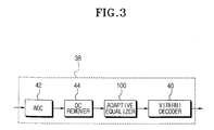
- the PRML block 38 has an ADC (analog-to-digital converter) 42 for converting the RF signal into a digital signal, a DC remover 44 for removing a DC component of the RF signal, an equalizer 100 for equalizing the digital RF signal from which the DC component has been removed, and a viterbi decoder 46 for recovering the data by decoding the signal equalized at the equalizer 100.
- the equalizer 100 equalizes the input RF signal to an output signal having the level required by the viterbi decoder 46.
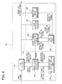
- FIG. 4 is a block diagram showing the adaptive equalizer 100 according to the present invention.
- the adaptive equalizer 100 according to the present invention has an FIR filter 110, an error detection part 120, a coefficient calculator 130, and a coefficient re-initialization part 140.
- the error detection part 120 comprises a sign detector 122, an absolute value calculator 124, a tap delay circuit 126, and a level error decision part 128.
- the FIR filter 110 equalizes the RF input signal to a form desired by a user and creates the equalized output signal.
- the characteristic of the equalization of the FIR filter 110 is decided by coefficients input from the coefficient calculator 130.
- the output signal output from the FIR filter 110 is provided to the viterbi decoder 46.
- the sign detector 122 detects the sign of the equalized output signal output from the FIR filter 110. In other words, the sign detector 122 outputs '1' when the sign of the equalized output signal is positive, and '-1' when the sign of the equalized output signal is negative.
- the sign of the output signal can be easily detected by using the most significant bit (MSB) of the input digital signal.
- the absolute value calculator 124 calculates an absolute value of the equalized output signal.
- the tap delay circuit 126 creates a series of sign values and a series of absolute values by delaying the sign values detected by the sign detector 122 and the absolute values of the signal calculated by the absolute value calculator 124.
- the sign values, the absolute values and the output signal of the FIR filter 110 are input to the level error decision part 128 from the tap delay circuit 126.
- the level error decision part 128 decides an error of the signal according to the method described later by using the sign values, the absolute values, and the output signal.
- the error is input to the coefficient calculator 130 from the level error decision part 128, and the coefficient calculator 130 calculates new coefficients of the FIR filter 110 by using the error.
- the calculated coefficients are provided to the FIR filter 110 and the coefficient re-initialization part 140.
- the coefficient re-initialization part 140 detects whether there is an abnormality in the gain of the FIR filter 110 by using the new coefficients calculated by the coefficient calculator 130. When it is detected that there is an abnormality, the coefficient re-initialization part 140 outputs a malfunction detection signal for initializing the coefficients of the FIR filter 110 to stable values.
- the adaptive equalizer 100 converts the input signal (RF signal of a DVD) having the feature shown in FIG. 5 into an RF signal of an optical model PR (a, b, b, a) shown in FIG. 6, required by the viterbi decoder 46. Then, the adaptive equalizer 100 according to the present invention converts the input RF signal into a digital signal with a low error ratio. Following is a detailed description of the operation of the adaptive equalizer 100.
- the input signal input into the FIR filter 110 after being read by the pick-up 34 in a DVD player has a form shown in FIG. 5. As shown in FIG. 5, the input signal has various signal levels according to the values, and the signal level is decided by a physical feature of the disk 32.
- FIG. 6 shows the characteristic of the signal required by the viterbi decoder 46.
- the signal level required by the viterbi decoder 46 is modeled mathematically upon the characteristics thereof, and FIG. 6 shows the reference levels according to the optical channel model PR (a, b, b, a).
- the channel model PR (a, b, b, a) can be expressed with the following mathematical expression.
- F (z) a + bz + bz 2 + az 3
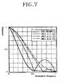
- FIG. 7 is a graph showing the comparison result of the difference of the characteristic between the input DVD RF signal and the RF signal in a PR (a, b, b, a) model in the frequency domain.
- the function of the adaptive equalizer 100 according to the present invention is to change the characteristic of the DVD RF signal as shown with a rigid line in FIG. 7 into the characteristic of the RF signal in PR (a, b, b, a) model as shown with a dotted line in FIG. 7.
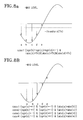
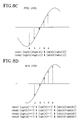
- the error detection part 120 detects the error between the level of the output signal of the FIR filter 110 and the level of the signal in PR (a, b, b, a) model by using the sign values and the absolute values of the input signal through an algorithm shown in FIGS. 8A to 8E.
- FIGS. 8A to 8E are views explaining error decision algorithms of the level error detection part 128.
- the level of the output signal respectively sampled in the output signal of the FIR filter 110 is calculated by using five sampled output signals.
- the object signal, two sampled output signals input before the object signal, and two sampled output signals input after the object signal are used.
- the level error detection part 128 judges that the object signal has a detection level corresponding to a maximum value among the reference levels, when the signs of the object signal and two signals respectively input just before and just after the object signal are identical to each other. At this time, the level error detection part 128 judges that the object signal has the detection level corresponding to the maximum value among the reference levels, when magnitudes of the object signal and two signals respectively input just before and after the object signal are all greater than a predetermined threshold value.
- the level error detection part 128 judges that the object signal has a detection level corresponding to one of a middle value and zero value among the reference values, when the signs of the object signal and two signals respectively input just before and just after the object signal are not identical to each other. At this time, whether the object signal has the middle value or zero value is judged by the comparison result of the magnitudes of the two adjacent signals.
- FIGS. 8A through 8E Following is a detailed description referring to FIGS. 8A through 8E.
- the object output signal is marked as 'c'
- two signals sampled before the object output signal 'c' are marked as 'd' and 'e'
- two signals sampled after the object output signal 'c' are marked as 'a' and 'b'.
- the level error detection part 128 in the error detection part 120 calculates the error of every data value by calculating the difference between the level of the output signal of the FIR filter 110 judged according to the above criteria and the actual level of the output signal of the FIR filter 110.
- the calculated error is used for calculating new coefficients at the coefficient calculator 130 by the LMS (least mean square) adaptive equalization algorithm expressed as the following mathematical expression.
- W k+1 W k + 2 ⁇ ⁇ X k
- the calculated coefficient values are provided to the FIR filter 110, and accordingly, the characteristic of the FIR filter 110 is controlled to output the output signal having a signal level optimized to the viterbi decoder 46 of PR (a, b, b, a) model.
- the coefficient re-initialization part 140 examines all of the coefficients calculated by the coefficient calculator 130, and detects whether the DC gain of the FIR filter 110 is too great or too small. When it is too great or too small, it is judged that the adaptive equalizer 100 cannot converge but diverges. Therefore, the coefficient re-initialization part 140 re-initializes the coefficient values so that the coefficients of the FIR filter 110 can be initialized to stable values, and thus the instability of the entire system is overcome.
- the DC gain of the FIR filter 110 can be easily calculated by adding all coefficient values input into the FIR filter 110.
- the re-initialization of the coefficients of the FIR filter 110 can be performed by first causing the coefficient re-initialization part 140 to transmit a malfunction detection signal to the coefficient calculator 130 and then causing the coefficient calculator 130 to set up the coefficient values output to the FIR filter 110 as the stable initial values.
- the adaptive equalizer 100 of the present invention uses not only the sign of the signal but also the value of the signal for calculating the error. Therefore, the reliability of the error calculation increases.
- the adaptive equalizer 100 cannot converge but diverges when the DC gain of the FIR filter 110 is too great or too small, considering the coefficients of the FIR filter 110 calculated by the coefficient calculator 130.
- the coefficient re-initialization part 140 initializes the coefficients of the FIR filter 110 as stable values, thus the stable operation of the adaptive equalizer 100 is guaranteed.
- the PRML block 38 for an optical disk applying the present invention has a low BER (bit error rate) when converting the input RF signal into the digital value, and can improve the stability of the optical disk system.
Landscapes
- Engineering & Computer Science (AREA)
- Signal Processing (AREA)
- Computer Networks & Wireless Communication (AREA)
- Cable Transmission Systems, Equalization Of Radio And Reduction Of Echo (AREA)
- Signal Processing For Digital Recording And Reproducing (AREA)
- Filters That Use Time-Delay Elements (AREA)
Abstract
Description
Claims (16)
- An adaptive equalizer comprising:an FIR filter for generating an equalized output signal by equalizing an RF input signal;a sign detector for detecting a sign of the output signal;an absolute value calculator for calculating an absolute value of the output signal;a level error detection part for detecting a detection level of the output signal using the sign and the absolute value, the detection level which is one of reference values required by a channel characteristic model of a decoder provided with the output signal, the level error detection part for calculating an error which is a difference between the detection level and an actual level of the output signal; anda coefficient calculator for calculating coefficients of the FIR filter based on the error, and for providing the calculated coefficients to the FIR filter.
- The adaptive equalizer as claimed in claim 1, wherein the level error detection part detects the detection level, by using an object signal which is an object for detecting the detection level, and a predetermined number of signals input before and after the object signal.
- The adaptive equalizer as claimed in claim 2, wherein the level error detection part judges that the object signal has the detection level corresponding to a maximum value among the reference levels when the signs of the object signal and two signals respectively input just before and just after the object signal are identical to each other.
- The adaptive equalizer as claimed in claim 3, wherein the level error detection part judges that the object signal has the detection level corresponding to the maximum value among the reference levels when magnitudes of the object signal and the two signals respectively input just before and just after the object signal are all greater than a predetermined threshold value.
- The adaptive equalizer as claimed in claim 2, wherein the level error detection part judges that the object signal has the detection level corresponding to one of a middle value and a zero value among the reference levels when the signs of the object signal and two signals respectively input just before and just after the object signal are not identical to each other.
- The adaptive equalizer as claimed in claim 5, wherein the level error detection part judges the detection level according to a comparison result of magnitudes of the two signals input just before and just after the object signal.
- The adaptive equalizer as claimed in claim 1, further comprising a coefficient re-initialization part for judging whether a gain of the FIR filter diverges or not, based on the coefficients, the coefficient re-initialization part for providing a malfunction detection signal to the coefficient calculator when judging that the FIR filter diverges.
- The adaptive equalizer as claimed in claim 7, wherein the coefficient calculator sets predetermined initial values as the coefficients and provides the coefficients to the FIR filter, when the malfunction detection signal is input thereto.
- An adaptive equalizing method comprising the steps of:calculating a sign and an absolute value of an equalized output signal which is an output of an FIR filter generated by equalizing an RF input signal;detecting a detection level of the output signal using the sign and the absolute value, the detection level which is one of reference values required by a channel characteristic model of a decoder provided with the output signal;calculating an error which is a difference between the detection level and an actual level of the output signal;calculating coefficients of the FIR filter based on the error; andproviding the calculated coefficients to the FIR filter.
- The adaptive equalizing method as claimed in claim 9, wherein, in the detecting step, the detection level is detected, by using an object signal which is an object for detecting the detection level, and a predetermined number of signals input before and after the object signal.
- The adaptive equalizing method as claimed in claim 10, wherein, in the detecting step, the object signal is judged to have the detection level corresponding to a maximum value among the reference levels when the signs of the object signal and two signals respectively input just before and just after the object signal are identical to each other.
- The adaptive equalizing method as claimed in claim 11, wherein, in the detecting step, the object signal is judged to have the detection level corresponding to the maximum value among the reference levels when magnitudes of the object signal and the two signals respectively input just before and just after the object signal are all greater than a predetermined threshold value.
- The adaptive equalizing method as claimed in claim 10, wherein, in the detecting step, the object signal is judged to have the detection level corresponding to one of a middle value and zero value among the reference levels when the signs of the object signal and two signals respectively input just before and just after the object signal are not identical to each other.
- The adaptive equalizing method as claimed in claim 13, wherein, in the detecting step, the detection level is detected according to a comparison result of the magnitudes of the two signals input just before and just after the object signal.
- The adaptive equalizing method as claimed in claim 9, further comprising the steps of:judging whether a gain of the FIR filter diverges or not, based on the coefficients; andgenerating a malfunction detection signal when it is judged that the FIR filter diverges.
- The adaptive equalizing method as claimed in claim 15, further comprising a step of initializing the coefficients to predetermined initial values when the malfunction detection signal is generated.
Applications Claiming Priority (2)
| Application Number | Priority Date | Filing Date | Title |
|---|---|---|---|
| KR10-2001-0078275A KR100416265B1 (en) | 2001-12-11 | 2001-12-11 | Adaptive Equalizer controlling the operation thereof using a sign and an absolute value of an output signal thereof |
| KR2001078275 | 2001-12-11 |
Publications (2)
| Publication Number | Publication Date |
|---|---|
| EP1320097A2 true EP1320097A2 (en) | 2003-06-18 |
| EP1320097A3 EP1320097A3 (en) | 2005-11-30 |
Family
ID=19716899
Family Applications (1)
| Application Number | Title | Priority Date | Filing Date |
|---|---|---|---|
| EP02026411A Withdrawn EP1320097A3 (en) | 2001-12-11 | 2002-11-26 | Adaptive equalizer |
Country Status (5)
| Country | Link |
|---|---|
| US (1) | US7184476B2 (en) |
| EP (1) | EP1320097A3 (en) |
| JP (1) | JP2003217233A (en) |
| KR (1) | KR100416265B1 (en) |
| CN (1) | CN1224045C (en) |
Cited By (2)
| Publication number | Priority date | Publication date | Assignee | Title |
|---|---|---|---|---|
| EP1575176A1 (en) * | 2004-03-09 | 2005-09-14 | Deutsche Thomson-Brandt Gmbh | Arrangement for adaptive bit recovery |
| GB2416969A (en) * | 2004-07-29 | 2006-02-08 | Hewlett Packard Development Co | Equalisers |
Families Citing this family (12)
| Publication number | Priority date | Publication date | Assignee | Title |
|---|---|---|---|---|
| US7194026B2 (en) * | 2001-04-26 | 2007-03-20 | Thomson Licensing | Blind equalization method for a high definition television signal |
| US7286311B1 (en) * | 2001-05-07 | 2007-10-23 | Marvell International Ltd. | Thermal asperity compensation in perpendicular recording |
| KR20050026320A (en) * | 2003-09-09 | 2005-03-15 | 삼성전자주식회사 | Device and method for data reproduction |
| US7545859B2 (en) * | 2004-01-14 | 2009-06-09 | L-3 Communications Integrated Systems L.P. | Adaptive channel equalization technique and method for wideband passive digital receivers |
| TWI336168B (en) * | 2004-04-13 | 2011-01-11 | Realtek Semiconductor Corp | Method and apparatus for tuning a digital filter |
| CN100483532C (en) * | 2004-09-13 | 2009-04-29 | 瑞昱半导体股份有限公司 | Method and apparatus for adjusting digital filter |
| KR100688510B1 (en) | 2004-12-20 | 2007-03-02 | 삼성전자주식회사 | Coefficient updating circuit, adaptive equalizer including the same, and coefficient updating method of adaptive equalizer |
| US8218615B2 (en) | 2005-03-29 | 2012-07-10 | Qualcomm Incorporated | Method and apparatus for block-wise decision-feedback equalization for wireless communication |
| US8615035B2 (en) | 2005-03-29 | 2013-12-24 | Qualcomm Incorporated | Method and apparatus for block-wise decision-feedback equalization for wireless communication |
| KR20080040892A (en) * | 2006-11-06 | 2008-05-09 | 삼성전자주식회사 | Adaptive equalizer and adaptive equalization method |
| JP4940347B1 (en) * | 2010-12-17 | 2012-05-30 | 株式会社東芝 | Correction filter processing apparatus and method |
| CN113992485B (en) * | 2021-10-27 | 2023-05-30 | 西安微电子技术研究所 | Decision feedback equalization circuit and high-speed signal channel transmission system |
Family Cites Families (14)
| Publication number | Priority date | Publication date | Assignee | Title |
|---|---|---|---|---|
| US5297165A (en) * | 1990-07-06 | 1994-03-22 | Nippon Telegraph And Telephone Corporation | Equalizer for radio receive signal |
| AU655384B2 (en) * | 1991-07-26 | 1994-12-15 | General Instrument Corporation | Carrier phase recovery for an adaptive equalizer |
| JP3250678B2 (en) | 1992-08-25 | 2002-01-28 | ソニー株式会社 | Coefficient processing method, coefficient processing circuit, and video tape recorder |
| JP3366803B2 (en) * | 1996-05-28 | 2003-01-14 | パイオニア株式会社 | Adaptive equalizer |
| JP3099745B2 (en) * | 1996-08-13 | 2000-10-16 | 日本電気株式会社 | Automatic equalizer |
| JP3428329B2 (en) * | 1996-10-31 | 2003-07-22 | 日本ビクター株式会社 | Waveform equalization circuit |
| US5999349A (en) * | 1996-12-30 | 1999-12-07 | Daewoo Electronics Co., Ltd. | Waveform equalization apparatus |
| KR19990066518A (en) * | 1998-01-30 | 1999-08-16 | 전주범 | Mode conversion control device of adaptive equalizer |
| JP3781911B2 (en) * | 1999-01-07 | 2006-06-07 | 株式会社日立製作所 | Information reproducing method and apparatus |
| KR100580166B1 (en) | 1999-11-04 | 2006-05-15 | 삼성전자주식회사 | Apparatus and method for improving playback performance by adjusting filter coefficients of equalizer |
| JP2001155429A (en) * | 1999-11-25 | 2001-06-08 | Hitachi Ltd | Automatic equalizing circuit and reproducing apparatus using the same |
| KR100708070B1 (en) | 2000-01-10 | 2007-04-17 | 삼성전자주식회사 | Data reproducing apparatus and method for improving detection performance by adjusting crystal level used in data detector |
| US6907092B1 (en) * | 2000-07-14 | 2005-06-14 | Comsys Communication & Signal Processing Ltd. | Method of channel order selection and channel estimation in a wireless communication system |
| US6732129B1 (en) * | 2000-10-04 | 2004-05-04 | Spanta J. Ashjaee | Adaptive filtering and learning system having increased convergence speed and stability |
-
2001
- 2001-12-11 KR KR10-2001-0078275A patent/KR100416265B1/en not_active Expired - Fee Related
-
2002
- 2002-11-26 EP EP02026411A patent/EP1320097A3/en not_active Withdrawn
- 2002-12-10 CN CNB021540772A patent/CN1224045C/en not_active Expired - Fee Related
- 2002-12-11 US US10/316,019 patent/US7184476B2/en not_active Expired - Fee Related
- 2002-12-11 JP JP2002359118A patent/JP2003217233A/en active Pending
Cited By (4)
| Publication number | Priority date | Publication date | Assignee | Title |
|---|---|---|---|---|
| EP1575176A1 (en) * | 2004-03-09 | 2005-09-14 | Deutsche Thomson-Brandt Gmbh | Arrangement for adaptive bit recovery |
| US8077817B2 (en) | 2004-03-09 | 2011-12-13 | Thomson Licensing | Arrangement for adaptive bit recovery |
| GB2416969A (en) * | 2004-07-29 | 2006-02-08 | Hewlett Packard Development Co | Equalisers |
| US7720139B2 (en) | 2004-07-29 | 2010-05-18 | Hewlett-Packard Development Company, L.P. | Equaliser circuit |
Also Published As
| Publication number | Publication date |
|---|---|
| KR20030047572A (en) | 2003-06-18 |
| US7184476B2 (en) | 2007-02-27 |
| CN1427408A (en) | 2003-07-02 |
| KR100416265B1 (en) | 2004-01-24 |
| JP2003217233A (en) | 2003-07-31 |
| US20030108097A1 (en) | 2003-06-12 |
| EP1320097A3 (en) | 2005-11-30 |
| CN1224045C (en) | 2005-10-19 |
Similar Documents
| Publication | Publication Date | Title |
|---|---|---|
| US6747936B1 (en) | Data reproduction apparatus and method with improved performance by adjusting filter coefficients of equalizer | |
| US6934233B2 (en) | Waveform equalizer for a reproduction signal obtained by reproducing marks and non-marks recorded on a recording medium | |
| US6977970B2 (en) | Data reproducing apparatus and method for improving detection performance by adjusting decision levels used in data detector | |
| US7184476B2 (en) | Adaptive equalizer for controlling operation thereof by using sign and absolute value of output signal thereof | |
| WO2000046802A1 (en) | Adaptive equalizing circuit | |
| US5999349A (en) | Waveform equalization apparatus | |
| JP4216259B2 (en) | High speed hybrid analog / digital PRML data detection and clock recovery apparatus and method for data storage | |
| JP2004080210A (en) | Digital filter | |
| JP3428329B2 (en) | Waveform equalization circuit | |
| JP2000228064A (en) | Decoding device of optical disk | |
| US7151642B2 (en) | Information playback method and apparatus | |
| WO2005024822A1 (en) | Reproduced signal processor and reproduced signal processing method | |
| US5805478A (en) | Data detection method and apparatus in data storage device | |
| JP2005093053A (en) | Data reproducing apparatus and method | |
| US7567491B1 (en) | Slicer bias loop | |
| CN109643559B (en) | Signal quality evaluation device, signal quality evaluation value generation method, and reproduction device | |
| JP3588344B2 (en) | Signal reproducing apparatus and method | |
| JP3250678B2 (en) | Coefficient processing method, coefficient processing circuit, and video tape recorder | |
| JPH10199144A (en) | Maximum likelihood decoder | |
| JP3083202B2 (en) | Information playback device | |
| KR100408281B1 (en) | Signal reproducing apparatus and method for compensating for channel distortion | |
| JPH10199161A (en) | Data reproduction system applied to data recording / reproduction device | |
| JP3994987B2 (en) | Playback device | |
| US20050058191A1 (en) | Method and apparatus for detecting signal quality and recording medium storing program therefor | |
| JP2005141857A (en) | Digital signal decoding device |
Legal Events
| Date | Code | Title | Description |
|---|---|---|---|
| PUAI | Public reference made under article 153(3) epc to a published international application that has entered the european phase |
Free format text: ORIGINAL CODE: 0009012 |
|
| 17P | Request for examination filed |
Effective date: 20021126 |
|
| AK | Designated contracting states |
Designated state(s): AT BE BG CH CY CZ DE DK EE ES FI FR GB GR IE IT LI LU MC NL PT SE SK TR |
|
| AX | Request for extension of the european patent |
Extension state: AL LT LV MK RO SI |
|
| PUAL | Search report despatched |
Free format text: ORIGINAL CODE: 0009013 |
|
| AK | Designated contracting states |
Kind code of ref document: A3 Designated state(s): AT BE BG CH CY CZ DE DK EE ES FI FR GB GR IE IT LI LU MC NL PT SE SK TR |
|
| AX | Request for extension of the european patent |
Extension state: AL LT LV MK RO SI |
|
| AKX | Designation fees paid |
Designated state(s): CH DE FR GB LI NL |
|
| STAA | Information on the status of an ep patent application or granted ep patent |
Free format text: STATUS: THE APPLICATION HAS BEEN WITHDRAWN |
|
| 18W | Application withdrawn |
Effective date: 20090525 |